Operating Instructions
Page 2
... cabinet. Owner's Record The model and serial numbers are designed to rain or moisture. DAV-HDX589W Serial No Date of Manufacture Marking is located on the apparatus. Reorient or relocate the... is located on the rear exterior of the unit. Should you call upon your Sony dealer regarding this model manufactured for a Class B digital device, pursuant to them whenever...curtains, etc. Do not install the appliance in a confined space, such as it is connected to radio communications. Indoor use of uninsulated "dangerous voltage" within the product's enclosure that ...
... cabinet. Owner's Record The model and serial numbers are designed to rain or moisture. DAV-HDX589W Serial No Date of Manufacture Marking is located on the apparatus. Reorient or relocate the... is located on the rear exterior of the unit. Should you call upon your Sony dealer regarding this model manufactured for a Class B digital device, pursuant to them whenever...curtains, etc. Do not install the appliance in a confined space, such as it is connected to radio communications. Indoor use of uninsulated "dangerous voltage" within the product's enclosure that ...
Operating Instructions
Page 3
...OET65. This equipment should be installed and operated with RSS-Gen of this equipment. Install in conjunction with the apparatus. Servicing is connected. - CAUTION You are provided for the customers in Supplement C to avoid injury from being walked on a circuit different from that... prong. Consult the dealer or an experienced radio/TV technician for energy efficiency. registered mark. As an ENERGY STAR® partner, Sony Corporation has determined that produce heat. 9) Do not defeat the safety purpose of the IC radio frequency (RF) Exposure rules. This...
...OET65. This equipment should be installed and operated with RSS-Gen of this equipment. Install in conjunction with the apparatus. Servicing is connected. - CAUTION You are provided for the customers in Supplement C to avoid injury from being walked on a circuit different from that... prong. Consult the dealer or an experienced radio/TV technician for energy efficiency. registered mark. As an ENERGY STAR® partner, Sony Corporation has determined that produce heat. 9) Do not defeat the safety purpose of the IC radio frequency (RF) Exposure rules. This...
Operating Instructions
Page 6
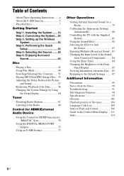
... About These Operating Instructions ....... 4 About the S-AIR function 5 Playable Discs 7 Getting Started Step 1: Installing the System .......13 Step 2: Connecting the System ...24 Step 3: Setting up the Wireless System 34 Step 4: Performing the Quick Setup 35 Step 5: Selecting the Source .......39 Step 6: Enjoying Surround Sound 40 ...Radio Stations 67 Listening to the Radio 68 Control for HDMI/External Audio Device Using the Control for HDMI Function for "BRAVIA" Sync 70 Using the DIGITAL MEDIA PORT Adapter 72 Using an S-AIR Product 73 Other Operations Getting Optimal Surround Sound...
... About These Operating Instructions ....... 4 About the S-AIR function 5 Playable Discs 7 Getting Started Step 1: Installing the System .......13 Step 2: Connecting the System ...24 Step 3: Setting up the Wireless System 34 Step 4: Performing the Quick Setup 35 Step 5: Selecting the Source .......39 Step 6: Enjoying Surround Sound 40 ...Radio Stations 67 Listening to the Radio 68 Control for HDMI/External Audio Device Using the Control for HDMI Function for "BRAVIA" Sync 70 Using the DIGITAL MEDIA PORT Adapter 72 Using an S-AIR Product 73 Other Operations Getting Optimal Surround Sound...
Operating Instructions
Page 15
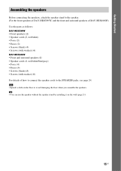
... on the wall (page 21). 15US Getting Started Assembling the speakers Before connecting the speakers, attach the speaker stand to the speaker. (For the front speakers of DAV-HDX589W, and the front and surround speakers of DAV-HDX686W) Use the parts as follows: DAV-HDX589W • Front speakers (2) • Speaker cords (2, red/white) • Posts (2) •...
... on the wall (page 21). 15US Getting Started Assembling the speakers Before connecting the speakers, attach the speaker stand to the speaker. (For the front speakers of DAV-HDX589W, and the front and surround speakers of DAV-HDX686W) Use the parts as follows: DAV-HDX589W • Front speakers (2) • Speaker cords (2, red/white) • Posts (2) •...
Operating Instructions
Page 17
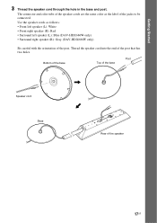
...: • Front left speaker (L): White • Front right speaker (R): Red • Surround left speaker (L): Blue (DAV-HDX686W only) • Surround right speaker (R): Gray (DAV-HDX686W only) Be careful with the orientation of the jacks to be connected. Bottom of the base Top of the base Post Speaker cord , , Base Rear of the post...
...: • Front left speaker (L): White • Front right speaker (R): Red • Surround left speaker (L): Blue (DAV-HDX686W only) • Surround right speaker (R): Gray (DAV-HDX686W only) Be careful with the orientation of the jacks to be connected. Bottom of the base Top of the base Post Speaker cord , , Base Rear of the post...
Operating Instructions
Page 18
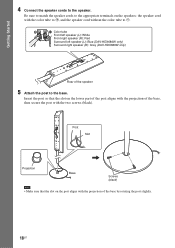
... speaker 5 Attach the post to the speaker. Color tube Front left speaker (L): White Front right speaker (R): Red Surround left speaker (L): Blue (DAV-HDX686W only) Surround right speaker (R): Gray (DAV-HDX686W only) Rear of the base, then secure the post with the two screws (black). Getting Started 4 Connect the speaker cords to the base.
... speaker 5 Attach the post to the speaker. Color tube Front left speaker (L): White Front right speaker (R): Red Surround left speaker (L): Blue (DAV-HDX686W only) Surround right speaker (R): Gray (DAV-HDX686W only) Rear of the base, then secure the post with the two screws (black). Getting Started 4 Connect the speaker cords to the base.
Operating Instructions
Page 21
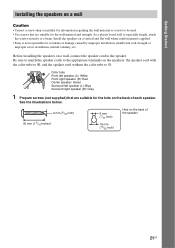
... the illustrations below. 4 mm (5/32 inch) 30 mm (1 3/16 inches) 5 mm (7/32 inch) 10 mm (13/32 inch) Hole on a wall, connect the speaker cord to the speaker. Getting Started Installing the speakers on a wall Caution • Contact a screw shop or installer for information regarding the wall...each speaker. Be sure to match the speaker cords to the appropriate terminals on a vertical and flat wall where reinforcement is applied. • Sony is especially fragile, attach the screws securely to #. Install the speakers on the speakers: the speaker cord with the color tube to 3, and...
... the illustrations below. 4 mm (5/32 inch) 30 mm (1 3/16 inches) 5 mm (7/32 inch) 10 mm (13/32 inch) Hole on a wall, connect the speaker cord to the speaker. Getting Started Installing the speakers on a wall Caution • Contact a screw shop or installer for information regarding the wall...each speaker. Be sure to match the speaker cords to the appropriate terminals on a vertical and flat wall where reinforcement is applied. • Sony is especially fragile, attach the screws securely to #. Install the speakers on the speakers: the speaker cord with the color tube to 3, and...

Operating Instructions
Page 24
... appropriate terminals on the speakers: the speaker cord with a volume control, turn down the volume of the unit. To connect speaker cords to the unit When connecting to #. Getting Started Step 2: Connecting the System For connecting the system, read the information on the type of the surround amplifier EZW-RT10 S-AIR ID A B C SPEAKER L PAIRING R SURROUND SESSUULRRBERRACOOCKUUTNNODDR...
... appropriate terminals on the speakers: the speaker cord with a volume control, turn down the volume of the unit. To connect speaker cords to the unit When connecting to #. Getting Started Step 2: Connecting the System For connecting the system, read the information on the type of the surround amplifier EZW-RT10 S-AIR ID A B C SPEAKER L PAIRING R SURROUND SESSUULRRBERRACOOCKUUTNNODDR...

Operating Instructions
Page 25
Getting Started To connect speaker cords to the speaker Connector (-) Color tube (+) Rear of the speaker 25US
Getting Started To connect speaker cords to the speaker Connector (-) Color tube (+) Rear of the speaker 25US

Operating Instructions
Page 26
...A Video cord (supplied) B HDMI cable (not supplied) To the HDMI IN jack of the TV. Method 1: Video cord (A) connection This is the basic connection. To view images from the DIGITAL MEDIA PORT adapter are not output via the HDMI OUT jack. * HDMI (High-Definition Multimedia Interface)...component video cable and video cord. Method 2: HDMI* cable (B) and video cord (A) connection If your TV, select the connection method. When connecting with the component video cable, you need to connect to progressive format (page 37). Video signals from the DIGITAL MEDIA PORT adapter, you ...
...A Video cord (supplied) B HDMI cable (not supplied) To the HDMI IN jack of the TV. Method 1: Video cord (A) connection This is the basic connection. To view images from the DIGITAL MEDIA PORT adapter are not output via the HDMI OUT jack. * HDMI (High-Definition Multimedia Interface)...component video cable and video cord. Method 2: HDMI* cable (B) and video cord (A) connection If your TV, select the connection method. When connecting with the component video cable, you need to connect to progressive format (page 37). Video signals from the DIGITAL MEDIA PORT adapter, you ...

Operating Instructions
Page 27
... Note • The system can accept both digital and analog signals. Digital signals have priority over analog signals. (COAXIAL has priority over OPTICAL.) If the digital signal ceases, the analog signal will be processed after 2 seconds. Method 1: Audio cord (D) connection This is the basic connection and sends an analog ... AUDIO IN L D Audio cord (not supplied) F Digital coaxial cord (not supplied) To the digital optical out jack of the TV. 27US Getting Started Connecting the TV (Audio connection) This connection sends an audio signal to TV sound via the system, perform this...
... Note • The system can accept both digital and analog signals. Digital signals have priority over analog signals. (COAXIAL has priority over OPTICAL.) If the digital signal ceases, the analog signal will be processed after 2 seconds. Method 1: Audio cord (D) connection This is the basic connection and sends an analog ... AUDIO IN L D Audio cord (not supplied) F Digital coaxial cord (not supplied) To the digital optical out jack of the TV. 27US Getting Started Connecting the TV (Audio connection) This connection sends an audio signal to TV sound via the system, perform this...

Operating Instructions
Page 28
...of the TV. 28US When disconnecting, pull out while pressing . Tip • You can enjoy connected components via the system's speakers. Portable audio source (not supplied): G DIGITAL MEDIA PORT adapter: H (TDM-iP20 is supplied with U.S. Getting Started Connecting the other DIGITAL MEDIA PORT adapters.) G Stereo mini-plug cord (not supplied) SPEAKER CENTER SUBWOOFER... AM FM COAXIAL 75 COMPONENT VIDEO OUT VOIDUETO PR/CR PB/CB Y TV/VIDEO R AUDIO IN L H DIGITAL MEDIA PORT adapter (page 72) Note • Connect the DIGITAL MEDIA PORT adapter so that the V marks are aligned.
...of the TV. 28US When disconnecting, pull out while pressing . Tip • You can enjoy connected components via the system's speakers. Portable audio source (not supplied): G DIGITAL MEDIA PORT adapter: H (TDM-iP20 is supplied with U.S. Getting Started Connecting the other DIGITAL MEDIA PORT adapters.) G Stereo mini-plug cord (not supplied) SPEAKER CENTER SUBWOOFER... AM FM COAXIAL 75 COMPONENT VIDEO OUT VOIDUETO PR/CR PB/CB Y TV/VIDEO R AUDIO IN L H DIGITAL MEDIA PORT adapter (page 72) Note • Connect the DIGITAL MEDIA PORT adapter so that the V marks are aligned.
Operating Instructions
Page 29
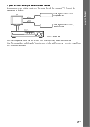
Connect the components as follows. Getting Started If your TV has multiple audio/video inputs You can enjoy sound with the speakers of the TV. TV VCR, digital satellite receiver, PlayStation, etc. For details, refer to receive sound from more than one component. 29US If the TV does not have multiple audio/video inputs, a switcher will be necessary to the operating instructions of the system through the connected TV. System VCR, digital satellite receiver, PlayStation, etc. :Signal flow Select the component on the TV.
Connect the components as follows. Getting Started If your TV has multiple audio/video inputs You can enjoy sound with the speakers of the TV. TV VCR, digital satellite receiver, PlayStation, etc. For details, refer to receive sound from more than one component. 29US If the TV does not have multiple audio/video inputs, a switcher will be necessary to the operating instructions of the system through the connected TV. System VCR, digital satellite receiver, PlayStation, etc. :Signal flow Select the component on the TV.

Operating Instructions
Page 30
...the AM loop antenna (aerial) Getting Started To connect the antenna (aerial) ANTENNA AM AM FM COAXIAL 75 or AM loop antenna (aerial) (supplied) FM wire antenna (aerial) (supplied) Note • Keep the AM loop antenna (aerial) and cord away from the system or other AV components, as noise may result... antenna (aerial) for best AM broadcast sound. • If you have poor FM reception, use a 75-ohm coaxial cable (not supplied) to connect the unit to fully extend the FM wire antenna (aerial). • After connecting the FM wire antenna (aerial), keep it as horizontal as shown below.
...the AM loop antenna (aerial) Getting Started To connect the antenna (aerial) ANTENNA AM AM FM COAXIAL 75 or AM loop antenna (aerial) (supplied) FM wire antenna (aerial) (supplied) Note • Keep the AM loop antenna (aerial) and cord away from the system or other AV components, as noise may result... antenna (aerial) for best AM broadcast sound. • If you have poor FM reception, use a 75-ohm coaxial cable (not supplied) to connect the unit to fully extend the FM wire antenna (aerial). • After connecting the FM wire antenna (aerial), keep it as horizontal as shown below.

Operating Instructions
Page 31
... wireless transceiver You can transmit sound from the unit, you insert the wireless transceiver, make sure that the AC power cord (mains lead) is not connected to a wall outlet (mains). • Do not touch the terminals of the wireless transceiver. • Insert the wireless transceiver so that the V marks are aligned...
... wireless transceiver You can transmit sound from the unit, you insert the wireless transceiver, make sure that the AC power cord (mains lead) is not connected to a wall outlet (mains). • Do not touch the terminals of the wireless transceiver. • Insert the wireless transceiver so that the V marks are aligned...

Operating Instructions
Page 32
...shape of the unit and the surround amplifier to a wall outlet (mains), connect the front, center speakers and subwoofer to the unit and surround speakers to on/off . 32US The system menu turns off 1 Press [/1 on . 2 Press SYSTEM MENU. 3 Press X/x repeatedly until "DEMO" appears in the front panel... display. About the demonstration After connecting the AC power cord (mains lead), the demonstration appears in the ...
...shape of the unit and the surround amplifier to a wall outlet (mains), connect the front, center speakers and subwoofer to the unit and surround speakers to on/off . 32US The system menu turns off 1 Press [/1 on . 2 Press SYSTEM MENU. 3 Press X/x repeatedly until "DEMO" appears in the front panel... display. About the demonstration After connecting the AC power cord (mains lead), the demonstration appears in the ...

Operating Instructions
Page 34
...SELECTOR R SURROUND SURROUND BACK PHONES jack SURROUND SELECTOR switch The unit transmits sound to the surround amplifier that the wireless transceivers are connected to the PHONES jack on the surround amplifier. If it doesn't, check the transmission status as follows. To check the transmission ...of the surround amplifier, see "Using an S-AIR Product" (page 73). The system turns on the unit. To enjoy sound by connecting the headphones to the surround amplifier, or radio reception is connected to A. 4 Press POWER on the surround amplifier. Flashes green. Before setting, make...
...SELECTOR R SURROUND SURROUND BACK PHONES jack SURROUND SELECTOR switch The unit transmits sound to the surround amplifier that the wireless transceivers are connected to the PHONES jack on the surround amplifier. If it doesn't, check the transmission status as follows. To check the transmission ...of the surround amplifier, see "Using an S-AIR Product" (page 73). The system turns on the unit. To enjoy sound by connecting the headphones to the surround amplifier, or radio reception is connected to A. 4 Press POWER on the surround amplifier. Flashes green. Before setting, make...
Operating Instructions
Page 35
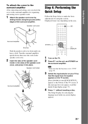
...• Make sure that the function is set to "DVD" (page 39). 3 Switch the input selector on your TV so that the signal from the system appears on the area. Speaker cord holder Surround amplifier m C/X/x/c, DISPLAY 1 Turn on the TV. 2 Press [/1 on the unit, and POWER on -screen...appear, recall the Quick Setup display (page 37). 4 Press without inserting a disc. Getting Started To attach the cover to the surround amplifier After connecting and setting, you hear a click. Speaker cord cover Step 4: Performing the Quick Setup Follow the Steps below to make the basic adjustments for ...
...• Make sure that the function is set to "DVD" (page 39). 3 Switch the input selector on your TV so that the signal from the system appears on the area. Speaker cord holder Surround amplifier m C/X/x/c, DISPLAY 1 Turn on the TV. 2 Press [/1 on the unit, and POWER on -screen...appear, recall the Quick Setup display (page 37). 4 Press without inserting a disc. Getting Started To attach the cover to the surround amplifier After connecting and setting, you hear a click. Speaker cord cover Step 4: Performing the Quick Setup Follow the Steps below to make the basic adjustments for ...

Operating Instructions
Page 36
...Getting Optimal Surround Sound for HDMI function is set to the A.CAL MIC jack on . • [OFF]: The Control for a Room" (page 79). 9 Connect the calibration mic (supplied) to off. Calibration mic 7 Press X/x to select the setting, then press . • [ON]: The Control for HDMI function (page ... 61) The Setup Display for the Control for selecting the aspect ratio of each speaker should face the calibration mic, and there should be connected appears. HDMI SETUP HDMI RESOLUTION: CONTROL FOR HDMI: VOLUME LIMIT: YCBCR/RGB(HDMI): AUDIO(HDMI): JPEG RESOLUTION: AUTO(1920x1080p) ON ON ...
...Getting Optimal Surround Sound for HDMI function is set to the A.CAL MIC jack on . • [OFF]: The Control for a Room" (page 79). 9 Connect the calibration mic (supplied) to off. Calibration mic 7 Press X/x to select the setting, then press . • [ON]: The Control for HDMI function (page ... 61) The Setup Display for the Control for selecting the aspect ratio of each speaker should face the calibration mic, and there should be connected appears. HDMI SETUP HDMI RESOLUTION: CONTROL FOR HDMI: VOLUME LIMIT: YCBCR/RGB(HDMI): AUDIO(HDMI): JPEG RESOLUTION: AUTO(1920x1080p) ON ON ...

Operating Instructions
Page 37
...surround amplifier in an improper location, such as another room, proper measurement will not be obtained. • The environment of the system. For details, refer also to match your TV Depending on the connection of the TV (page 26), select the type of video output of the room in which the... Give consideration to select [SETUP], then press . repeatedly until "DVD" appears in the appropriate location. The Quick Setup display appears. The options for the connected TV. • [1920 × 1080i]: The system outputs 1920 × 1080i* video signals. • [1280 × 720p]: The...
...surround amplifier in an improper location, such as another room, proper measurement will not be obtained. • The environment of the system. For details, refer also to match your TV Depending on the connection of the TV (page 26), select the type of video output of the room in which the... Give consideration to select [SETUP], then press . repeatedly until "DVD" appears in the appropriate location. The Quick Setup display appears. The options for the connected TV. • [1920 × 1080i]: The system outputs 1920 × 1080i* video signals. • [1280 × 720p]: The...


