
Operating Instructions
Page 4
...SYNC) Selecting a Playback Area for a Super Audio CD 53 About MP3 Audio Tracks and JPEG Image Files 54 Playing DATA CDs or DATA DVDs with MP3 Audio Tracks and JPEG Image Files 56 Playing Audio Tracks and Images as a Slide Show with Sound 58 Playing VIDEO CDs with ... THEATRE SYNC Function 68 Using the Sound Effect 69 Using the Sleep Timer 70 Step 1: Assembling the Speakers and Installing the Surround Amplifier 10 Step 2: Connecting the System and TV 16 Step 3: Positioning the System ...20 Step 4: Performing the Quick Setup 21 Getting Started - Table of Contents Welcome 3 About This...
...SYNC) Selecting a Playback Area for a Super Audio CD 53 About MP3 Audio Tracks and JPEG Image Files 54 Playing DATA CDs or DATA DVDs with MP3 Audio Tracks and JPEG Image Files 56 Playing Audio Tracks and Images as a Slide Show with Sound 58 Playing VIDEO CDs with ... THEATRE SYNC Function 68 Using the Sound Effect 69 Using the Sleep Timer 70 Step 1: Assembling the Speakers and Installing the Surround Amplifier 10 Step 2: Connecting the System and TV 16 Step 3: Positioning the System ...20 Step 4: Performing the Quick Setup 21 Getting Started - Table of Contents Welcome 3 About This...

Operating Instructions
Page 5
... Settings for the Display 80 [SCREEN SETUP] Custom Settings 82 [CUSTOM SETUP] Settings for the Speakers 83 [SPEAKER SETUP] Returning to the Default Settings.......... 85 Additional Information Precautions 86 Notes about the Discs 87 ...Troubleshooting 87 Self-diagnosis Function 91 (When letters/numbers appear in the display) Specifications 92 Glossary 94 Language Code List 98 Index to Parts and Controls 99 Guide to the Control Menu Display.... 102 DVD...
... Settings for the Display 80 [SCREEN SETUP] Custom Settings 82 [CUSTOM SETUP] Settings for the Speakers 83 [SPEAKER SETUP] Returning to the Default Settings.......... 85 Additional Information Precautions 86 Notes about the Discs 87 ...Troubleshooting 87 Self-diagnosis Function 91 (When letters/numbers appear in the display) Specifications 92 Glossary 94 Language Code List 98 Index to Parts and Controls 99 Guide to the Control Menu Display.... 102 DVD...

Operating Instructions
Page 10
... (page 25). 1 Secure the post to avoid damaging the floor. Screws with the screws. Tip • You can use . Step 1: Assembling the Speakers and Installing the Surround Amplifier Before connecting the speakers, attach the speaker stand to the SPEAKER jacks, see page 17. The IR receiver cord should be used for tabletop use the... speaker without the speaker stand by installing it on the floor to the base. Post (long) or Post (short) Base 2 Secure the base with washer (long) (3) (supplied) 10US Bottom ...
... (page 25). 1 Secure the post to avoid damaging the floor. Screws with the screws. Tip • You can use . Step 1: Assembling the Speakers and Installing the Surround Amplifier Before connecting the speakers, attach the speaker stand to the SPEAKER jacks, see page 17. The IR receiver cord should be used for tabletop use the... speaker without the speaker stand by installing it on the floor to the base. Post (long) or Post (short) Base 2 Secure the base with washer (long) (3) (supplied) 10US Bottom ...

Operating Instructions
Page 11
Screws with the screws. IR receiver cord , Speaker cord 5 Secure the pedestal to a straight length of the base Untwist and straighten out the speaker cord. Bottom of about 100 mm (4 inch) and twist together. Getting Started - BASIC - 3 Pull the speaker cord out to the post with washer (long) (3) (supplied) continued 11US Stand the speaker up, and untwist and straighten out the speaker cord. About 100 mm (4 inch) 4 Draw the IR receiver cord first, and then the speaker cord through the hole on the base. Fold back about 700 mm (28 inch).
Screws with the screws. IR receiver cord , Speaker cord 5 Secure the pedestal to a straight length of the base Untwist and straighten out the speaker cord. Bottom of about 100 mm (4 inch) and twist together. Getting Started - BASIC - 3 Pull the speaker cord out to the post with washer (long) (3) (supplied) continued 11US Stand the speaker up, and untwist and straighten out the speaker cord. About 100 mm (4 inch) 4 Draw the IR receiver cord first, and then the speaker cord through the hole on the base. Fold back about 700 mm (28 inch).

Operating Instructions
Page 12
Getting Started - Then run the cord around the pin. 7 Connect the speaker cords to the speaker and run the cords through the slots (A, B, C, and D) all the way. BASIC - 6 Connect the IR receiver cord to the speaker. A B C D 12US
Getting Started - Then run the cord around the pin. 7 Connect the speaker cords to the speaker and run the cords through the slots (A, B, C, and D) all the way. BASIC - 6 Connect the IR receiver cord to the speaker. A B C D 12US

Operating Instructions
Page 13
.... continued 13US The illustrations below show how to attach the surround speaker (L) to the speaker base. Note • Do not catch the speaker cord (and the IR receiver cord) between the speaker and the pedestal. • Do not drop the speaker when mounting. 9 Secure the speaker with the screws in order 1 to 2. 1 2 Screws with washer (short...
.... continued 13US The illustrations below show how to attach the surround speaker (L) to the speaker base. Note • Do not catch the speaker cord (and the IR receiver cord) between the speaker and the pedestal. • Do not drop the speaker when mounting. 9 Secure the speaker with the screws in order 1 to 2. 1 2 Screws with washer (short...

Operating Instructions
Page 14
Getting Started - Run cords through the slot. 14US Screws (4) (supplied) Rear of surround speaker 3 Secure the surround amplifier (speaker base) with the screws to the surround speaker with the guide pins. BASIC - 1 Attach the spacers. Spacers (4) (supplied) Guide pins (2) (supplied) Push open the cover (surround amplifier only). 2 Attach the surround amplifier (speaker base) to the circle marked holes.
Getting Started - Run cords through the slot. 14US Screws (4) (supplied) Rear of surround speaker 3 Secure the surround amplifier (speaker base) with the screws to the surround speaker with the guide pins. BASIC - 1 Attach the spacers. Spacers (4) (supplied) Guide pins (2) (supplied) Push open the cover (surround amplifier only). 2 Attach the surround amplifier (speaker base) to the circle marked holes.

Operating Instructions
Page 15
From surround speaker (L). Stand the speaker up. The speaker base has storage space in the back. , Attach the cover (surround amplifier only). SUR R SPEAKER SUR L 5 Bundle the cords into the storage space. BASIC - 4 Connect the speaker cords and the IR receiver cord to the surround amplifier. Storage space 15US SS-TS56W From surround speaker (R). Getting Started -
From surround speaker (L). Stand the speaker up. The speaker base has storage space in the back. , Attach the cover (surround amplifier only). SUR R SPEAKER SUR L 5 Bundle the cords into the storage space. BASIC - 4 Connect the speaker cords and the IR receiver cord to the surround amplifier. Storage space 15US SS-TS56W From surround speaker (R). Getting Started -

Operating Instructions
Page 16
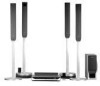
... connections, see page 29. Step 2: Connecting the System and TV This hookup is the basic connection of the system to 4 on the following pages. Front speaker (R) Center speaker Front speaker (L) AM loop antenna (aerial) AC power cord (mains lead) OUT (DVD ONLY) FRONT R FRONT L CENTER WOOFER SUR R SUR L SPEAKER TV/VCR2 OPTICAL DIGITAL IN DIGITAL IN COAXIAL...
... connections, see page 29. Step 2: Connecting the System and TV This hookup is the basic connection of the system to 4 on the following pages. Front speaker (R) Center speaker Front speaker (L) AM loop antenna (aerial) AC power cord (mains lead) OUT (DVD ONLY) FRONT R FRONT L CENTER WOOFER SUR R SUR L SPEAKER TV/VCR2 OPTICAL DIGITAL IN DIGITAL IN COAXIAL...
Operating Instructions
Page 17
...color tube of the speaker cords are reversed, the sound will lack bass and may be connected. Make sure the bare wire of each other than the one currently displayed on the Setup Display, the speaker may damage the system. If no sound is heard from a speaker while outputting a test... tone, or a test tone is touching another speaker terminal. For details on the components: 3 to 3, and # to follow these ...
...color tube of the speaker cords are reversed, the sound will lack bass and may be connected. Make sure the bare wire of each other than the one currently displayed on the Setup Display, the speaker may damage the system. If no sound is heard from a speaker while outputting a test... tone, or a test tone is touching another speaker terminal. For details on the components: 3 to 3, and # to follow these ...

Operating Instructions
Page 18
...TV sound or stereo sound of a 2 channel source from the plastic stand. 2 Set up the antenna (aerial). 1 Remove only the loop part from the 6 speakers, select the "Dolby Pro Logic," "Dolby Pro Logic II MOVIE," or "Dolby Pro Logic II MUSIC" sound field (page 37). 3 Connecting the Antenna (Aerial)...(aerial) is connected firmly by pulling softly. 18US Insert until this part. Note • Do not place the AM loop antenna (aerial) near the system or other AV equipment, as noise may result. A B AM Insert the cords pushing down the terminal clamp. Tip • When you want to ...
...TV sound or stereo sound of a 2 channel source from the plastic stand. 2 Set up the antenna (aerial). 1 Remove only the loop part from the 6 speakers, select the "Dolby Pro Logic," "Dolby Pro Logic II MOVIE," or "Dolby Pro Logic II MUSIC" sound field (page 37). 3 Connecting the Antenna (Aerial)...(aerial) is connected firmly by pulling softly. 18US Insert until this part. Note • Do not place the AM loop antenna (aerial) near the system or other AV equipment, as noise may result. A B AM Insert the cords pushing down the terminal clamp. Tip • When you want to ...
Operating Instructions
Page 19
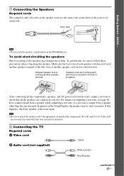
... FM antenna (aerial) 4 Connecting the AC power cord (mains lead) Before connecting the AC power cord (mains lead) of this system to a wall outlet (mains), connect the speakers to the COAXIAL FM 75 Ω jack. FM wire antenna (aerial) (supplied) FM wire antenna (aerial) (supplied) or COAXIAL FM 75...FM antenna (aerial) as possible. Tip • If you have poor FM reception, use a 75-ohm coaxial cable (not supplied) to connect the system to fully extend the FM wire antenna (aerial). • After connecting the FM wire antenna (aerial), keep it as horizontal as shown below. BASIC ...
... FM antenna (aerial) 4 Connecting the AC power cord (mains lead) Before connecting the AC power cord (mains lead) of this system to a wall outlet (mains), connect the speakers to the COAXIAL FM 75 Ω jack. FM wire antenna (aerial) (supplied) FM wire antenna (aerial) (supplied) or COAXIAL FM 75...FM antenna (aerial) as possible. Tip • If you have poor FM reception, use a 75-ohm coaxial cable (not supplied) to connect the system to fully extend the FM wire antenna (aerial). • After connecting the FM wire antenna (aerial), keep it as horizontal as shown below. BASIC ...

Operating Instructions
Page 20
...• When cleaning, use any type of the IR transmitter and IR receiver is poor, you can also connect the surround speakers to the system by the speaker cords (OPTION) (supplied). • When you change the settings. Extremely hot or cold - Subject to direct sunlight or strong... on or place objects other . Subject to 23 ft) (A) from the listening position (A). Step 3: Positioning the System Positioning the speakers For the best possible surround sound, all the speakers other than the subwoofer should be placed from 0.0 to 7.0 meters (0 to direct sunlight • Use caution when...
...• When cleaning, use any type of the IR transmitter and IR receiver is poor, you can also connect the surround speakers to the system by the speaker cords (OPTION) (supplied). • When you change the settings. Extremely hot or cold - Subject to direct sunlight or strong... on or place objects other . Subject to 23 ft) (A) from the listening position (A). Step 3: Positioning the System Positioning the speakers For the best possible surround sound, all the speakers other than the subwoofer should be placed from 0.0 to 7.0 meters (0 to direct sunlight • Use caution when...

Operating Instructions
Page 21
... (page 74). If this message does not appear, display the Quick Setup and perform again (page 22). 4 Press without inserting a disc. The system displays the menu and subtitles in the on the TV screen. [Press [ENTER] to run QUICK SETUP.] appears at the bottom of the screen. ... the Quick Setup Follow the steps below to make the minimum number of the TV to "DVD." 3 Switch the input selector on the surround amplifier. For details, see "Getting Optimal Surround Sound for selecting the speaker formation appears. 9 Press C/c to select a language. Getting Started - SCREEN SETUP TV TYPE: ...
... (page 74). If this message does not appear, display the Quick Setup and perform again (page 22). 4 Press without inserting a disc. The system displays the menu and subtitles in the on the TV screen. [Press [ENTER] to run QUICK SETUP.] appears at the bottom of the screen. ... the Quick Setup Follow the steps below to make the minimum number of the TV to "DVD." 3 Switch the input selector on the surround amplifier. For details, see "Getting Optimal Surround Sound for selecting the speaker formation appears. 9 Press C/c to select a language. Getting Started - SCREEN SETUP TV TYPE: ...

Operating Instructions
Page 22
... setup operations are complete. Tip • If you want to select [YES]. To recall the Quick Setup display 1 Press DISPLAY when the system is in the measurement area and making noise during the measurement. BASIC - 10 Connect the calibration mic to the A.CAL MIC jack on the...calibration mic at the ear level using a tripod, etc. (not supplied). Give consideration to select [YES], then press . The front of the speakers, reset the speaker settings. See "Getting Optimal Surround Sound for [SETUP] appear. 1 2 ( 2 7 ) 1 8 ( 3 4 ) : : DVD VIDEO QUICK QUICK CUSTOM RESET BNR
... setup operations are complete. Tip • If you want to select [YES]. To recall the Quick Setup display 1 Press DISPLAY when the system is in the measurement area and making noise during the measurement. BASIC - 10 Connect the calibration mic to the A.CAL MIC jack on the...calibration mic at the ear level using a tripod, etc. (not supplied). Give consideration to select [YES], then press . The front of the speakers, reset the speaker settings. See "Getting Optimal Surround Sound for [SETUP] appear. 1 2 ( 2 7 ) 1 8 ( 3 4 ) : : DVD VIDEO QUICK QUICK CUSTOM RESET BNR

Operating Instructions
Page 23
...Sony's wireless product. Move the IR transmitter and/or the surround speaker (L) so that there is made. 5 Press AMP MENU. To adjust the IR transmitter and IR receiver of the surround speaker (L) After connecting the speakers, surround amplifier, IR transmitter, and the AC power cords (mains leads), adjust the wireless system... for easy reorientation. The system and surround amplifier turn on the surround ...
...Sony's wireless product. Move the IR transmitter and/or the surround speaker (L) so that there is made. 5 Press AMP MENU. To adjust the IR transmitter and IR receiver of the surround speaker (L) After connecting the speakers, surround amplifier, IR transmitter, and the AC power cords (mains leads), adjust the wireless system... for easy reorientation. The system and surround amplifier turn on the surround ...

Operating Instructions
Page 25
...on a wall when: - As a plaster board wall is an obstruction between the IR transmitter and IR receiver of the speaker 2 Fasten the screws to be used. • Sony is not responsible for the wall material and strength. Getting Started - there is especially fragile, attach the screws securely to ...a beam and fasten them to 13/32 inch) 3 Hang the speakers on the screws. 4.6 mm (3/16 inch) 10 mm (13/32 ...
...on a wall when: - As a plaster board wall is an obstruction between the IR transmitter and IR receiver of the speaker 2 Fasten the screws to be used. • Sony is not responsible for the wall material and strength. Getting Started - there is especially fragile, attach the screws securely to ...a beam and fasten them to 13/32 inch) 3 Hang the speakers on the screws. 4.6 mm (3/16 inch) 10 mm (13/32 ...

Operating Instructions
Page 27
... D TV with HDMI* jack IN To HDMI* IN To HDMI* OUT To COMPONENT VIDEO OUT OUT (DVD ONLY) FRONT R FRONT L CENTER WOOFER SUR R SUR L SPEAKER TV/VCR2 OPTICAL DIGITAL IN DIGITAL IN COAXIAL TV/VCR1 DIR-T1 R AUDIO IN L VIDEO IN COMPONENT VIDEO... D. ADVANCED - Check the jacks of High-Definition Multimedia Interface Specifications. Connecting the video/HDMI* cords Sends a played back DVD image to D (HDMI). Getting Started - The system incorporates High-Definition Multimedia Interface (HDMITM) technology. TV Hookup (Advanced) Select a hookup suitable for the jacks on version ...
... D TV with HDMI* jack IN To HDMI* IN To HDMI* OUT To COMPONENT VIDEO OUT OUT (DVD ONLY) FRONT R FRONT L CENTER WOOFER SUR R SUR L SPEAKER TV/VCR2 OPTICAL DIGITAL IN DIGITAL IN COAXIAL TV/VCR1 DIR-T1 R AUDIO IN L VIDEO IN COMPONENT VIDEO... D. ADVANCED - Check the jacks of High-Definition Multimedia Interface Specifications. Connecting the video/HDMI* cords Sends a played back DVD image to D (HDMI). Getting Started - The system incorporates High-Definition Multimedia Interface (HDMITM) technology. TV Hookup (Advanced) Select a hookup suitable for the jacks on version ...

Operating Instructions
Page 31
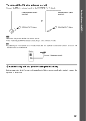
Other Component Hookup You can enjoy other component by connecting the VIDEO/AUDIO OUT jacks of this system Connect the VCR or other components to the TV/VCR1 or 2 (VIDEO IN/AUDIO IN) jacks using the video/audio cord (not supplied). When connecting a ... COAXIAL DIGITAL OUT VIDEO OUT AUDIO OUT L R To TV/VCR1 (VIDEO IN/AUDIO IN) To TV/VCR1 (DIGITAL IN COAXIAL) OUT (DVD ONLY) FRONT R FRONT L CENTER WOOFER SUR R SUR L SPEAKER TV/VCR2 OPTICAL DIGITAL IN DIGITAL IN COAXIAL TV/VCR1 DIR-T1 R AUDIO IN L VIDEO IN COMPONENT VIDEO IN Y PB/CB PR...
Other Component Hookup You can enjoy other component by connecting the VIDEO/AUDIO OUT jacks of this system Connect the VCR or other components to the TV/VCR1 or 2 (VIDEO IN/AUDIO IN) jacks using the video/audio cord (not supplied). When connecting a ... COAXIAL DIGITAL OUT VIDEO OUT AUDIO OUT L R To TV/VCR1 (VIDEO IN/AUDIO IN) To TV/VCR1 (DIGITAL IN COAXIAL) OUT (DVD ONLY) FRONT R FRONT L CENTER WOOFER SUR R SUR L SPEAKER TV/VCR2 OPTICAL DIGITAL IN DIGITAL IN COAXIAL TV/VCR1 DIR-T1 R AUDIO IN L VIDEO IN COMPONENT VIDEO IN Y PB/CB PR...

Operating Instructions
Page 36
...see page 37. Press MOVIE/MUSIC during playback. For details of a 2 channel source from the 6 speakers, select the "PRO LOGIC," "PLII MOVIE," or "PLII MUSIC" sound field. The default setting is displayed in this system. Press MOVIE/MUSIC repeatedly until the sound field you use both the TV/VCR 1 (AUDIO IN... want appears in the front panel display. SOUND FIELD Selecting the Movie or Music Mode You can enjoy TV or VCR sound from all the speakers in the front panel display. 36US repeatedly until "TV/VCR1" or "TV/VCR2" appears in the front panel display. 2 Press SOUND FIELD...
...see page 37. Press MOVIE/MUSIC during playback. For details of a 2 channel source from the 6 speakers, select the "PRO LOGIC," "PLII MOVIE," or "PLII MUSIC" sound field. The default setting is displayed in this system. Press MOVIE/MUSIC repeatedly until the sound field you use both the TV/VCR 1 (AUDIO IN... want appears in the front panel display. SOUND FIELD Selecting the Movie or Music Mode You can enjoy TV or VCR sound from all the speakers in the front panel display. 36US repeatedly until "TV/VCR1" or "TV/VCR2" appears in the front panel display. 2 Press SOUND FIELD...


