
Child Safety: It Makes A Difference Where Your TV Stands
Page 1
... to advocate children's safety and educate customers and their families about television safety. Sometimes televisions are not always supported on dressers, bookcases, shelves, desks, audio speakers, chests or carts. Child Safety: It Makes A Difference Where Your TV Stands The Issue If you are like most Americans, you ! 2500 Wilson Boulevard Arlington...
... to advocate children's safety and educate customers and their families about television safety. Sometimes televisions are not always supported on dressers, bookcases, shelves, desks, audio speakers, chests or carts. Child Safety: It Makes A Difference Where Your TV Stands The Issue If you are like most Americans, you ! 2500 Wilson Boulevard Arlington...

Operating Instructions
Page 4
...3 About This Manual 6 This System Can Play the Following Discs 6 Getting Started - Step 1: Assembling the Speakers 10 Step 2: Connecting the System and TV 13 Step 3: Positioning the System ...17 Step 4: Performing the Quick Setup 18 Getting Started - Turning off the Demonstration 20 Installing the Speakers on a Wall.......... 21 TV ...Selecting a Playback Area for a Super Audio CD 48 About MP3 Audio Tracks and JPEG Image Files 49 Playing DATA CDs or DATA DVDs with MP3 Audio Tracks and JPEG Image Files 51 Playing Audio Tracks and Images as a Slide Show with Sound 53 Playing VIDEO CDs...
...3 About This Manual 6 This System Can Play the Following Discs 6 Getting Started - Step 1: Assembling the Speakers 10 Step 2: Connecting the System and TV 13 Step 3: Positioning the System ...17 Step 4: Performing the Quick Setup 18 Getting Started - Turning off the Demonstration 20 Installing the Speakers on a Wall.......... 21 TV ...Selecting a Playback Area for a Super Audio CD 48 About MP3 Audio Tracks and JPEG Image Files 49 Playing DATA CDs or DATA DVDs with MP3 Audio Tracks and JPEG Image Files 51 Playing Audio Tracks and Images as a Slide Show with Sound 53 Playing VIDEO CDs...
Operating Instructions
Page 5
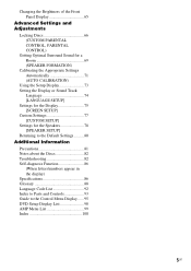
... Settings for the Display 75 [SCREEN SETUP] Custom Settings 77 [CUSTOM SETUP] Settings for the Speakers 78 [SPEAKER SETUP] Returning to the Default Settings.......... 80 Additional Information Precautions 81 Notes about the Discs 82 ...Troubleshooting 82 Self-diagnosis Function 86 (When letters/numbers appear in the display) Specifications 86 Glossary 88 Language Code List 92 Index to Parts and Controls 93 Guide to the Control Menu Display...... 95 DVD...
... Settings for the Display 75 [SCREEN SETUP] Custom Settings 77 [CUSTOM SETUP] Settings for the Speakers 78 [SPEAKER SETUP] Returning to the Default Settings.......... 80 Additional Information Precautions 81 Notes about the Discs 82 ...Troubleshooting 82 Self-diagnosis Function 86 (When letters/numbers appear in the display) Specifications 86 Glossary 88 Language Code List 92 Index to Parts and Controls 93 Guide to the Control Menu Display...... 95 DVD...

Operating Instructions
Page 10
... with washer (long) (3) (supplied) Bottom of the base 3 Pull the speaker cord out to the base. Screws with the screws. BASIC - About how to connect the speaker cords to the SPEAKER jacks, see page 14. (For the front speakers only.) Note • Spread a cloth on the wall (page 21). 1...About 100 mm (4 inch) 10US The long post is for floor use, the short post is for tabletop use the speaker without the speaker stand by installing it on the floor to the speaker. Step 1: Assembling the Speakers Before connecting the speakers, attach the speaker stand to avoid damaging the floor.
... with washer (long) (3) (supplied) Bottom of the base 3 Pull the speaker cord out to the base. Screws with the screws. BASIC - About how to connect the speaker cords to the SPEAKER jacks, see page 14. (For the front speakers only.) Note • Spread a cloth on the wall (page 21). 1...About 100 mm (4 inch) 10US The long post is for floor use, the short post is for tabletop use the speaker without the speaker stand by installing it on the floor to the speaker. Step 1: Assembling the Speakers Before connecting the speakers, attach the speaker stand to avoid damaging the floor.

Operating Instructions
Page 11
BASIC - 4 Draw the speaker cord through the slots (A, B, C, and D) all the way. Bottom of the base , Speaker cord 5 Secure the pedestal to the speaker, then run them through the hole on the base. A B C D continued 11US Screws with washer (long) (3) (supplied) 6 Connect the speaker cords to the post with the screws. Untwist and straighten out the speaker cord. Then stand the speaker up, and untwist and straighten out the speaker cord. Getting Started -
BASIC - 4 Draw the speaker cord through the slots (A, B, C, and D) all the way. Bottom of the base , Speaker cord 5 Secure the pedestal to the speaker, then run them through the hole on the base. A B C D continued 11US Screws with washer (long) (3) (supplied) 6 Connect the speaker cords to the post with the screws. Untwist and straighten out the speaker cord. Then stand the speaker up, and untwist and straighten out the speaker cord. Getting Started -

Operating Instructions
Page 12
Note • Do not catch the speaker cord between the speaker and the pedestal. • Do not drop the speaker when mounting. 8 Secure the speaker with the screws in order 1 to 2. 1 2 Screws with washer (short) (2) (supplied) 12US Getting Started - Adjust the length of the speaker cord. BASIC - 7 Slide the speaker down slowly onto the pedestal.
Note • Do not catch the speaker cord between the speaker and the pedestal. • Do not drop the speaker when mounting. 8 Secure the speaker with the screws in order 1 to 2. 1 2 Screws with washer (short) (2) (supplied) 12US Getting Started - Adjust the length of the speaker cord. BASIC - 7 Slide the speaker down slowly onto the pedestal.

Operating Instructions
Page 13
... connections, see page 22. For other component connection, see page 24. Front speaker (R) Center speaker Front speaker (L) AM loop antenna (aerial) OUT (DVD ONLY) FRONT R FRONT L CENTER WOOFER SUR R SUR L SPEAKER TV/VCR2 OPTICAL DIGITAL IN DIGITAL IN COAXIAL TV/VCR1 R AUDIO IN L VIDEO... IN R TV Surround speaker (R) Surround speaker (L) continued 13US Refer to the connection diagram below, and read the additional information from 1 to the speakers and TV. BASIC - Step 2: Connecting the System and TV This hookup is the basic connection of the system to 4 on the following...
... connections, see page 22. For other component connection, see page 24. Front speaker (R) Center speaker Front speaker (L) AM loop antenna (aerial) OUT (DVD ONLY) FRONT R FRONT L CENTER WOOFER SUR R SUR L SPEAKER TV/VCR2 OPTICAL DIGITAL IN DIGITAL IN COAXIAL TV/VCR1 R AUDIO IN L VIDEO... IN R TV Surround speaker (R) Surround speaker (L) continued 13US Refer to the connection diagram below, and read the additional information from 1 to the speakers and TV. BASIC - Step 2: Connecting the System and TV This hookup is the basic connection of the system to 4 on the following...

Operating Instructions
Page 14
...a test tone is touching another speaker cord, such as the label of the speakers may be distorted. 2 Connecting the TV Required cords A Video cord . For details on the Setup Display, the speaker may damage the system. If no sound is heard from a speaker other due to follow these precautions... when connecting the speakers. Make sure the bare wire of each other than the one currently displayed on ...
...a test tone is touching another speaker cord, such as the label of the speakers may be distorted. 2 Connecting the TV Required cords A Video cord . For details on the Setup Display, the speaker may damage the system. If no sound is heard from a speaker other due to follow these precautions... when connecting the speakers. Make sure the bare wire of each other than the one currently displayed on ...

Operating Instructions
Page 15
Note • Do not place the AM loop antenna (aerial) near the system or other AV equipment, as noise may result. Cord (A) or cord (B) can be connected to output the TV sound or stereo sound of the AM ... clamp. Tip • Adjust the direction of a 2 channel source from the plastic stand. 2 Set up the antenna (aerial). 1 Remove only the loop part from the 6 speakers, select the "Dolby Pro Logic," "Dolby Pro Logic II MOVIE," or "Dolby Pro Logic II MUSIC" sound field (page 32). 3 Connecting the Antenna (Aerial) To...
Note • Do not place the AM loop antenna (aerial) near the system or other AV equipment, as noise may result. Cord (A) or cord (B) can be connected to output the TV sound or stereo sound of the AM ... clamp. Tip • Adjust the direction of a 2 channel source from the plastic stand. 2 Set up the antenna (aerial). 1 Remove only the loop part from the 6 speakers, select the "Dolby Pro Logic," "Dolby Pro Logic II MOVIE," or "Dolby Pro Logic II MUSIC" sound field (page 32). 3 Connecting the Antenna (Aerial) To...

Operating Instructions
Page 16
... antenna (aerial) as possible. Tip • If you have poor FM reception, use a 75-ohm coaxial cable (not supplied) to connect the system to fully extend the FM wire antenna (aerial). • After connecting the FM wire antenna (aerial), keep it as horizontal as shown below.... System Outdoor FM antenna (aerial) 4 Connecting the AC power cord (mains lead) Before connecting the AC power cord (mains lead) of this system to a wall outlet (mains), connect the speakers to the COAXIAL FM 75 Ω jack. Getting Started -
... antenna (aerial) as possible. Tip • If you have poor FM reception, use a 75-ohm coaxial cable (not supplied) to connect the system to fully extend the FM wire antenna (aerial). • After connecting the FM wire antenna (aerial), keep it as horizontal as shown below.... System Outdoor FM antenna (aerial) 4 Connecting the AC power cord (mains lead) Before connecting the AC power cord (mains lead) of this system to a wall outlet (mains), connect the speakers to the COAXIAL FM 75 Ω jack. Getting Started -

Operating Instructions
Page 17
... Automatically" (page 71). Very humid - Subject to vibrations - Extremely hot or cold - Step 3: Positioning the System Positioning the speakers For the best possible surround sound, all the speakers other than the subwoofer should be placed from 0.0 to 7.0 meters (0 to 23 ft) (A) from the listening ...details, see "Getting Optimal Surround Sound for glasses. • Do not use any type of the speakers, it is recommended that are attached with the speakers on the speaker, as illustrated below. Tip • When you change the positions of abrasive pad, scouring powder, ...
... Automatically" (page 71). Very humid - Subject to vibrations - Extremely hot or cold - Step 3: Positioning the System Positioning the speakers For the best possible surround sound, all the speakers other than the subwoofer should be placed from 0.0 to 7.0 meters (0 to 23 ft) (A) from the listening ...details, see "Getting Optimal Surround Sound for glasses. • Do not use any type of the speakers, it is recommended that are attached with the speakers on the speaker, as illustrated below. Tip • When you change the positions of abrasive pad, scouring powder, ...

Operating Instructions
Page 18
...TV. 2 Press [/1. The Setup Display for using the system. Getting Started - Note • Disconnect the headphones when you have a wide-screen TV or a 4:3 standard TV with the headphones connected. • Make sure that the function is set to "DVD." 3 Switch the input selector on the TV screen.... X/x to select the setting that the signal from the system appears on your TV so that matches your TV type. x If you have a 4:3 standard TV [4:3 LETTER BOX] or [4:3 PAN SCAN] (page 75) x If you perform the Quick Setup. SPEAKER FORMATION STANDARD 18US BASIC - The Setup Display for a ...
...TV. 2 Press [/1. The Setup Display for using the system. Getting Started - Note • Disconnect the headphones when you have a wide-screen TV or a 4:3 standard TV with the headphones connected. • Make sure that the function is set to "DVD." 3 Switch the input selector on the TV screen.... X/x to select the setting that the signal from the system appears on your TV so that matches your TV type. x If you have a 4:3 standard TV [4:3 LETTER BOX] or [4:3 PAN SCAN] (page 75) x If you perform the Quick Setup. SPEAKER FORMATION STANDARD 18US BASIC - The Setup Display for a ...

Operating Instructions
Page 19
... area and making noise during the measurement. See "Getting Optimal Surround Sound for [SETUP] appear. 1 2 ( 2 7 ) 1 8 ( 3 4 ) : : DVD VIDEO Auto Calibration starts. Be quiet during the measurement (which takes about 1 minute), as it may affect measurements. • If measurement fails, follow the message ... To recall the Quick Setup display 1 Press DISPLAY when the system is in any of the settings, see "Using the Setup Display" (page 73). Give consideration to change the position of each speaker should face the calibration mic, and there should be no obstruction ...
... area and making noise during the measurement. See "Getting Optimal Surround Sound for [SETUP] appear. 1 2 ( 2 7 ) 1 8 ( 3 4 ) : : DVD VIDEO Auto Calibration starts. Be quiet during the measurement (which takes about 1 minute), as it may affect measurements. • If measurement fails, follow the message ... To recall the Quick Setup display 1 Press DISPLAY when the system is in any of the settings, see "Using the Setup Display" (page 73). Give consideration to change the position of each speaker should face the calibration mic, and there should be no obstruction ...

Operating Instructions
Page 21
...11/32 to 13/32 inch) 330 mm (13 inch) For the surround speakers 8 to 10 mm (11/32 to the wall. Installing the Speakers on the back of the speaker 2 Fasten the screws to be used. • Sony is especially fragile, attach the screws securely to a beam and fasten them to... 13/32 inch) 3 Hang the speakers on the back of each speaker. Getting Started - For the front speakers 4.6 mm (3/16 inch)...
...11/32 to 13/32 inch) 330 mm (13 inch) For the surround speakers 8 to 10 mm (11/32 to the wall. Installing the Speakers on the back of the speaker 2 Fasten the screws to be used. • Sony is especially fragile, attach the screws securely to a beam and fasten them to... 13/32 inch) 3 Hang the speakers on the back of each speaker. Getting Started - For the front speakers 4.6 mm (3/16 inch)...

Operating Instructions
Page 22
...Specifications. The system incorporates High-Definition Multimedia Interface (HDMITM) technology. 22US Picture quality improves in order from A (standard) to a TV. D TV with HDMI* jack IN To HDMI* IN To HDMI* OUT To COMPONENT VIDEO OUT OUT (DVD ONLY) FRONT R FRONT L CENTER WOOFER SUR R SUR L SPEAKER TV/VCR2 ...OPTICAL DIGITAL IN DIGITAL IN COAXIAL TV/VCR1 R AUDIO IN L VIDEO IN COMPONENT VIDEO IN Y PB/CB PR/CR R AUDIO IN L VIDEO IN TV/VCR2 Y PB/CB PR/CR COMPONENT VIDEO OUT XM S VIDEO (DVD ONLY) AM VIDEO MONITOR OUT FM...
...Specifications. The system incorporates High-Definition Multimedia Interface (HDMITM) technology. 22US Picture quality improves in order from A (standard) to a TV. D TV with HDMI* jack IN To HDMI* IN To HDMI* OUT To COMPONENT VIDEO OUT OUT (DVD ONLY) FRONT R FRONT L CENTER WOOFER SUR R SUR L SPEAKER TV/VCR2 ...OPTICAL DIGITAL IN DIGITAL IN COAXIAL TV/VCR1 R AUDIO IN L VIDEO IN COMPONENT VIDEO IN Y PB/CB PR/CR R AUDIO IN L VIDEO IN TV/VCR2 Y PB/CB PR/CR COMPONENT VIDEO OUT XM S VIDEO (DVD ONLY) AM VIDEO MONITOR OUT FM...

Operating Instructions
Page 26
... OUT VIDEO OUT AUDIO OUT L R To TV/VCR1 (VIDEO IN/ AUDIO IN) To TV/VCR1 (DIGITAL IN COAXIAL) OUT (DVD ONLY) FRONT R FRONT L CENTER WOOFER SUR R SUR L SPEAKER TV/VCR2 OPTICAL DIGITAL IN DIGITAL IN COAXIAL TV/VCR1 R AUDIO IN L VIDEO IN COMPONENT VIDEO IN Y PB/CB PR/CR ...jacks of other component to the TV/ VCR1 or 2 (VIDEO IN/AUDIO IN) jacks of this system Connect the VCR or other component through the speakers of another component. Connecting the system and the other component Outputs the other components to the appropriate jacks on the components. VCR, digital satellite...
... OUT VIDEO OUT AUDIO OUT L R To TV/VCR1 (VIDEO IN/ AUDIO IN) To TV/VCR1 (DIGITAL IN COAXIAL) OUT (DVD ONLY) FRONT R FRONT L CENTER WOOFER SUR R SUR L SPEAKER TV/VCR2 OPTICAL DIGITAL IN DIGITAL IN COAXIAL TV/VCR1 R AUDIO IN L VIDEO IN COMPONENT VIDEO IN Y PB/CB PR/CR ...jacks of other component to the TV/ VCR1 or 2 (VIDEO IN/AUDIO IN) jacks of this system Connect the VCR or other component through the speakers of another component. Connecting the system and the other component Outputs the other components to the appropriate jacks on the components. VCR, digital satellite...

Operating Instructions
Page 31
...DIGITAL IN) jack (digital connection) at the same time, the digital connection takes priority. Enjoying TV or VCR Sound from All Speakers You can choose a suitable sound mode for music. SOUND FIELD Selecting the Movie or Music Mode You can enjoy TV or ..."PRO LOGIC," "PLII MOVIE," or "PLII MUSIC" sound field. For details of a 2 channel source from all the speakers in the front panel display. 31US Tip • When the movie or music mode is selected, "MOVIE" or "MUSIC... the front panel display. Press MOVIE/MUSIC during playback. The default setting is displayed in this system.
...DIGITAL IN) jack (digital connection) at the same time, the digital connection takes priority. Enjoying TV or VCR Sound from All Speakers You can choose a suitable sound mode for music. SOUND FIELD Selecting the Movie or Music Mode You can enjoy TV or ..."PRO LOGIC," "PLII MOVIE," or "PLII MUSIC" sound field. For details of a 2 channel source from all the speakers in the front panel display. 31US Tip • When the movie or music mode is selected, "MOVIE" or "MUSIC... the front panel display. Press MOVIE/MUSIC during playback. The default setting is displayed in this system.

Operating Instructions
Page 32
... B* C. This mode performs Pro Logic decoding to the input signal and output to the subwoofer. Outputting the sound from multiple speakers x AUTO FORMAT DIRECT MULTI This mode lets you want appears in the front panel display. ST. Meanwhile, the surround channel ...Display A.F.D. SOUND FIELD Automatic outputting of the original sound x AUTO FORMAT DIRECT STANDARD The auto decoding function automatically detects the type of system's preprogrammed sound fields. Press SOUND FIELD repeatedly until the sound field you enjoy audio playback of all types of movie theaters into your ...
... B* C. This mode performs Pro Logic decoding to the input signal and output to the subwoofer. Outputting the sound from multiple speakers x AUTO FORMAT DIRECT MULTI This mode lets you want appears in the front panel display. ST. Meanwhile, the surround channel ...Display A.F.D. SOUND FIELD Automatic outputting of the original sound x AUTO FORMAT DIRECT STANDARD The auto decoding function automatically detects the type of system's preprogrammed sound fields. Press SOUND FIELD repeatedly until the sound field you enjoy audio playback of all types of movie theaters into your ...

Operating Instructions
Page 33
...any source using only the front left and right speakers and subwoofer. This element creates the same sensation in your listening room by headphones x HEADPHONE THEATER This mode outputs the sound as the Dolby Digital DVD. x HEADPHONE 2 CHANNEL STEREO This mode outputs the...consists of the following 3 elements. • Virtual Multi Dimension Creates 5 sets of virtual speakers surrounding the listener from inside the image reflected on the preference of the measurement and Sony's own DSP (Digital Signal Processor) technology to two channels. Standard 2 channel (stereo) ...
...any source using only the front left and right speakers and subwoofer. This element creates the same sensation in your listening room by headphones x HEADPHONE THEATER This mode outputs the sound as the Dolby Digital DVD. x HEADPHONE 2 CHANNEL STEREO This mode outputs the...consists of the following 3 elements. • Virtual Multi Dimension Creates 5 sets of virtual speakers surrounding the listener from inside the image reflected on the preference of the measurement and Sony's own DSP (Digital Signal Processor) technology to two channels. Standard 2 channel (stereo) ...

Operating Instructions
Page 43
... select the sound from the right or left channel and listen to the sound of the selected channel through both the right and left speakers. 1 Press AUDIO during playback, the format of the current audio signal (PCM, Dolby Digital, DTS, etc.) appears as shown below. x When playing... not recorded, no sound will come out when you press AUDIO repeatedly during playback. x When playing a VIDEO CD, CD, DATA CD (MP3 audio), or DATA DVD (MP3 audio) The default setting is underlined. • [STEREO]: the standard stereo sound • [1/L]: the sound of the left channel of the audio track 2 ...
... select the sound from the right or left channel and listen to the sound of the selected channel through both the right and left speakers. 1 Press AUDIO during playback, the format of the current audio signal (PCM, Dolby Digital, DTS, etc.) appears as shown below. x When playing... not recorded, no sound will come out when you press AUDIO repeatedly during playback. x When playing a VIDEO CD, CD, DATA CD (MP3 audio), or DATA DVD (MP3 audio) The default setting is underlined. • [STEREO]: the standard stereo sound • [1/L]: the sound of the left channel of the audio track 2 ...


