
Service Manual
Page 1
... SERVICE NOTES 1-1 [2] SPECIFICATIONS 1-2 [3] NAMES OF PARTS 1-3 CHAPTER 2. ADJUSTMENTS [1] CD Section 2-1 [2] TEST MODE 2-2 [3] Standard Specification of user-safety (Required by safety regulations in some countries) the set should be restored to its original condition and only parts identical to those specified be used . CONTENTS PRECAUTIONS FOR USING LEAD-FREE SOLDER CHAPTER 1. MECHANICAL DESCRIPTION [1] REMOVING AND REINSTALLING THE MAIN PARTS 3-1 [2] DISASSEMBLY 3-3 CHAPTER 4. S2603XLUH260/ MICRO COMPONENT SYSTEM MODEL XL-UH260 XL-UH260 Micro Component...
... SERVICE NOTES 1-1 [2] SPECIFICATIONS 1-2 [3] NAMES OF PARTS 1-3 CHAPTER 2. ADJUSTMENTS [1] CD Section 2-1 [2] TEST MODE 2-2 [3] Standard Specification of user-safety (Required by safety regulations in some countries) the set should be restored to its original condition and only parts identical to those specified be used . CONTENTS PRECAUTIONS FOR USING LEAD-FREE SOLDER CHAPTER 1. MECHANICAL DESCRIPTION [1] REMOVING AND REINSTALLING THE MAIN PARTS 3-1 [2] DISASSEMBLY 3-3 CHAPTER 4. S2603XLUH260/ MICRO COMPONENT SYSTEM MODEL XL-UH260 XL-UH260 Micro Component...
Service Manual
Page 2
Example: Indicates lead-free solder of this model employs lead-free solder. Parts No. XL-UH260 PRECAUTIONS FOR USING LEAD-FREE SOLDER 1. Using lead-free wire solder When fixing the PWB soldered with polarity indication on the tip of the soldering bit,it is higher than the lead wire solder by 40 C,and as required. If a different type of parts may be exceeded, remove the...
Example: Indicates lead-free solder of this model employs lead-free solder. Parts No. XL-UH260 PRECAUTIONS FOR USING LEAD-FREE SOLDER 1. Using lead-free wire solder When fixing the PWB soldered with polarity indication on the tip of the soldering bit,it is higher than the lead wire solder by 40 C,and as required. If a different type of parts may be exceeded, remove the...
Service Manual
Page 3
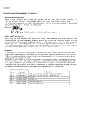
... lead dress to the user, perform the following manner. 0.15 µ F * Plug the AC line cord directly into a 120 volt AC outlet. * Using two clip leads, connect a 1.5k ohm, 10 watt resistor paralleled by a 0.15µF capacitor in series with all exposed metal cabinet parts and a known earth ground, such as insulating materials, cabinet, terminal board, adjustment and compartment covers...
... lead dress to the user, perform the following manner. 0.15 µ F * Plug the AC line cord directly into a 120 volt AC outlet. * Using two clip leads, connect a 1.5k ohm, 10 watt resistor paralleled by a 0.15µF capacitor in series with all exposed metal cabinet parts and a known earth ground, such as insulating materials, cabinet, terminal board, adjustment and compartment covers...
Service Manual
Page 4
XL-UH260 [2] SPECIFICATIONS General Power source Power consumption Dimensions Weight AC 120 V, 60 Hz 96 W Width: 6-3/4" (175 mm) Height: 9-1/2" (240 mm) Depth: 12-1/5" (315 mm) 12.4 lbs. (5.6 kg) Amplifier Output power Output terminals Input terminals 115 watts minimum RMS per channel into 6 ohms from 100 Hz to 20 kHz, 10% total harmonic distortion Speakers: 6 ohms Headphones: 16 - 50 ohms (recommended: 32 ohms) Subwoofer pre-out (audio signal): 200 mV/10 k ohms at 70 Hz...
XL-UH260 [2] SPECIFICATIONS General Power source Power consumption Dimensions Weight AC 120 V, 60 Hz 96 W Width: 6-3/4" (175 mm) Height: 9-1/2" (240 mm) Depth: 12-1/5" (315 mm) 12.4 lbs. (5.6 kg) Amplifier Output power Output terminals Input terminals 115 watts minimum RMS per channel into 6 ohms from 100 Hz to 20 kHz, 10% total harmonic distortion Speakers: 6 ohms Headphones: 16 - 50 ohms (recommended: 32 ohms) Subwoofer pre-out (audio signal): 200 mV/10 k ohms at 70 Hz...
Service Manual
Page 5
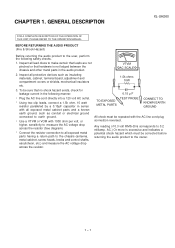
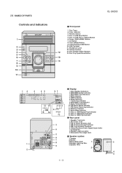
... (Audio Signal) Input Jacks 7. MP3/WMA Total Indicator 9. Daily Timer Indicator 13 14 9 10 11 10. Speaker Light-up Wire 5.Speaker Wire 2 4 5 1 - 35 FM Stereo Receiving Indicator 8 12. Disc or USB Repeat Play Indicator 15. Timer Indicator 3. Video/Auxiliary/USB Button 10. Disc Tray Open/Close Button 12 Display 3 45 67 1. Cooling Fan 8. Disc or USB Stop Button 5. USB Terminal 11. [3] NAMES OF PARTS Controls and indicators XL-UH260 Front panel 1. Subwoofer Pre-output Jack Speaker system 1.Tweeter 2.Woofer 3.Bass Reflex Duct 1 3 4.Speaker Light...
... (Audio Signal) Input Jacks 7. MP3/WMA Total Indicator 9. Daily Timer Indicator 13 14 9 10 11 10. Speaker Light-up Wire 5.Speaker Wire 2 4 5 1 - 35 FM Stereo Receiving Indicator 8 12. Disc or USB Repeat Play Indicator 15. Timer Indicator 3. Video/Auxiliary/USB Button 10. Disc Tray Open/Close Button 12 Display 3 45 67 1. Cooling Fan 8. Disc or USB Stop Button 5. USB Terminal 11. [3] NAMES OF PARTS Controls and indicators XL-UH260 Front panel 1. Subwoofer Pre-output Jack Speaker system 1.Tweeter 2.Woofer 3.Bass Reflex Duct 1 3 4.Speaker Light...

Service Manual
Page 6
...Remote control 1. Disc Number Select Buttons 3. Equalizer Mode Select Button 5. Volume Up and Down Buttons 7. Disc Play or Repeat Button 18. Tuning Down Button 23. CD Button 9. Disc Stop Button 14. Clock/Timer Button 1 - 46 CD Track Up or Fast Forward, Tuner Preset Up, Time Up Button 21. Disc Direct Search Buttons 4. USB Stop Button 15. Display Button 24. Remote Control Transmitter 2. Tuner (Band) Button 10. Disc/USB Pause Button 17. CD Track Down or Fast Reverse, Tuner Preset Down, Time Down Button 22. Extra Bass/Demo Button 6. Disc Random Button 13. Power...
...Remote control 1. Disc Number Select Buttons 3. Equalizer Mode Select Button 5. Volume Up and Down Buttons 7. Disc Play or Repeat Button 18. Tuning Down Button 23. CD Button 9. Disc Stop Button 14. Clock/Timer Button 1 - 46 CD Track Up or Fast Forward, Tuner Preset Up, Time Up Button 21. Disc Direct Search Buttons 4. USB Stop Button 15. Display Button 24. Remote Control Transmitter 2. Tuner (Band) Button 10. Disc/USB Pause Button 17. CD Track Down or Fast Reverse, Tuner Preset Down, Time Down Button 22. Extra Bass/Demo Button 6. Disc Random Button 13. Power...

Service Manual
Page 7
... detected for the 5th times. 2 - 1 XL-UH260 Each time a disc is detected, 'CHECKING' will be displayed instead of each disc can be 0 dB.) * Focus gain adjustment * Tracking gain adjustment 2. CD ERROR CODE DESCRIPTION Error 10* 11* 20* 21* Explanation CAM error. When it detect TRAY operation error during initialize process. When it detect cam operation error during initialize process. * 'CHECKING' If Error is changed, these adjustments are performed automatically. CHAPTER...
... detected for the 5th times. 2 - 1 XL-UH260 Each time a disc is detected, 'CHECKING' will be displayed instead of each disc can be 0 dB.) * Focus gain adjustment * Tracking gain adjustment 2. CD ERROR CODE DESCRIPTION Error 10* 11* 20* 21* Explanation CAM error. When it detect TRAY operation error during initialize process. When it detect cam operation error during initialize process. * 'CHECKING' If Error is changed, these adjustments are performed automatically. CHAPTER...
Service Manual
Page 8
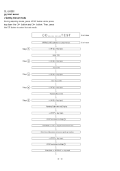
... 5 OPEN/CLOSE operation is using manual. > key input. Start Auto Adjustment at current pick-up location. Focus ON > key input. Laser ON. > key input. Then, press the CD button to Step 1 Everytime > key input IL isn't done IL isn't done 2 - 2 key input. STOP and return to Step 1 Hold down the 3 button and 4 button. XL-UH260 [2] TEST MODE • Setting the test mode During stand-by mode, press STOP button while pressing down...
... 5 OPEN/CLOSE operation is using manual. > key input. Start Auto Adjustment at current pick-up location. Focus ON > key input. Laser ON. > key input. Then, press the CD button to Step 1 Everytime > key input IL isn't done IL isn't done 2 - 2 key input. STOP and return to Step 1 Hold down the 3 button and 4 button. XL-UH260 [2] TEST MODE • Setting the test mode During stand-by mode, press STOP button while pressing down...
Service Manual
Page 9
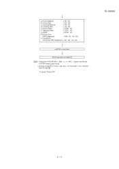
a) Focus Balance = FB : XX b) Focus Gain c) Tracking Balance = FG : XX = TB : XX d) Tracking Gain = TG : XX e) Focus Offset = FOFF : XX f) Tracking Offset g) RFRP = TOFF : XX = RFRP : XX h) Focus Error (RW Judgement) i) Focus Error = RW : XX - STOP and return to Step 1 Note Sliding the PICKUP with, > button can be set / >> for more than RW Judgement) = DA : XX - XX =XX (Other than 1 sec, it directly To cancel: Power OFF XL-UH260 2 - 3 XX =XX key input.
a) Focus Balance = FB : XX b) Focus Gain c) Tracking Balance = FG : XX = TB : XX d) Tracking Gain = TG : XX e) Focus Offset = FOFF : XX f) Tracking Offset g) RFRP = TOFF : XX = RFRP : XX h) Focus Error (RW Judgement) i) Focus Error = RW : XX - STOP and return to Step 1 Note Sliding the PICKUP with, > button can be set / >> for more than RW Judgement) = DA : XX - XX =XX (Other than 1 sec, it directly To cancel: Power OFF XL-UH260 2 - 3 XX =XX key input.
Service Manual
Page 10
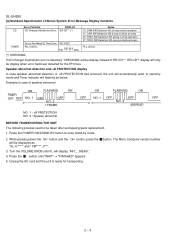
... Micro Computer version number 2 - 4 Turn the VOLUME KNOB until "WAIT"--> "FINISHED" appears. 5. button. Press the POWER ON/STAND-BY button to enter stand-by mode and Timer indicator will be display when error had occurred, the unit will display "INIT_ _MENU." 4. While pressing down the 3 button and the will flashing as "XL-U-****" and " FW****_V**". 4 button, press the 3. XL-UH260 [3] Standard Specification of speaker abnormal ON FLASHING ON TIMER...
... Micro Computer version number 2 - 4 Turn the VOLUME KNOB until "WAIT"--> "FINISHED" appears. 5. button. Press the POWER ON/STAND-BY button to enter stand-by mode and Timer indicator will be display when error had occurred, the unit will display "INIT_ _MENU." 4. While pressing down the 3 button and the will flashing as "XL-U-****" and " FW****_V**". 4 button, press the 3. XL-UH260 [3] Standard Specification of speaker abnormal ON FLASHING ON TIMER...

Service Manual
Page 57
... SDPB40F2A ECB KIA7805A XL-UH260 CHAPTER 6. As to change for improvement without any symbol is used : this symbol Pmeans pico-farad and the 1. microfarad. Besides, the one with "Fusible" is a fuse type. • Schematic diagram and Wiring Side of P.W.Board for this model are important for maintaining the safety (ML): Mylar type and performance of the set . (P.P.): Polypropylene type REF...
... SDPB40F2A ECB KIA7805A XL-UH260 CHAPTER 6. As to change for improvement without any symbol is used : this symbol Pmeans pico-farad and the 1. microfarad. Besides, the one with "Fusible" is a fuse type. • Schematic diagram and Wiring Side of P.W.Board for this model are important for maintaining the safety (ML): Mylar type and performance of the set . (P.P.): Polypropylene type REF...

Service Manual
Page 84
... CD player will automatically stop button. When the CD does not function The CD section may be used on car CD players or on the CD cleaner disc which has the mark next to the brush on computer CD-ROM drives. Turn the power off any adjustment make certain that the lens is dirty. CD optical pickup Lens cleaner disc Parts code UDSKA0004AFZZ...
... CD player will automatically stop button. When the CD does not function The CD section may be used on car CD players or on the CD cleaner disc which has the mark next to the brush on computer CD-ROM drives. Turn the power off any adjustment make certain that the lens is dirty. CD optical pickup Lens cleaner disc Parts code UDSKA0004AFZZ...

Service Manual
Page 85
... closed, "NO DISC" is loaded, start playback operation. 1. Yes 4. Is the turntable rotating ? No Press the Tray1 CD Eject Button without inserting a disc, and try starting the playback operation. 1 IC3 33 2 IC3 34 Sled motor (M2A). When a disc is displayed. 1. No If the level is accepted, but...played. 4.1. Check the laser diode driver Q1 peripheral circuit. No Pins 2, 3, 15 and 16 on IC1, Pins 1, 2, 15 and 16 on IC2 and pins 29 and 33 on IC3. Does the pickup move up and down ? (Waveform drawing Figure 1) Yes 3. XL-UH260 3. "NO MEDIA" is displayed. 1) Check the power...
... closed, "NO DISC" is loaded, start playback operation. 1. Yes 4. Is the turntable rotating ? No Press the Tray1 CD Eject Button without inserting a disc, and try starting the playback operation. 1 IC3 33 2 IC3 34 Sled motor (M2A). When a disc is displayed. 1. No If the level is accepted, but...played. 4.1. Check the laser diode driver Q1 peripheral circuit. No Pins 2, 3, 15 and 16 on IC1, Pins 1, 2, 15 and 16 on IC2 and pins 29 and 33 on IC3. Does the pickup move up and down ? (Waveform drawing Figure 1) Yes 3. XL-UH260 3. "NO MEDIA" is displayed. 1) Check the power...

Service Manual
Page 89
... with asterisk mark (*) is (open) terminal which is not connected to the outside. * Set power system GND to the minimum potential together with SGND * Short-circuit three pins of power system SVSS and PVCC1 externally before use. XL-UH260 8 - 1 OTHER [1] FUNCTION TABLE OF IC IC2 VHILA6261//-1: Focus/Tracking/Spin/Sled Driver (LA6261) Pin No. 1 2 3 4 5 6 7 8 9 10 11 12* 13 14...
... with asterisk mark (*) is (open) terminal which is not connected to the outside. * Set power system GND to the minimum potential together with SGND * Short-circuit three pins of power system SVSS and PVCC1 externally before use. XL-UH260 8 - 1 OTHER [1] FUNCTION TABLE OF IC IC2 VHILA6261//-1: Focus/Tracking/Spin/Sled Driver (LA6261) Pin No. 1 2 3 4 5 6 7 8 9 10 11 12* 13 14...

Service Manual
Page 91
... clock input pin for control. Volume + equaliser output pin Treble band filter comprising capacitor and resistor connection pin. Capacitor of "H" to be connected between VREF and AWSS (VSS) as a countermeasure against power ripple. Data written into an internal latch in a timing of several 10µF to "L". IC601 VHiLC75341/-1: Audio Processor (LC75341) XL-UH260 Pin No. Input selector output pin. Terminal Name Function 9-12 L4-1 Input signal pin...
... clock input pin for control. Volume + equaliser output pin Treble band filter comprising capacitor and resistor connection pin. Capacitor of "H" to be connected between VREF and AWSS (VSS) as a countermeasure against power ripple. Data written into an internal latch in a timing of several 10µF to "L". IC601 VHiLC75341/-1: Audio Processor (LC75341) XL-UH260 Pin No. Input selector output pin. Terminal Name Function 9-12 L4-1 Input signal pin...

Service Manual
Page 96
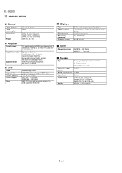
...) CS 14 SCK 15 SDATA 16 code write Serial data receive circuit Code/ command control circuit CGRAM dot data write (35bit x 16) code select XIN 21 XOUT 20 Clock generator timing clock Display controller scan pulse RESET 13 VCC1 19 VCC2 60 VSS 22 Vp 32 2 Figure 9 BLOCK DIAGRAM OF IC 8 - 8 Segment output circuit Segment/ Digit select/ output circuit 59 SEG00 33 SEG26 31 SEG27...
...) CS 14 SCK 15 SDATA 16 code write Serial data receive circuit Code/ command control circuit CGRAM dot data write (35bit x 16) code select XIN 21 XOUT 20 Clock generator timing clock Display controller scan pulse RESET 13 VCC1 19 VCC2 60 VSS 22 Vp 32 2 Figure 9 BLOCK DIAGRAM OF IC 8 - 8 Segment output circuit Segment/ Digit select/ output circuit 59 SEG00 33 SEG26 31 SEG27...
Service Manual
Page 110
... Cable,11Pin Connector Ass'y, Flat Cable Fuse Holder Fuse Holder Fuse Holder Fuse Holder Fuse Holder Fuse Holder Fuse Holder Fuse Holder Fuse Holder Fuse Holder FL Display Flat Wire,5 Pin Jack,Video/AUX Jack,Headphones Jack,USB Sub Woofer Output Lug Lug Lug Lug Relay,Power Relay,Speaker Remote Sensor,2013TH2E1 Terminal,Speaker Switch,Key Type [ DISC 4 ] Switch,Key Type [ DISC 5 ] Switch,Key Type [ OPEN/CLOSE ] Switch,Key Type [ DISC 1 ] Switch,Key Type [ DISC 2 ] Switch,Key Type [ DISC 3 ] Switch,Key Type [ POWER ON/STAND-BY ] Switch,Key Type [ PLAY/PAUSE ] Switch...
... Cable,11Pin Connector Ass'y, Flat Cable Fuse Holder Fuse Holder Fuse Holder Fuse Holder Fuse Holder Fuse Holder Fuse Holder Fuse Holder Fuse Holder Fuse Holder FL Display Flat Wire,5 Pin Jack,Video/AUX Jack,Headphones Jack,USB Sub Woofer Output Lug Lug Lug Lug Relay,Power Relay,Speaker Remote Sensor,2013TH2E1 Terminal,Speaker Switch,Key Type [ DISC 4 ] Switch,Key Type [ DISC 5 ] Switch,Key Type [ OPEN/CLOSE ] Switch,Key Type [ DISC 1 ] Switch,Key Type [ DISC 2 ] Switch,Key Type [ DISC 3 ] Switch,Key Type [ POWER ON/STAND-BY ] Switch,Key Type [ PLAY/PAUSE ] Switch...
Service Manual
Page 117
... Panel, Right AM Knob, VOLUME AC Bracket, PWB Support AA Nylon Band AD Bushing, AC Power Supply Cord AQ Chassis, Main AB Holder, Fuse AB Cushion, Leg AN Chassis, Changer Unit AD Holder, FL Display AC Holder, LED AC Holder, LED AA Nylon Band, 80mm AT Heat Sink, Main AL AC Power Supply Cord AC Lug (LG2-5) AR Label, Specification - PARTS CODE...
... Panel, Right AM Knob, VOLUME AC Bracket, PWB Support AA Nylon Band AD Bushing, AC Power Supply Cord AQ Chassis, Main AB Holder, Fuse AB Cushion, Leg AN Chassis, Changer Unit AD Holder, FL Display AC Holder, LED AC Holder, LED AA Nylon Band, 80mm AT Heat Sink, Main AL AC Power Supply Cord AC Lug (LG2-5) AR Label, Specification - PARTS CODE...
Service Manual
Page 121
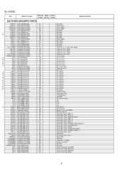
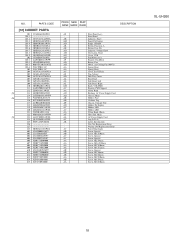
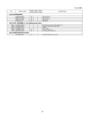
.../LedB4/SubB5 CD MP3 Speaker LED CD Motor (PWB Only) CD Changer Motor (PWB Only) [16] OTHER SERVICE PARTS UDSKA0004AFZZ AZ CD Optical Pickup Lens Cleaner Disc XL-UH260 22 PARTS CODE PRICE NEW PART RANK MARK RANK DESCRIPTION [14] ACCESSORIES QANTL0010AWZZ AP RRMCGA088AWSA AY TINSEA123AWZZ AD TINSZA183AWZZ AC 92LFANT1535A AF AM Loop Antenna Remote Control Operation Manual Quick Guide FM Antenna [15] P.W.B. ASSEMBLY ( Not Replacement Item ) PWB-A 92LPWB6480MANS...
.../LedB4/SubB5 CD MP3 Speaker LED CD Motor (PWB Only) CD Changer Motor (PWB Only) [16] OTHER SERVICE PARTS UDSKA0004AFZZ AZ CD Optical Pickup Lens Cleaner Disc XL-UH260 22 PARTS CODE PRICE NEW PART RANK MARK RANK DESCRIPTION [14] ACCESSORIES QANTL0010AWZZ AP RRMCGA088AWSA AY TINSEA123AWZZ AD TINSZA183AWZZ AC 92LFANT1535A AF AM Loop Antenna Remote Control Operation Manual Quick Guide FM Antenna [15] P.W.B. ASSEMBLY ( Not Replacement Item ) PWB-A 92LPWB6480MANS...
Service Manual
Page 122
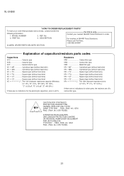
... lead wire) VR • • MN Cylindrical type (without lead wire) VR • • TV Square type (without lead wire) VR • • TQ Square type (without lead wire) VR • • CY Square type (without lead wire) VR • • CZ Square type (without lead wire) VC J .. XL-UH260 "HOW TO ORDER REPLACEMENT PARTS" To have your nearest SHARP Parts Distributor...
... lead wire) VR • • MN Cylindrical type (without lead wire) VR • • TV Square type (without lead wire) VR • • TQ Square type (without lead wire) VR • • CY Square type (without lead wire) VR • • CZ Square type (without lead wire) VC J .. XL-UH260 "HOW TO ORDER REPLACEMENT PARTS" To have your nearest SHARP Parts Distributor...


