
Service Manual
Page 1
... SYSTEM USB VIDEO /AUX USB XL-UH250 MODEL XL-UH250 XL-UH250 Micro Component System consisting of XL-UH250 (main unit) and CP-UH250 (speaker system). • In the interests of the set. ADJUSTMENTS [1] CD Section 2-1 [2] Test Mode 2-2 [3] Standard Specification Of Stereo System Error Message Display Contents 2-4 [4] CD Changer Mechanism Section 2-5 CHAPTER 3. CONTENTS PRECAUTIONS FOR USING LEAD-FREE SOLDER CHAPTER 1. FLOWCHART [1] Troubleshooting 7-1 CHAPTER 8. " are subject to those specified be used . GENERAL DESCRIPTION [1] Important Service Safety Precaution...
... SYSTEM USB VIDEO /AUX USB XL-UH250 MODEL XL-UH250 XL-UH250 Micro Component System consisting of XL-UH250 (main unit) and CP-UH250 (speaker system). • In the interests of the set. ADJUSTMENTS [1] CD Section 2-1 [2] Test Mode 2-2 [3] Standard Specification Of Stereo System Error Message Display Contents 2-4 [4] CD Changer Mechanism Section 2-5 CHAPTER 3. CONTENTS PRECAUTIONS FOR USING LEAD-FREE SOLDER CHAPTER 1. FLOWCHART [1] Troubleshooting 7-1 CHAPTER 8. " are subject to those specified be used . GENERAL DESCRIPTION [1] Important Service Safety Precaution...
Service Manual
Page 2
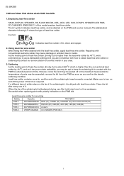
... (A1), POWER (A2), SPEAKER (A3), RE-FLASH MICOM (A4) PWB-B 92LPWB6656DPLS DISPLAY (B1), USB (B2), JACK (B3), LED (B4), SUB (B5) PWB-C 92LPWB6663CDUS CD MP3 PWB-D QPWBF1055AWZZ CD CHANGER (PWB ONLY) - 2i XL-UH250 AXSMEPeRuLardE-vMrMkiiCocePAPet1U1M55T00aIOnuNaSl FOR USING LEAD-FREE SOLDER 1. Using lead-free wire solder When fixing the PWB soldered with conventional lead wire solder may cause damage or accident due to turn on the...
... (A1), POWER (A2), SPEAKER (A3), RE-FLASH MICOM (A4) PWB-B 92LPWB6656DPLS DISPLAY (B1), USB (B2), JACK (B3), LED (B4), SUB (B5) PWB-C 92LPWB6663CDUS CD MP3 PWB-D QPWBF1055AWZZ CD CHANGER (PWB ONLY) - 2i XL-UH250 AXSMEPeRuLardE-vMrMkiiCocePAPet1U1M55T00aIOnuNaSl FOR USING LEAD-FREE SOLDER 1. Using lead-free wire solder When fixing the PWB soldered with conventional lead wire solder may cause damage or accident due to turn on the...

Service Manual
Page 3
... : "These servicing instructions are qualified to do so". Maximum total number of folders is 65 535. Supports ID3TAG version 1 and version 2. WARNING 1. Supports up to 20 kHz, 10% total harmonic distortion Speakers: 6 ohms Headphones: 16 - 50 ohms (recommended: 32 ohms) Subwoofer pre-out (audio signal): 200 mV/10 k ohms at 70 Hz Video/Auxiliary (audio signal): 500 mV/47 k ohms CD player Type Signal readout D/A converter Frequency response Dynamic range 5-disc multi-play compact disc player Non-contact...
... : "These servicing instructions are qualified to do so". Maximum total number of folders is 65 535. Supports ID3TAG version 1 and version 2. WARNING 1. Supports up to 20 kHz, 10% total harmonic distortion Speakers: 6 ohms Headphones: 16 - 50 ohms (recommended: 32 ohms) Subwoofer pre-out (audio signal): 200 mV/10 k ohms at 70 Hz Video/Auxiliary (audio signal): 500 mV/47 k ohms CD player Type Signal readout D/A converter Frequency response Dynamic range 5-disc multi-play compact disc player Non-contact...

Service Manual
Page 4
...Antenna Jack 4. Subwoofer Pre-output Jack Speaker system 1. Speaker Wire 1 3 2 4 1 - 24 Disc Tray Open/Close Button 12 3 45 67 13 14 15 16 9 10 11 8 12 Display 1. Disc or USB Pause Indicator 16. CD Button 8. Volume Control 13. MP3/WMA Folder Indicator 3. Daily Timer Indicator 10. Disc Number Select Buttons 14. MP3 Indicator 5. FM Stereo Receiving Indicator 12. Timer Indicator 3. MP3/WMA Title Indicators 4. Disc or USB Repeat Play Indicator 15. Video/Auxiliary (Audio Signal) Input Jacks 7. Sleep Indicator 7. Woofer 3. XL-UH250...
...Antenna Jack 4. Subwoofer Pre-output Jack Speaker system 1. Speaker Wire 1 3 2 4 1 - 24 Disc Tray Open/Close Button 12 3 45 67 13 14 15 16 9 10 11 8 12 Display 1. Disc or USB Pause Indicator 16. CD Button 8. Volume Control 13. MP3/WMA Folder Indicator 3. Daily Timer Indicator 10. Disc Number Select Buttons 14. MP3 Indicator 5. FM Stereo Receiving Indicator 12. Timer Indicator 3. MP3/WMA Title Indicators 4. Disc or USB Repeat Play Indicator 15. Video/Auxiliary (Audio Signal) Input Jacks 7. Sleep Indicator 7. Woofer 3. XL-UH250...
Service Manual
Page 5
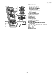
Remote Control Transmitter 2. Extra Bass/Demo Button 2 8 13 9 17 6. Power On/Stand-by Button 18 8. Tuner (Band) Button 14 10 19 10. Tuning Up Button 24 25 21. Tuning Down Button 24. Disc Number Select Buttons 11 15 3. Memory Button 16. USB Play or Repeat Button 3 20. Clock/Timer Button 1 - 35 Disc Direct Search Buttons 7 12 4. CD Button 9. USB Stop Button 15. Disc Pause Button 17. Disc Play or Repeat Button 18. USB Pause Button 22 23 19. CD Track Up or Fast...
Remote Control Transmitter 2. Extra Bass/Demo Button 2 8 13 9 17 6. Power On/Stand-by Button 18 8. Tuner (Band) Button 14 10 19 10. Tuning Up Button 24 25 21. Tuning Down Button 24. Disc Number Select Buttons 11 15 3. Memory Button 16. USB Play or Repeat Button 3 20. Clock/Timer Button 1 - 35 Disc Direct Search Buttons 7 12 4. CD Button 9. USB Stop Button 15. Disc Pause Button 17. Disc Play or Repeat Button 18. USB Pause Button 22 23 19. CD Track Up or Fast...

Service Manual
Page 6
....) * Focus gain adjustment * Tracking gain adjustment 2. XL-UH250 CHAPTER 2. CD SECTION • Adjustment Since this CD system incorporates the following automatic adjustment functions, readjustment is changed, these adjustments are performed automatically. Therefore, playback of 'ER-CD**'. 'ER-CD**' display will be displayed when error had been detected for the 5th times. 2 - 1 Items adjusted automatically 1) Offset adjustment (The offset voltage between the head amplifier output and the VREF...
....) * Focus gain adjustment * Tracking gain adjustment 2. XL-UH250 CHAPTER 2. CD SECTION • Adjustment Since this CD system incorporates the following automatic adjustment functions, readjustment is changed, these adjustments are performed automatically. Therefore, playback of 'ER-CD**'. 'ER-CD**' display will be displayed when error had been detected for the 5th times. 2 - 1 Items adjusted automatically 1) Offset adjustment (The offset voltage between the head amplifier output and the VREF...
Service Manual
Page 7
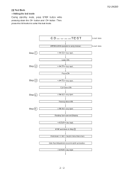
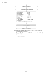
..., press the CD button to Step 1 Hold down the 3 button and 44 button. Start Auto Adjustment at current pick-up location. Focus ON > key input. STOP and return to enter the test mode.\ XL-UH250 Step 1 Step 2 Step 3 Step 4 Step 5 CD TE ST OPEN/CLOSE operation is using manual. > key input. IL isn't done IL isn't done 2 - 2 CLV Servo ON > key input. Reading Sub-code and Display key input.
..., press the CD button to Step 1 Hold down the 3 button and 44 button. Start Auto Adjustment at current pick-up location. Focus ON > key input. STOP and return to enter the test mode.\ XL-UH250 Step 1 Step 2 Step 3 Step 4 Step 5 CD TE ST OPEN/CLOSE operation is using manual. > key input. IL isn't done IL isn't done 2 - 2 CLV Servo ON > key input. Reading Sub-code and Display key input.
Service Manual
Page 8
XXXX i) Focus Error (Other than 1 sec, it directly To cancel: Power OFF 2 - 3 XXXX key input. STOP and return to Step 1 Everytime > key input a) Focus Balance = FB : XX b) Focus Gain = FG : XX c) Tracking Balance = TB : XX d) Tracking Gain = TG : XX e) Focus Offset = FOFF : XX f) Tracking Offset = TOFF : XX g) RFRP = RFRP : XX h) Focus Error (RW Judgement) = RW : XX - XL-UH250 STOP and return to Step 1 Note Sliding the PICKUP with , > button can be set / >> for more than RW Judgement) = DA : XX -
XXXX i) Focus Error (Other than 1 sec, it directly To cancel: Power OFF 2 - 3 XXXX key input. STOP and return to Step 1 Everytime > key input a) Focus Balance = FB : XX b) Focus Gain = FG : XX c) Tracking Balance = TB : XX d) Tracking Gain = TG : XX e) Focus Offset = FOFF : XX f) Tracking Offset = TOFF : XX g) RFRP = RFRP : XX h) Focus Error (RW Judgement) = RW : XX - XL-UH250 STOP and return to Step 1 Note Sliding the PICKUP with , > button can be set / >> for more than RW Judgement) = DA : XX -
Service Manual
Page 9
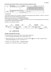
[3] Standard Specification Of Stereo System Error Message Display Contents XL-UH250 CD TUNER Error Contents DISPLAY CD Changer Mechanism Error. 'ER-CD**' (*) Focus Not Match/IL Time Over. 'NO DISC' PLL Unlock. Press the POWER ON/STAND-BY button to enter stand-by mode and Timer indicator will be display instead of speaker abnormal ON FLASHING ON TIMER LED OFF NO. 1 OFF OFF NO. 2 1 FRAME OFF ON NO. 1 FLASHING ON...
[3] Standard Specification Of Stereo System Error Message Display Contents XL-UH250 CD TUNER Error Contents DISPLAY CD Changer Mechanism Error. 'ER-CD**' (*) Focus Not Match/IL Time Over. 'NO DISC' PLL Unlock. Press the POWER ON/STAND-BY button to enter stand-by mode and Timer indicator will be display instead of speaker abnormal ON FLASHING ON TIMER LED OFF NO. 1 OFF OFF NO. 2 1 FRAME OFF ON NO. 1 FLASHING ON...

Service Manual
Page 53
... Schematic Diagram • Resistor: To differentiate the units of resistors, such symbol as K and M are important for this model are subject to replace these parts with " " ( ) are used : this symbol P means pico-farad and the unit of the set . In the tuner section, indicates AM indicates FM stereo 2. In the CD section, the CD is the one with no signal...
... Schematic Diagram • Resistor: To differentiate the units of resistors, such symbol as K and M are important for this model are subject to replace these parts with " " ( ) are used : this symbol P means pico-farad and the unit of the set . In the tuner section, indicates AM indicates FM stereo 2. In the CD section, the CD is the one with no signal...

Service Manual
Page 80
... optical pickup Lens cleaner disc Parts code UDSKA0004AFZZ HOW TO USE 1. Place the CD cleaner disc onto the CD disc tray with clean water and seek medical advice. In the event of isopropyl alcohol. Turn the power off any adjustment make certain that the lens is clean. If the CD cleaner brushes become worn out earlier then please replace the cleaner disc...
... optical pickup Lens cleaner disc Parts code UDSKA0004AFZZ HOW TO USE 1. Place the CD cleaner disc onto the CD disc tray with clean water and seek medical advice. In the event of isopropyl alcohol. Turn the power off any adjustment make certain that the lens is clean. If the CD cleaner brushes become worn out earlier then please replace the cleaner disc...

Service Manual
Page 81
...closed, "NO DISC" is displayed. 1) Check the power to IC2 ...diode driver Q1 peripheral circuit. data line. 3) Others. (1) Focus-RF system check. XL-UH250 Press the Tray1 CD Eject Button without inserting a disc, and try starting the playback operation....displayed. 1. Pressing the USB operation key is not normal. 1 FDO 9 IC1 5 RFO 89 IC1 4 TEI 6 IC1 Figure 2 5 IC1 89 RFO 7 - 2 Figure 3 No If the level is accepted, but playback data does not occur. 1) D+ data line. 2) D- When a disc is loaded, start playback operation. 1. Yes 4. When a USB cannot be played...
...closed, "NO DISC" is displayed. 1) Check the power to IC2 ...diode driver Q1 peripheral circuit. data line. 3) Others. (1) Focus-RF system check. XL-UH250 Press the Tray1 CD Eject Button without inserting a disc, and try starting the playback operation....displayed. 1. Pressing the USB operation key is not normal. 1 FDO 9 IC1 5 RFO 89 IC1 4 TEI 6 IC1 Figure 2 5 IC1 89 RFO 7 - 2 Figure 3 No If the level is accepted, but playback data does not occur. 1) D+ data line. 2) D- When a disc is loaded, start playback operation. 1. Yes 4. When a USB cannot be played...
Service Manual
Page 85
... (External PNP base). Reference voltage input pin. Power for channels 5 and 6 (H bridge). BTL Output pin (+) for tray motor. CHAPTER 8. H bridge Output pin (+) for tracking coil. BTL Output pin (-) for focus coil. Function BTL Output pin (+) for slide motor. BTL Output pin (-) for slide motor. BTL Output pin (+) for spin motor. CH5 Output change pin (FWD). H bridge Output pin (-) for gain control) CH5 Output change pin (REV).
... (External PNP base). Reference voltage input pin. Power for channels 5 and 6 (H bridge). BTL Output pin (+) for tray motor. CHAPTER 8. H bridge Output pin (+) for tracking coil. BTL Output pin (-) for focus coil. Function BTL Output pin (+) for slide motor. BTL Output pin (-) for slide motor. BTL Output pin (+) for spin motor. CH5 Output change pin (FWD). H bridge Output pin (-) for gain control) CH5 Output change pin (REV).

Service Manual
Page 88
... servo equalizer output pin. 11 VREF - Power supply pin for 3.3V digital circuit. 34 VDD1 - Grounding pin for 3.3V DSP VCO circuits. 15 VCOi Output PD output for VCO (control voltage input for Audio DAC. 30 Lo Output 3AI/F L channel audio output pin of Audio DAC. 28 DVDD3 - Reference voltage pin for VCO). 16 VDDP3 - Connect to TEL by 100kΩ when not in use , however , connect 3.3V...
... servo equalizer output pin. 11 VREF - Power supply pin for 3.3V digital circuit. 34 VDD1 - Grounding pin for 3.3V DSP VCO circuits. 15 VCOi Output PD output for VCO (control voltage input for Audio DAC. 30 Lo Output 3AI/F L channel audio output pin of Audio DAC. 28 DVDD3 - Reference voltage pin for VCO). 16 VDDP3 - Connect to TEL by 100kΩ when not in use , however , connect 3.3V...

Service Manual
Page 89
... mode. Connect 0.1uF. Connect 0.1uF. Power supply pin for active wide-range PLL. 71 PVDD3 - RF ripple signal input pin. Reference voltage output pin for 3.3V digital circuit. 53 VDDT3 - RF signal input pin Zin is selectable by command. EFM slice level output pin. LPF connection pin for RFEQO offset correction circuit. 8 - 5 XL-UH250 Default Remarks Input Schmitt input CMOS PORT Input Schmitt input CMOS PORT Input Output Output Output Output Output Input Schmitt input CMOS PORT For CD and DSP...
... mode. Connect 0.1uF. Connect 0.1uF. Power supply pin for active wide-range PLL. 71 PVDD3 - RF ripple signal input pin. Reference voltage output pin for 3.3V digital circuit. 53 VDDT3 - RF signal input pin Zin is selectable by command. EFM slice level output pin. LPF connection pin for RFEQO offset correction circuit. 8 - 5 XL-UH250 Default Remarks Input Schmitt input CMOS PORT Input Schmitt input CMOS PORT Input Output Output Output Output Output Input Schmitt input CMOS PORT For CD and DSP...

Service Manual
Page 90
... A. Sub beam signal input pin. Sub beam signal input pin. To be connected to PIN diode D. To be connected to PIN diode F. Monitor photodiode amplifier input pin. Main beam signal input pin. Note: The servo output pins (FOO, TRO, FMO, and DMO) become undefined or GND level under the following conditions: • /RST pin = Low • Crystal oscillation stopped according to place the system in standby mode while...
... A. Sub beam signal input pin. Sub beam signal input pin. To be connected to PIN diode D. To be connected to PIN diode F. Monitor photodiode amplifier input pin. Main beam signal input pin. Note: The servo output pins (FOO, TRO, FMO, and DMO) become undefined or GND level under the following conditions: • /RST pin = Low • Crystal oscillation stopped according to place the system in standby mode while...
Service Manual
Page 95
... replace these parts with " ! CONTENTS [1] INTEGRATED CIRCUITS [2] TRANSISTORS [3] DIODES [4] TRANSFORMERS [5] COILS [6] CRYSTALS / VIBRATORS [7] CAPACITORS [8] RESISTORS [9] OTHER CIRCUITRY PARTS [10] CHANGER MECHANISM / CD MECHANISM PARTS [11] CABINET PARTS [12] SPEAKER BOX PARTS [13] ACCESSORIES [14] P.W.B. Be sure to be used for maintaining the safety and performance of XL-UH250 (main unit) and CP-UH250 (speaker system). XL-UH250 PARTS GUIDE MICRO COMPONENT SYSTEM MODEL XL-UH250 XL-UH250 Micro Component System consisting of the set...
... replace these parts with " ! CONTENTS [1] INTEGRATED CIRCUITS [2] TRANSISTORS [3] DIODES [4] TRANSFORMERS [5] COILS [6] CRYSTALS / VIBRATORS [7] CAPACITORS [8] RESISTORS [9] OTHER CIRCUITRY PARTS [10] CHANGER MECHANISM / CD MECHANISM PARTS [11] CABINET PARTS [12] SPEAKER BOX PARTS [13] ACCESSORIES [14] P.W.B. Be sure to be used for maintaining the safety and performance of XL-UH250 (main unit) and CP-UH250 (speaker system). XL-UH250 PARTS GUIDE MICRO COMPONENT SYSTEM MODEL XL-UH250 XL-UH250 Micro Component System consisting of the set...

Service Manual
Page 104
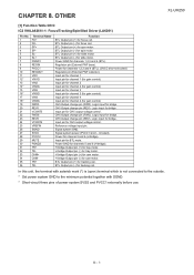
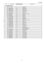
... Fuse Holder Fuse Holder Fuse Holder Fuse Holder Fuse Holder Fuse Holder Fuse Holder FL Display Flat Wire, 5 Pin Socket, VIDEO / AUX IN Headphone Jack USB Jack Socket, Sub Woofer Pre Out Lug Terminal Lug Terminal Lug Terminal Lug Terminal Lug Wire Relay,Power Relay Remote Sensor Speaker Jack Switch,Key Type [ DISC 4 ] Switch,Key Type [ DISC 5 ] Switch,Key Type [ OPEN/CLOSE ] Switch,Key Type [ DISC 1 ] Switch,Key Type [ DISC 2 ] Switch,Key Type [ DISC 3 ] Switch,Key Type [ POWER ON/STAND-BY ] Switch,Key Type [ PLAY/REPEAT ] Switch...
... Fuse Holder Fuse Holder Fuse Holder Fuse Holder Fuse Holder Fuse Holder Fuse Holder FL Display Flat Wire, 5 Pin Socket, VIDEO / AUX IN Headphone Jack USB Jack Socket, Sub Woofer Pre Out Lug Terminal Lug Terminal Lug Terminal Lug Terminal Lug Wire Relay,Power Relay Remote Sensor Speaker Jack Switch,Key Type [ DISC 4 ] Switch,Key Type [ DISC 5 ] Switch,Key Type [ OPEN/CLOSE ] Switch,Key Type [ DISC 1 ] Switch,Key Type [ DISC 2 ] Switch,Key Type [ DISC 3 ] Switch,Key Type [ POWER ON/STAND-BY ] Switch,Key Type [ PLAY/REPEAT ] Switch...
Service Manual
Page 109
... Side Panel, Right AM Knob, VOLUME AA Nylon Band AD Bushing, AC Power Supply Cord AP Chassis, Main AB Holder, Fuse AB Cushion, Leg AN Chassis, Changer Unit AD Holder, FL Display AC Holder, LED AC Holder, LED AA Nylon Band, 80mm AU Heat Sink, Main AN AC Power Supply Cord AC Lug (LG2-5) AC Label, Specification ---- PARTS CODE [11] CABINET PARTS...
... Side Panel, Right AM Knob, VOLUME AA Nylon Band AD Bushing, AC Power Supply Cord AP Chassis, Main AB Holder, Fuse AB Cushion, Leg AN Chassis, Changer Unit AD Holder, FL Display AC Holder, LED AC Holder, LED AA Nylon Band, 80mm AU Heat Sink, Main AN AC Power Supply Cord AC Lug (LG2-5) AC Label, Specification ---- PARTS CODE [11] CABINET PARTS...

Service Manual
Page 111
... RRMCGA120AWSA AR TINSKA025AWZZ AL FM Antenna AM Loop Antenna Remote Control Operation Manual [14] P.W.B. PWB-C 92LPWB6663CDUS - NO. PWB-D QPWBF1055AWZZ AE Main A1 / Power A2 / Speaker A3 / Re-Flash A4 Display B1 / USB B2 / Jack B3 / LED B4 / Sub B5 CD MP3 CD Changer Motor (PWB Only) [15] OTHER SERVICE PARTS UDSKA0004AFZZ AZ CD Optical Pickup Lens Cleaner Disc XL-UH250 16 PWB-A 92LPWB6656MANS - ASSEMBLY ( Not Replacement Item ) ! PWB-B 92LPWB6656DPLS...
... RRMCGA120AWSA AR TINSKA025AWZZ AL FM Antenna AM Loop Antenna Remote Control Operation Manual [14] P.W.B. PWB-C 92LPWB6663CDUS - NO. PWB-D QPWBF1055AWZZ AE Main A1 / Power A2 / Speaker A3 / Re-Flash A4 Display B1 / USB B2 / Jack B3 / LED B4 / Sub B5 CD MP3 CD Changer Motor (PWB Only) [15] OTHER SERVICE PARTS UDSKA0004AFZZ AZ CD Optical Pickup Lens Cleaner Disc XL-UH250 16 PWB-A 92LPWB6656MANS - ASSEMBLY ( Not Replacement Item ) ! PWB-B 92LPWB6656DPLS...


