
Service Manual
Page 1
... ...24 BLOCK DIAGRAM ...25 SCHEMATIC DIAGRAM ...30 WIRING SIDE OF P.W.BOARD ...45 WAVEFORMS OF 1-BIT CIRCUIT ...58 WAVEFORMS OF CD CIRCUIT ...59 CD OPTICAL PICKUP LENS CLEANING ...61 TROUBLESHOOTING ...61 FUNCTION TABLE OF IC ...66 CONNECTION OF EXTENSION CABLE ...79 FL DISPLAY ...84 PARTS GUIDE/EXPLODED VIEW SHARP CORPORATION - 1 - The contents are subject to those specified should be used . Illustration: SD-EX100 Illustration: SD-EX101 SD-EX100 SD-EX101 SERVICE MANUAL No.
... ...24 BLOCK DIAGRAM ...25 SCHEMATIC DIAGRAM ...30 WIRING SIDE OF P.W.BOARD ...45 WAVEFORMS OF 1-BIT CIRCUIT ...58 WAVEFORMS OF CD CIRCUIT ...59 CD OPTICAL PICKUP LENS CLEANING ...61 TROUBLESHOOTING ...61 FUNCTION TABLE OF IC ...66 CONNECTION OF EXTENSION CABLE ...79 FL DISPLAY ...84 PARTS GUIDE/EXPLODED VIEW SHARP CORPORATION - 1 - The contents are subject to those specified should be used . Illustration: SD-EX100 Illustration: SD-EX101 SD-EX100 SD-EX101 SERVICE MANUAL No.
Service Manual
Page 2
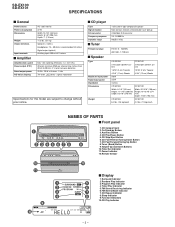
...-by Button 3. Tuner (Band) Button 9. Function Indicators 10.CD Play Indicator - 2 - FM Stereo Receiving Indicator 6. SD-EX100 SD-EX101 SPECIFICATIONS s General Power source Power consumption Dimensions Weight Output terminals Input terminals s Amplifier Amplification system Power output (FTC) Rated output power A/D noise shaping AC 120 V, 60 Hz 37 W Width: 13-1/8" (332 mm) Height: 8-1/8" (206 mm) Depth: 7" (178 mm) 11.2 lbs. (5.1 kg) Speakers: 4 ohms Headphones: 16 - 50 ohms (recommended: 32 ohms) Digital output (optical) Auxiliary input: 500 mV/47 k ohms 64fs 1-bit switching...
...-by Button 3. Tuner (Band) Button 9. Function Indicators 10.CD Play Indicator - 2 - FM Stereo Receiving Indicator 6. SD-EX100 SD-EX101 SPECIFICATIONS s General Power source Power consumption Dimensions Weight Output terminals Input terminals s Amplifier Amplification system Power output (FTC) Rated output power A/D noise shaping AC 120 V, 60 Hz 37 W Width: 13-1/8" (332 mm) Height: 8-1/8" (206 mm) Depth: 7" (178 mm) 11.2 lbs. (5.1 kg) Speakers: 4 ohms Headphones: 16 - 50 ohms (recommended: 32 ohms) Digital output (optical) Auxiliary input: 500 mV/47 k ohms 64fs 1-bit switching...

Service Manual
Page 3
... Mode Select Button 13.Time Display/Dimmer Button 5 16 14.CD Play/Pause Button 15.Preset Equalizer Button 17 16.CD Fast Forward/Tuning Up Button 6 17.Tuner (Band) Button 7 18 18.Enter Button 19.Extra Bass Button 20.CD/Tuner Direct Buttons 19 21.CD Time Display Button 8 Buttons with the speaker diaphragms when you remove the speaker grilles. Auxiliary Input Jacks 6 4. FM 75 Ohms Antenna Terminal 7. On/Stand-by Button 3. AM Antenna Terminal 9 s Speaker system 1. Bass Reflex Duct 5. AC Input Jack 2. Speaker Grille 2. CP-EX100 CP-EX101 s Remote control...
... Mode Select Button 13.Time Display/Dimmer Button 5 16 14.CD Play/Pause Button 15.Preset Equalizer Button 17 16.CD Fast Forward/Tuning Up Button 6 17.Tuner (Band) Button 7 18 18.Enter Button 19.Extra Bass Button 20.CD/Tuner Direct Buttons 19 21.CD Time Display Button 8 Buttons with the speaker diaphragms when you remove the speaker grilles. Auxiliary Input Jacks 6 4. FM 75 Ohms Antenna Terminal 7. On/Stand-by Button 3. AM Antenna Terminal 9 s Speaker system 1. Bass Reflex Duct 5. AC Input Jack 2. Speaker Grille 2. CP-EX100 CP-EX101 s Remote control...

Service Manual
Page 15
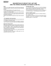
... CD system does not require readjustment after pickup replacement. Auto adjustment is stored in the preset memory as shown in auto adjustment of the speaker output terminal (JK400) is performed. The frequencies registered by the user will clear all the preset data. AC 120V Output Speaker Terminal + UNIT - VR : 0 JK400 Input:AUX Electric Voltmeter Figure 15-1 OUTPUT OFFSET LEVEL 1-BIT AMP. For details, refer to realize optimum playback...
... CD system does not require readjustment after pickup replacement. Auto adjustment is stored in the preset memory as shown in auto adjustment of the speaker output terminal (JK400) is performed. The frequencies registered by the user will clear all the preset data. AC 120V Output Speaker Terminal + UNIT - VR : 0 JK400 Input:AUX Electric Voltmeter Figure 15-1 OUTPUT OFFSET LEVEL 1-BIT AMP. For details, refer to realize optimum playback...
Service Manual
Page 16
... the trailing edge. For detailed technical description of 25 W output setting, the level is for SM-SX100 already published. Dead time and level shift When the 1-bit signals are output from BIA106 are input to feed back the signal through a low pass filter comprised of the unit. power sources. Dynamic feedback circuit The 1-bit signal switched by RA176, RA178, and RA180, respectively. The resistance...
... the trailing edge. For detailed technical description of 25 W output setting, the level is for SM-SX100 already published. Dead time and level shift When the 1-bit signals are output from BIA106 are input to feed back the signal through a low pass filter comprised of the unit. power sources. Dynamic feedback circuit The 1-bit signal switched by RA176, RA178, and RA180, respectively. The resistance...
Service Manual
Page 17
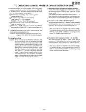
... shown in this model consecutively monitors the following errors 1 to 4 . Do not interrupt the PROTECT detection line of the microcomputer, if any error occurs, all power supply except for the one to drive the microcomputer is interrupted. 1 Abnormal output voltage drop of each regulator Connect the measuring apparatus (oscilloscope, etc.) to turn on the unit power for detecting speaker output DC voltage...
... shown in this model consecutively monitors the following errors 1 to 4 . Do not interrupt the PROTECT detection line of the microcomputer, if any error occurs, all power supply except for the one to drive the microcomputer is interrupted. 1 Abnormal output voltage drop of each regulator Connect the measuring apparatus (oscilloscope, etc.) to turn on the unit power for detecting speaker output DC voltage...

Service Manual
Page 18
... the PU_IN switch is stopped/ To display the error number during CD playback 7. CD FAST FORWARD (TUNING / ): Forcible shift in STEP 4 * Keep pressing the CD PLAY button for 1 second (75 frames) is displayed. Thereafter press the CD FAST FORWARD/REVERSE ( ) ( ) to select the TEST mode and then press the TUNER (BAND) button to STEP 5 directly. 2. SD-EX100 SD-EX101 TEST MODE From power off state to TEST mode Press the VOLUME DOWN button and...
... the PU_IN switch is stopped/ To display the error number during CD playback 7. CD FAST FORWARD (TUNING / ): Forcible shift in STEP 4 * Keep pressing the CD PLAY button for 1 second (75 frames) is displayed. Thereafter press the CD FAST FORWARD/REVERSE ( ) ( ) to select the TEST mode and then press the TUNER (BAND) button to STEP 5 directly. 2. SD-EX100 SD-EX101 TEST MODE From power off state to TEST mode Press the VOLUME DOWN button and...

Service Manual
Page 19
... AUX VOLUME UP VOLUME DOWN CD PLAY CD STOP CD FAST FORWARD CD FAST REVERSE [TUNER] kHz MHz PLAY [CD] STEREO RANDOM Segment 3. KEY test Pressing the E-START and VOLUME buttons simultaneously enables the key test mode. BUS2 is monitored in the idle mode and, in "H" status (sub code readable), number of errors per second (75 frames) is read the following preset stations. Readout of the adjusted value Press the DISPLAY button during...
... AUX VOLUME UP VOLUME DOWN CD PLAY CD STOP CD FAST FORWARD CD FAST REVERSE [TUNER] kHz MHz PLAY [CD] STEREO RANDOM Segment 3. KEY test Pressing the E-START and VOLUME buttons simultaneously enables the key test mode. BUS2 is monitored in the idle mode and, in "H" status (sub code readable), number of errors per second (75 frames) is read the following preset stations. Readout of the adjusted value Press the DISPLAY button during...
Service Manual
Page 20
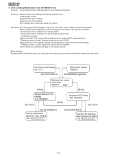
...EJECT] Mode select display "MECHA " [ERASE/BAND] ([BAND]) Mechanism test manual control mode "MECHA : " [Mode] [Mode] Aging mode w/o TOC reading "L/E N000000" [CD PLAY] [Mode] Aging mode with TOC reading: Repeatedly performs loading/TOC reading/ejection. Displays number of times. SD-EX100 SD-EX101 4. Maximum test counts are 100,000. Manual control mode: Manually controls mechanism according to test mechanism aging. Disc Loading Mechanism Test: CD MECHA Test Purpose: An operational check and aging test of disc loading mechanism Functions: Manual control of a mechanism...
...EJECT] Mode select display "MECHA " [ERASE/BAND] ([BAND]) Mechanism test manual control mode "MECHA : " [Mode] [Mode] Aging mode w/o TOC reading "L/E N000000" [CD PLAY] [Mode] Aging mode with TOC reading: Repeatedly performs loading/TOC reading/ejection. Displays number of times. SD-EX100 SD-EX101 4. Maximum test counts are 100,000. Manual control mode: Manually controls mechanism according to test mechanism aging. Disc Loading Mechanism Test: CD MECHA Test Purpose: An operational check and aging test of disc loading mechanism Functions: Manual control of a mechanism...
Service Manual
Page 21
... at a low speed when manually controlled. Lit after a CD is completed. Continuously Single press: the tray moves to distinguish between modes. Starts the selected aging test. Displayed for manual control. Continuous press: the tray moves toward the open position. SD-EX100 SD-EX101 Buttons to push ON/STAND-BY VOLUME UP VOLUME DOWN SKIP UP SKIP DOWN FUNCTION CD PLAY CD STOP/EJECT TUNER Main Remote unit control Operation [ON/STAND...
... at a low speed when manually controlled. Lit after a CD is completed. Continuously Single press: the tray moves to distinguish between modes. Starts the selected aging test. Displayed for manual control. Continuous press: the tray moves toward the open position. SD-EX100 SD-EX101 Buttons to push ON/STAND-BY VOLUME UP VOLUME DOWN SKIP UP SKIP DOWN FUNCTION CD PLAY CD STOP/EJECT TUNER Main Remote unit control Operation [ON/STAND...

Service Manual
Page 23
... to replace these parts with no signal given. 1. As to electrolytic capacitor, the expression "capacitance/withstand voltage" is used: this model are used . (CH), (TH), (RH), (UJ): Temperature compensation (ML): Mylar type (P.P.): Polypropylene type • Schematic diagram and Wiring Side of the set . FRONT VIEW GL3BC802 2647RT49 In the CD section, the CD is stopped. • Parts marked with "Fusible" is a fuse...
... to replace these parts with no signal given. 1. As to electrolytic capacitor, the expression "capacitance/withstand voltage" is used: this model are used . (CH), (TH), (RH), (UJ): Temperature compensation (ML): Mylar type (P.P.): Polypropylene type • Schematic diagram and Wiring Side of the set . FRONT VIEW GL3BC802 2647RT49 In the CD section, the CD is stopped. • Parts marked with "Fusible" is a fuse...
Service Manual
Page 26
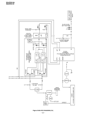
SECTION ANALOG SIGNAL INPUT NF ICA106/107 SLA5505M SWITCHING AUDIO POWER AMP. DEAD TIME CONTROL ICA110 TC74AC8T QUAD 2 INPUT AND GATE POWER - REF GND LEVEL SHIFT L-OUT L-IN H-OUT H-IN B. S OUT- OUT+ RESET NF- NF+ SLICE LEVEL SET VOLTAGE +5V OUTPUT OFFSET ADJUSTMENT ICA100 IX0498AW 7TH ORDER ∆∑ MODULATION CONVERSION LSI +B IN +POWER +POWER - POWER - S +5V L-OUT L-IN H-OUT H-IN B. SD-EX100 SD-EX101 AMP. POWER QA101 LOW PASS FILTER LOAD QA102 RL460 JK400 SPEAKER TERMINAL Q465...
SECTION ANALOG SIGNAL INPUT NF ICA106/107 SLA5505M SWITCHING AUDIO POWER AMP. DEAD TIME CONTROL ICA110 TC74AC8T QUAD 2 INPUT AND GATE POWER - REF GND LEVEL SHIFT L-OUT L-IN H-OUT H-IN B. S OUT- OUT+ RESET NF- NF+ SLICE LEVEL SET VOLTAGE +5V OUTPUT OFFSET ADJUSTMENT ICA100 IX0498AW 7TH ORDER ∆∑ MODULATION CONVERSION LSI +B IN +POWER +POWER - POWER - S +5V L-OUT L-IN H-OUT H-IN B. SD-EX100 SD-EX101 AMP. POWER QA101 LOW PASS FILTER LOAD QA102 RL460 JK400 SPEAKER TERMINAL Q465...

Service Manual
Page 61
... by pressing the / button. Is sound produced? Set the disc, power ON, and press the CD (STOP) button. No Yes Is output of IC701 Pin 19 (HF) flat in CD test mode 1? Yes Is music played from 1 to 2? Yes OFF ON The optical pickup in-switch is defective. (ON-state) Check the The optical microcomputer pickup in the wiring diagram? Before attempting any adjustment make certain that...
... by pressing the / button. Is sound produced? Set the disc, power ON, and press the CD (STOP) button. No Yes Is output of IC701 Pin 19 (HF) flat in CD test mode 1? Yes Is music played from 1 to 2? Yes OFF ON The optical pickup in-switch is defective. (ON-state) Check the The optical microcomputer pickup in the wiring diagram? Before attempting any adjustment make certain that...

Service Manual
Page 69
... amp input terminal Main beam amp input terminal Sub-beam amp input terminal Sub-beam amp input terminal Monitor photodiode amplifier input terminal Laser diode amp output terminal APC circuit ON/OFF signal, LDO terminal control input terminal and bottom/peak detection frequency switching terminal SEL APC circuit LDO GND OFF Connection to VCC via 1kΩ Hi-z ON Control signal output VCC ON Control signal output 9 TEBC 10 TEN 11 TEO 12 RFDC 13 GVSW Input Input Output Output Input Tracking error balance adjustment signal input...
... amp input terminal Main beam amp input terminal Sub-beam amp input terminal Sub-beam amp input terminal Monitor photodiode amplifier input terminal Laser diode amp output terminal APC circuit ON/OFF signal, LDO terminal control input terminal and bottom/peak detection frequency switching terminal SEL APC circuit LDO GND OFF Connection to VCC via 1kΩ Hi-z ON Control signal output VCC ON Control signal output 9 TEBC 10 TEN 11 TEO 12 RFDC 13 GVSW Input Input Output Output Input Tracking error balance adjustment signal input...

Service Manual
Page 70
... Input Inverting input terminal of amplifier for PLL low pass filter AI/F 19 LPFO Output Output terminal of S1 13 IO0 Input/Output General propose input-output terminal. SD-EX100 SD-EX101 IC702 VHiTC94A14F-1: Servo/Signal Control (TC94A14F) (1/2) Terminal Terminal Input/ No. "L" for Channel L, "H" for PLL low pass filter AI/F 20 PVREF - VREF Terminal exclusively for PLL 21 VCOF Output Filter terminal for VCO AI/F 22 AVSS3 - Name Output Function 1 BCK Output...
... Input Inverting input terminal of amplifier for PLL low pass filter AI/F 19 LPFO Output Output terminal of S1 13 IO0 Input/Output General propose input-output terminal. SD-EX100 SD-EX101 IC702 VHiTC94A14F-1: Servo/Signal Control (TC94A14F) (1/2) Terminal Terminal Input/ No. "L" for Channel L, "H" for PLL low pass filter AI/F 20 PVREF - VREF Terminal exclusively for PLL 21 VCOF Output Filter terminal for VCO AI/F 22 AVSS3 - Name Output Function 1 BCK Output...

Service Manual
Page 74
... bytes. Output Port processing. In this unit, the terminal with asterisk mark (*) is open terminal which is not connected to VSS 9 CNVSS FLASH_VCC Input Used in case of FLASH writing) Functionally unused. 18 P84/INT2 P_IN Input Power failure detection input Power failure detected according to FLASH writer) 32 P66/RXD1 (MD)MD_DATA FLASHRXD Input MD Data input serial 32 bytes. SD-EX100 SD-EX101 ICD02...
... bytes. Output Port processing. In this unit, the terminal with asterisk mark (*) is open terminal which is not connected to VSS 9 CNVSS FLASH_VCC Input Used in case of FLASH writing) Functionally unused. 18 P84/INT2 P_IN Input Power failure detection input Power failure detected according to FLASH writer) 32 P66/RXD1 (MD)MD_DATA FLASHRXD Input MD Data input serial 32 bytes. SD-EX100 SD-EX101 ICD02...

Service Manual
Page 75
... Timing with asterisk mark (*) is open terminal which is not connected to the outside. - 75 - "L" = TRY OPEN SW ON 62 VCC VCC Input The microcomputer power ON (3.3 V) Backup power supply 63 P30/A8(/-/D7) TRY_CL.SW Input CD Tray CLOSE SW detection input. ON: H 54 P40/A16 SP_RLY Output Speaker relay control. Port Name Terminal Name Input/Output Function 37 P61/CLK0 - SD-EX100 SD-EX101...
... Timing with asterisk mark (*) is open terminal which is not connected to the outside. - 75 - "L" = TRY OPEN SW ON 62 VCC VCC Input The microcomputer power ON (3.3 V) Backup power supply 63 P30/A8(/-/D7) TRY_CL.SW Input CD Tray CLOSE SW detection input. ON: H 54 P40/A16 SP_RLY Output Speaker relay control. Port Name Terminal Name Input/Output Function 37 P61/CLK0 - SD-EX100 SD-EX101...
Service Manual
Page 85
... ASSURER UNE LONGUE PROTECTION CONTRE UN INCENDIE, REMPLACER SEULEMENT PAR UN FUSIBLE DE TYPE F501,F502 8A, 125V/ F503 3A, 125V/F504 1.6A, 125V. PART NO. 4. PARTS GUIDE SD-EX100 SD-EX101 1-BIT DIGITAL AUDIO SYSTEM MODEL SD-EX100 SD-EX100 1-Bit Digital Audio System consisting of SD-EX101 (main unit) and CP-EX101 (speaker system). "HOW TO ORDER REPLACEMENT PARTS" To have your nearest SHARP Parts Distributor to replace parts with "1" are important...
... ASSURER UNE LONGUE PROTECTION CONTRE UN INCENDIE, REMPLACER SEULEMENT PAR UN FUSIBLE DE TYPE F501,F502 8A, 125V/ F503 3A, 125V/F504 1.6A, 125V. PART NO. 4. PARTS GUIDE SD-EX100 SD-EX101 1-BIT DIGITAL AUDIO SYSTEM MODEL SD-EX100 SD-EX100 1-Bit Digital Audio System consisting of SD-EX101 (main unit) and CP-EX101 (speaker system). "HOW TO ORDER REPLACEMENT PARTS" To have your nearest SHARP Parts Distributor to replace parts with "1" are important...
Service Manual
Page 92
... Carton,Speaker [SD-EX100] 92L8100109001 J Pad,Speaker [SD-EX100 Only] 92L8500040061 J Sheet,Speaker [SD-EX101] 92L8500040071 J Sheet,Speaker [SD-EX100] 92L8500045401 J Polyethylene Bag,Speaker ACCESSORIES ---- Battery,SUM-4 (Not Replacement Item) AS AM Loop Antenna BB Remote Control AD Registration Card AK Operation Manual AD FM Antenna AW Speaker Wire AM Leg Cushion,Speaker [SD-EX100] AN Leg Cushion,Speaker [SD-EX101] AK Quick Guide P.W.B. AB Spacer,Sensor Shield Case,A,D/A Converter Shield Case,B,D/A Converter AB Holder,Fuse...
... Carton,Speaker [SD-EX100] 92L8100109001 J Pad,Speaker [SD-EX100 Only] 92L8500040061 J Sheet,Speaker [SD-EX101] 92L8500040071 J Sheet,Speaker [SD-EX100] 92L8500045401 J Polyethylene Bag,Speaker ACCESSORIES ---- Battery,SUM-4 (Not Replacement Item) AS AM Loop Antenna BB Remote Control AD Registration Card AK Operation Manual AD FM Antenna AW Speaker Wire AM Leg Cushion,Speaker [SD-EX100] AN Leg Cushion,Speaker [SD-EX101] AK Quick Guide P.W.B. AB Spacer,Sensor Shield Case,A,D/A Converter Shield Case,B,D/A Converter AB Holder,Fuse...

Service Manual
Page 98
... TLABM0161AWSA Label,Caution TCAUZ0142AWZZ Label,Energy Star TLABZ0595AWZZ AC Power Supply Cord FM Antenna Polyethylene Bag,Accessories SSAKA0007AWZZ AM Loop Antenna Protection Sheet x2 SPAKZ0905AWZZ Label,Serial No. TLABN0215AWZZ Packing Add.,Left SPAKA0379AWZZ Remote Control Registration Card CABINET R SPEAKER FRONT Quick Guide Operation Manual Battery Pad,Spacer SPAKZ0897AWZZ : Not Replacement Item Packing Case SPAKC1495AWZZ [SD-EX100] SPAKC1501AWZZ [SD-EX101] Label,Bar Code TLABR1271AWZZ [SD-EX100] TLABR1287AWZZ [SD-EX101] - 13 -
... TLABM0161AWSA Label,Caution TCAUZ0142AWZZ Label,Energy Star TLABZ0595AWZZ AC Power Supply Cord FM Antenna Polyethylene Bag,Accessories SSAKA0007AWZZ AM Loop Antenna Protection Sheet x2 SPAKZ0905AWZZ Label,Serial No. TLABN0215AWZZ Packing Add.,Left SPAKA0379AWZZ Remote Control Registration Card CABINET R SPEAKER FRONT Quick Guide Operation Manual Battery Pad,Spacer SPAKZ0897AWZZ : Not Replacement Item Packing Case SPAKC1495AWZZ [SD-EX100] SPAKC1501AWZZ [SD-EX101] Label,Bar Code TLABR1271AWZZ [SD-EX100] TLABR1287AWZZ [SD-EX101] - 13 -


