
Sharp SD-EX101 Support Question
Sharp SD-EX101 Support Question
Find answers below for this question about Sharp SD-EX101.Need a Sharp SD-EX101 manual? We have 1 online manual for this item!
Question posted by Anonymous-126016 on December 3rd, 2013
Sharp Xd-a101 Won't Work
How do get the sharp ex-A101 to work when there is a letter P on the display and cash register won't work at all.
Current Answers
Related Sharp SD-EX101 Manual Pages
Service Manual - Page 1
...This document has been published to change without notice. MODEL SD-EX101
SD-EX101 1-Bit Digital Audio System consisting of SD-EX101 (main unit) and CP-EX101 (speaker system).
• In the interests of SD-EX100 (main unit) and CP-EX100 (speaker system). The...FUNCTION TABLE OF IC ...66 CONNECTION OF EXTENSION CABLE ...79 FL DISPLAY ...84 PARTS GUIDE/EXPLODED VIEW
SHARP CORPORATION - 1 -
Service Manual - Page 2
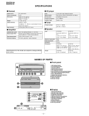
...s Display
1. FM Stereo Mode Indicator 7.
CD Play/Pause Button 5. Tuner (Band) Button 9. Program Play Indicator 4. Auxiliary Button 4. Function Indicators 10.CD Play Indicator
- 2 - SD-EX100 SD-EX101
SPECIFICATIONS...cm) Tweeter
4-3/8" (11 cm) Woofer
4-3/4" (12 cm) Woofer
50 W
25 W
4 ohms
CP-EX100
CP-EX101
Width: 6-1/8" (155 mm) Height: 11-1/16" (280 mm) Depth: 8-5/16" (210 mm)
Width: ...
Service Manual - Page 17
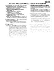
... voltage is over approx. 2 V of each regulator, components and board on the unit power switch. If the stabilized output is far smaller (below approx. 3 V) 2 Excessive output offset of BIA111, circuits IC570 and IC571 (for detecting speaker output DC voltage) may be abnormal.
SD-EX100 SD-EX101
TO CHECK AND CANCEL PROTECT CIRCUIT DETECTION LINE...
Service Manual - Page 26
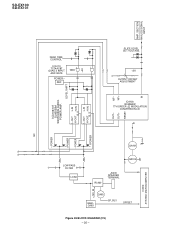
... SLA5505M SWITCHING AUDIO POWER AMP. S
OUT- POWER
QA101
LOW PASS FILTER
LOAD
QA102
RL460
JK400 SPEAKER TERMINAL
Q465
Q460~ Q463
SP_RLY
OFFSET
Figure 26 BLOCK DIAGRAM (2/5) - 26 -
+12V_M ICD02
SYSTEM MICROCOMPUTER
REF
GND
LEVEL SHIFT
L-OUT L-IN H-OUT H-IN
B. DEAD TIME CONTROL
ICA110 TC74AC8T QUAD 2 INPUT AND GATE
POWER - SD-EX100 SD-EX101
AMP...
Service Manual - Page 28

...14
MD/CD
L 12 R 13
23 5 20 6 19 VDD BASS TRE
IC301 LC75341M
AUDIO PROCESSOR
4 L-CH 21 R-CH
GND 3 1 2 24
IC330 NJM4558M OPE AMP.
-B ...HEADPHONE
Q337 Q338 MUTING
-12V(A) -B +12V(A)
+B
POWER SECTION DISPLAY SECTION
DISPLAY SECTION
H.P SW HEADPHONES
Figure 28 BLOCK DIAGRAM (4/5) - 28 - ...A_+12V TUN_L TUN_R
1-BIT AMP. SD-EX100 SD-EX101
FM 75ohms
SO101 GND ANTENNA TERMINAL GND
AM
FM OSC...
Service Manual - Page 29

...
A+12V
IC903 AN78L05
14
1
2
3
IC904 74VHC08F BUFFER AMP.
3.3V(D)
5
1
2
16
3
IC900 PCM1748E D/A CONVERTER
6
L7
R8
MD MC ML
13 14 15
SD-EX100 SD-EX101
2
1
6
7
IC901 NJM4580D LOW PASS FILTER
IC301 AUDIO PROCESSOR
FLD01 FL
ICD01 M66005 FL DRIVER
FL1 FL2
-Vp QD15
QD16
MAIN RLY
KEY1 KEY2
35 36 37
1 2 5 100
95 94...
Service Manual - Page 32

... ON SCHEMATIC DIAGRAM can be found on page 23.
1
2
3
4
5
Figure 32 SCHEMATIC DIAGRAM (3/15) - 32 -
SD-EX100 SD-EX101
DISPLAY PWB-A(2/2) A
ZD300 T/V_CK DZ10BSB
R313 1K T/V_CE
T/V_DI
B
1 2
C
3
4
5
6
R315 1K
C320 100/16...L1(CD/MD) R1 13
R301 1K
R302
IC301 1K
C301 LC75341M C302
2.2/50 AUDIO 2.2/50
PROCESSOR
R304 1K
C304 2.2/50
D300 DS1SS133
+B
L-CH
Q331 2SK246 GR
Q330...
Service Manual - Page 35

...Servo
Digital Equalizer RAM
Adjustment Circuit
ROM
A/D
Servo
Control
Digital Audio Out Output Circuit
Address Circuit
1BIT DAC
IC702
0.6V SBAD...F TO MOTOR PWB
7
8
9
10
11
12
Figure 35 SCHEMATIC DIAGRAM (6/15) - 35 - F FROM TERMINAL PWB
P44 1 - SD-EX100 SD-EX101
CNS402 P39 9 - B
FROM D/A CONVERTER PWB
C743 0.1
Q707 KRC101 M
2.1V 2
0V 3
1 0V
CD SIGNAL
0V
0V
0V
0V...
Service Manual - Page 61

...pickup return to 2? PWB. CD OPTICAL PICKUP LENS CLEANING
SD-EX100 SD-EX101
When the CD does not function
When the CD section ...cleaning solution so as not to 3? If the CD unit doesn't work
If objective lens for optical pickup is abnormal."
Yes
Is the voltage... matter on the laser pickup lens. When this section may be displayed. If not, clean it . (Be careful that a solution doesn...
Service Manual - Page 62

... side? No
Check connection of the optical pickup wire rods between Pins 5 and 6 of IC704? SD-EX100 SD-EX101
• Laser does not light up and down? No
Is the voltage of IC701? Is the ... of IC701. Normal
Is tracking input to Q701 collector?
Yes
IC701 defective. Yes
Check peripheral components of IC701 in CD test mode 4? If the rod is normal, the optical No pickup is...
Service Manual - Page 63

SD-EX100 SD-EX101
Does the thread motor operate in IC704 Pin 13? (See Waveform Figure 6 at P59.)
Yes
Are sawtooth waveforms generated... Pins 3 and 4 of BI702/CNS702? (See Waveform Figure 6 at P59.)
Yes
PWB patterns are not generated. Yes
Check defective peripheral components of + 3.3 V applied to Pins 11 and 17 of IC701 during track jump? (See Waveform Figure 4 at P59.)
Yes
Are triangular...
Service Manual - Page 64

...
5V
IC702 defective
0.3 to 1.5 seconds
Are eye patterns generated in CD test mode 3?
SD-EX100 SD-EX101
• Disc motor CLV servo is high voltage applied to Pin 41 of IC702 for approx...Are digital signals output from IC702 Pin 4 (Digital OUT)? No
Yes
IC702 defective (Check peripheral components to IC900 Pin 16? No
- 64 - No
Check connection of IC703. Yes
Is rotation excessively...
Service Manual - Page 65

... 2.0 V to IC702 Pin 40? Press the
/
button in the test mode. Yes
Are slide feed signals output between Pins 10 and 11 of IC702. Yes
SD-EX100 SD-EX101
Check defective peripheral components of IC704? • Sled motor does not operate.
If No OK, IC703 is defective.
Service Manual - Page 68
... terminal.
21
ROUT
Bass band filter capacitor/resistor connection terminal and bass/treble output terminal.
22
Vref
0.5 × VDD voltage generation section for analog ground.
SD-EX100 SD-EX101 IC301 VHiLC75341M-1: Audio Processor (LC75341M)
Pin No.
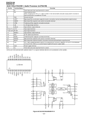
Service Manual - Page 70

...outside.
- 70 - "L" for Channel L, "H" for Channel R.
3-5I/F
Output polarity invertible by command
3
AOUT
Output Audio data output terminal.
3-5I/F
MSB/LSB First selectable by command
10*
DATA
Output Sub-code P - Zin selectable by command... Analog input Analog input Analog input SD-EX100 SD-EX101
IC702 VHiTC94A14F-1: Servo/Signal Control (TC94A14F) (1/2)
Terminal Terminal Input/
No.
Service Manual - Page 73

... latch enable input. Zero flag output for R-channel. Mode control clock input.
Audio data digital input. Analog power supply,+5V. Common voltage decoupling. SD-EX100 SD-EX101
(1) (1) (1)
(2) (2) (2)
AGND 9
VCOM 10
6 VCC ZEROR/ZEROA 11
5 VDD ZEROL/NA 12
MD 13
MC 14
ML 15
SCK 16
8 VOUTR
7 VOUTL
4 DGND
3 LRCK
2 DATA
1 BCK
...
Service Manual - Page 74

... "L".
20
P82/INT0
RX_IN
Input
Remote control input by SHARP system
21*
P81/TA4IN/U - Output Port processing.
Output...Name Input/Output
Function
1
P96/ANEX1/SOUT4 FLD_SDATA
Output Display data output to FL driver M66005
2
P95/ANEX0/...in single chip mode. Fixed at "L".
22*
P80/TA4OUT/U - SD-EX100 SD-EX101 ICD02 RH-iX0526AWZZ: System Microcomputer (IX0526AW) [To Serial No. 20x04000...
Service Manual - Page 78

...-side INB logic input.
13
HINB
High-side INB logic input.
14
VBOOTB
Bootstrap condenser terminal.
15
VBBB
Output stage power supply.
16*
N.C.
SD-EX100 SD-EX101 ICA106,ICA107 VHiSLA5505M-1: Switching Audio Power Amp. (SLA5505M)
Pin No.
Terminal Name
Function
1
SA
Output stage low-side source terminal.
2
OUTA
Output stage switching output.
3*
N.C. Unused.
17...
Service Manual - Page 85
...SD-EX100 SD-EX101
1-BIT DIGITAL AUDIO SYSTEM
MODEL SD-EX100
SD-EX100 1-Bit Digital Audio System consisting of SD-EX101 (main unit) and CP-EX101 (speaker system). MODEL SD-EX101
SD-EX101 1-Bit Digital Audio System consisting of SD... of the set . DESCRIPTION
For location of SHARP Parts Distributor,
Please call Toll-Free;
1-800-BE-SHARP
MARK: SPARE PARTS-DELIVERY SECTION
Explanation of the...
Service Manual - Page 100
SD-EX100 SD-EX101
COPYRIGHT © 2002 BY SHARP CORPORATION
ALL RIGHTS RESERVED. SHARP CORPORATION AV Systems Group Audio Systems Division Higashihiroshima, Hiroshima 739-0192, Japan
Printed in any form or by any means, electronic, mechanical, photocopying, recording, or otherwise, without prior written permission ...
Similar Questions

What Do I Do To Get My Tape Player To Work? It Want Play
what do I do to get my tape player to work?
what do I do to get my tape player to work?
(Posted by btwoodard1 1 year ago)

Stopped Working
please help! i received a sharp CD-DH950 for my birthday last July and recently it just stopped work...
please help! i received a sharp CD-DH950 for my birthday last July and recently it just stopped work...
(Posted by valchaulinux 11 years ago)

Screen Only Says 'good-bye' And Cd Player Won't Work
I have a year old Sharp CD-DH950. Cd player just stopped working, screen says "good-bye". I unplugge...
I have a year old Sharp CD-DH950. Cd player just stopped working, screen says "good-bye". I unplugge...
(Posted by kpstds 11 years ago)
Radio Not Working
just bought 2weeks ago and its a used one and radio not working,everythingelse works fine,no remote ...
just bought 2weeks ago and its a used one and radio not working,everythingelse works fine,no remote ...
(Posted by romeovalmeo 12 years ago)

Dosen't Work Anymore
All of a sudden the thing stopped working. Wont turn on wont do anything. Up until then was working ...
All of a sudden the thing stopped working. Wont turn on wont do anything. Up until then was working ...
(Posted by andrewcassidy23 12 years ago)