
Service Manual
Page 5
.../LED Drive Unit (LC-60LE810UN) TOUCH SENSOR Unit *2 LCD CONTROL Unit (LC-40LE810UN) LCD CONTROL Unit (LC-46LE810UN) LCD CONTROL Unit (LC-52LE810UN) LCD CONTROL Unit (LC-60LE810UN) LED PWB Unit (LC-40LE810UN), x4 LED PWB Unit (LC-46LE810UN), x4 LED PWB Unit (LC-52LE810UN), x4 LED PWB Unit (LC-60LE810UN), x4 LED PWB Unit (LC-60LE810UN), x4 Ref No. Part No. N N N N Part No. R1LK400D3LWF2Z R1LK460D3LWA2Z R1LK520D3LWA2Z R1LK600D3LW2BZ 40" LCD Panel...
.../LED Drive Unit (LC-60LE810UN) TOUCH SENSOR Unit *2 LCD CONTROL Unit (LC-40LE810UN) LCD CONTROL Unit (LC-46LE810UN) LCD CONTROL Unit (LC-52LE810UN) LCD CONTROL Unit (LC-60LE810UN) LED PWB Unit (LC-40LE810UN), x4 LED PWB Unit (LC-46LE810UN), x4 LED PWB Unit (LC-52LE810UN), x4 LED PWB Unit (LC-60LE810UN), x4 LED PWB Unit (LC-60LE810UN), x4 Ref No. Part No. N N N N Part No. R1LK400D3LWF2Z R1LK460D3LWA2Z R1LK520D3LWA2Z R1LK600D3LW2BZ 40" LCD Panel...
Service Manual
Page 17
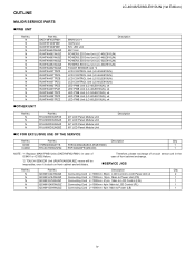
... 5 lock screws , 3 lock screws , 4 Hooks and detach the LCD Panel Module 3. Disconnect RA wire. 4. Detach the R/C, LED Unit . 3 4 LED Panel 5 Module 3 4 [RA] 3 3 3 Hook Hook LCD Fixing Metal Angle B-R 2 1 Hook Hook R/C, 8 [RA] [RK] LED Unit [RI] Front Cabinet Ass'y 7 ICON Unit 6 TOUCH SENSOR Unit 4 - 3 LC-40/46/52/60LE810UN (1st Edition) 3. Remove the 1 lock screw and detach the...
... 5 lock screws , 3 lock screws , 4 Hooks and detach the LCD Panel Module 3. Disconnect RA wire. 4. Detach the R/C, LED Unit . 3 4 LED Panel 5 Module 3 4 [RA] 3 3 3 Hook Hook LCD Fixing Metal Angle B-R 2 1 Hook Hook R/C, 8 [RA] [RK] LED Unit [RI] Front Cabinet Ass'y 7 ICON Unit 6 TOUCH SENSOR Unit 4 - 3 LC-40/46/52/60LE810UN (1st Edition) 3. Remove the 1 lock screw and detach the...
Service Manual
Page 19
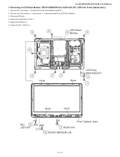
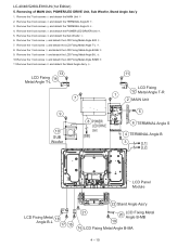
...detach the LCD Fixing Metal Angle T-R . 9. Remove the 2 lock screws and detach the TERMINAL Angle S . 4. LC-40/46/52/60LE810UN (1st Edition) 5. Remove the 6 lock screws and detach the POWER/LED DRIVER Unit . 5. Remove the 2 lock screws and detach the TERMINAL Angle B . 3. Remove the 1 lock ... T-L 18 VESA Angle 12 15 11 16 LCD Fixing Metal Angle T-R 9 7 1 2 MAIN Unit 10 SUB Woofer 8 POWER/ LED [SB] DRIVE Unit 5 6 TERMINAL Angle S 4 TERMINAL Angle B 3 [L1] [L2] LED Panel Module LCD Fixing 14 Metal Angle B-L 13 19 20 Stand Angle Ass'y 4 - 5 Removing of MAIN Unit, POWER...
...detach the LCD Fixing Metal Angle T-R . 9. Remove the 2 lock screws and detach the TERMINAL Angle S . 4. LC-40/46/52/60LE810UN (1st Edition) 5. Remove the 6 lock screws and detach the POWER/LED DRIVER Unit . 5. Remove the 2 lock screws and detach the TERMINAL Angle B . 3. Remove the 1 lock ... T-L 18 VESA Angle 12 15 11 16 LCD Fixing Metal Angle T-R 9 7 1 2 MAIN Unit 10 SUB Woofer 8 POWER/ LED [SB] DRIVE Unit 5 6 TERMINAL Angle S 4 TERMINAL Angle B 3 [L1] [L2] LED Panel Module LCD Fixing 14 Metal Angle B-L 13 19 20 Stand Angle Ass'y 4 - 5 Removing of MAIN Unit, POWER...
Service Manual
Page 22
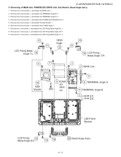
...] 3 3 Front Cabinet Ass'y Hook Hook LCD Fixing 2 Metal Angle B-R 1 Hook Hook R/C, 8 LED Unit [RA] [RK] [RI] 7 ICON Unit 6 TOUCH SENSOR Unit 4 - 8 Removing of LCD Panel Module, TOUCH SENSOR Unit, ICON Unit, R/C, LED Unit, Front Cabinet Ass'y. 1. Disconnect RA wire. 4. LC-40/46/52/60LE810UN (1st Edition) 3. Detach the ICON Unit . 6. Remove the 5 lock screws , 5 lock...
...] 3 3 Front Cabinet Ass'y Hook Hook LCD Fixing 2 Metal Angle B-R 1 Hook Hook R/C, 8 LED Unit [RA] [RK] [RI] 7 ICON Unit 6 TOUCH SENSOR Unit 4 - 8 Removing of LCD Panel Module, TOUCH SENSOR Unit, ICON Unit, R/C, LED Unit, Front Cabinet Ass'y. 1. Disconnect RA wire. 4. LC-40/46/52/60LE810UN (1st Edition) 3. Detach the ICON Unit . 6. Remove the 5 lock screws , 5 lock...
Service Manual
Page 24
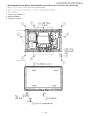
...and detach the TERMINAL Angle B . 3. Remove the 2 lock screws and detach the TERMINAL Angle S . 4. Remove the 6 lock screws and detach the POWER/LED DRIVER Unit . 5. Remove the 7 lock screws and detach the MAIN Unit 2. Remove the 1 lock screw and detach the LCD Fixing Metal Angle B-R . 7....Panel Module 22 Stand Angle Ass'y LCD Fixing Metal 18 Angle B-L 17 15 21 20 LCD Fixing Metal Angle B-MB 19 16 LCD Fixing Metal Angle B-MA 4 - 10 Remove the 4 lock screws and detach the Sub Woofer . 6. Remove the 1 lock screw and detach the LCD Fixing Metal Angle T-L . 8. LC-40/46/52/60LE810UN...
...and detach the TERMINAL Angle B . 3. Remove the 2 lock screws and detach the TERMINAL Angle S . 4. Remove the 6 lock screws and detach the POWER/LED DRIVER Unit . 5. Remove the 7 lock screws and detach the MAIN Unit 2. Remove the 1 lock screw and detach the LCD Fixing Metal Angle B-R . 7....Panel Module 22 Stand Angle Ass'y LCD Fixing Metal 18 Angle B-L 17 15 21 20 LCD Fixing Metal Angle B-MB 19 16 LCD Fixing Metal Angle B-MA 4 - 10 Remove the 4 lock screws and detach the Sub Woofer . 6. Remove the 1 lock screw and detach the LCD Fixing Metal Angle T-L . 8. LC-40/46/52/60LE810UN...
Service Manual
Page 27
... Cabinet Ass'y Hook Hook Hook Hook R/C, 8 [RA] LED Unit [RK] [RI] 7 ICON Unit 6 TOUCH SENSOR Unit 4 - 13 Detach the Touch Sensor Unit . 5. Remove the 1 lock screw and detach the LCD Fixing Metal Angle B-R . 2. Removing of LCD Panel Module, TOUCH SENSOR Unit, ICON Unit, R/C, LED Unit, Front Cabinet Ass'y. 1. LC-40/46/52/60LE810UN (1st Edition) 3.
... Cabinet Ass'y Hook Hook Hook Hook R/C, 8 [RA] LED Unit [RK] [RI] 7 ICON Unit 6 TOUCH SENSOR Unit 4 - 13 Detach the Touch Sensor Unit . 5. Remove the 1 lock screw and detach the LCD Fixing Metal Angle B-R . 2. Removing of LCD Panel Module, TOUCH SENSOR Unit, ICON Unit, R/C, LED Unit, Front Cabinet Ass'y. 1. LC-40/46/52/60LE810UN (1st Edition) 3.
Service Manual
Page 29
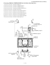
... . 13 LCD Fixing 14 Metal Angle T-L 9 10 SUB Woofer 11 7 8 POWER/ LED DRIVE [SB] Unit LCD Fixing 1 12 Metal Angle T-R 2 MAIN Unit 5 6 TERMINAL Angle S 4 TERMINAL Angle B 3 [L1] [L2] LCD Panel Module LCD Fixing Metal 18 22 Angle B-L 17 16 15 Stand Angle Ass'y LCD Fixing ...1 lock screw and detach the LCD Fixing Metal Angle T-L . 8. LC-40/46/52/60LE810UN (1st Edition) 5. Remove the 4 lock screws and detach the Sub Woofer . 6. Remove the 2 lock screws and detach the TERMINAL Angle B . 3. Removing of MAIN Unit, POWER/LED DRIVE Unit, Sub Woofer, Stand Angle Ass'y 1. Remove the 7 ...
... . 13 LCD Fixing 14 Metal Angle T-L 9 10 SUB Woofer 11 7 8 POWER/ LED DRIVE [SB] Unit LCD Fixing 1 12 Metal Angle T-R 2 MAIN Unit 5 6 TERMINAL Angle S 4 TERMINAL Angle B 3 [L1] [L2] LCD Panel Module LCD Fixing Metal 18 22 Angle B-L 17 16 15 Stand Angle Ass'y LCD Fixing ...1 lock screw and detach the LCD Fixing Metal Angle T-L . 8. LC-40/46/52/60LE810UN (1st Edition) 5. Remove the 4 lock screws and detach the Sub Woofer . 6. Remove the 2 lock screws and detach the TERMINAL Angle B . 3. Removing of MAIN Unit, POWER/LED DRIVE Unit, Sub Woofer, Stand Angle Ass'y 1. Remove the 7 ...
Service Manual
Page 32
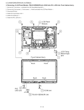
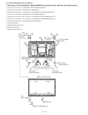
... LCD Fixing Metal Angle T-R . 6. Detach the Touch Sensor Unit . 10.Detach the ICON Unit . 11.Detach the R/C, LED Unit . 15 LCD 13 15 Fixing Metal Angle B-L 16 11 10 16 17 LCD Panel Module LCD Fixing Metal 12 Angle T-R 16 [RA] LCD Fixing Metal Angle B-L 9 4 Stand Angle 8 7 56 3... Metal Angle B-L . 5. Remove the 1 lock screw and detach the LCD Fixing Metal Angle B-R . 2. Remove the 9 lock screws and detach the LCD Panel Module . 8. Removing of LCD Panel Module, TOUCH SENSOR Unit, ICON Unit, R/C, LED Unit, Front Cabinet Ass'y. 1. LC-40/46/52/60LE810UN (1st Edition) 3.
... LCD Fixing Metal Angle T-R . 6. Detach the Touch Sensor Unit . 10.Detach the ICON Unit . 11.Detach the R/C, LED Unit . 15 LCD 13 15 Fixing Metal Angle B-L 16 11 10 16 17 LCD Panel Module LCD Fixing Metal 12 Angle T-R 16 [RA] LCD Fixing Metal Angle B-L 9 4 Stand Angle 8 7 56 3... Metal Angle B-L . 5. Remove the 1 lock screw and detach the LCD Fixing Metal Angle B-R . 2. Remove the 9 lock screws and detach the LCD Panel Module . 8. Removing of LCD Panel Module, TOUCH SENSOR Unit, ICON Unit, R/C, LED Unit, Front Cabinet Ass'y. 1. LC-40/46/52/60LE810UN (1st Edition) 3.
Service Manual
Page 34
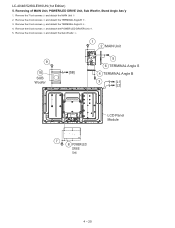
Remove the 6 lock screws and detach the POWER/LED DRIVER Unit . 5. Removing of MAIN Unit, POWER/LED DRIVE Unit, Sub Woofer, Stand Angle Ass'y 1. Remove the 2 lock screws and detach the TERMINAL Angle S . 4. Remove the 2 lock screws and detach the TERMINAL Angle B . 3. Remove the 7 lock screws and detach the MAIN Unit 2. Remove the 4 lock screws and detach the Sub Woofer . 1 2 MAIN Unit 9 10 [SB] SUB Woofer 5 6 TERMINAL Angle S 4 TERMINAL Angle B 3 [L1] [L2] 7 8 POWER/LED DRIVE Unit LCD Panel Module 4 - 20 LC-40/46/52/60LE810UN (1st Edition) 5.
Remove the 6 lock screws and detach the POWER/LED DRIVER Unit . 5. Removing of MAIN Unit, POWER/LED DRIVE Unit, Sub Woofer, Stand Angle Ass'y 1. Remove the 2 lock screws and detach the TERMINAL Angle S . 4. Remove the 2 lock screws and detach the TERMINAL Angle B . 3. Remove the 7 lock screws and detach the MAIN Unit 2. Remove the 4 lock screws and detach the Sub Woofer . 1 2 MAIN Unit 9 10 [SB] SUB Woofer 5 6 TERMINAL Angle S 4 TERMINAL Angle B 3 [L1] [L2] 7 8 POWER/LED DRIVE Unit LCD Panel Module 4 - 20 LC-40/46/52/60LE810UN (1st Edition) 5.
Service Manual
Page 37
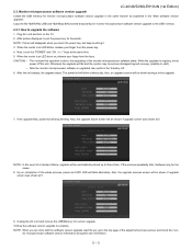
...moment this operation is ongoing, never power off the unit. After the unit startup, the upgrade starts. If the upgrade fails, power led will blink continuously. LE810UN NOTE: In the event of the monitor microprocessor software starts. LE810UN 9. Next, touch the "POWER" and...adjustment process screen and check the mon- itor microprocessor software version information and panel size information. 5 - 3 LE810UN 7. LC-40/46/52/60LE810UN (1st Edition) 2.3. When the center icon LED blinks, release your finger form the keys. Monitor microprocessor software version upgrade ...
...moment this operation is ongoing, never power off the unit. After the unit startup, the upgrade starts. If the upgrade fails, power led will blink continuously. LE810UN NOTE: In the event of the monitor microprocessor software starts. LE810UN 9. Next, touch the "POWER" and...adjustment process screen and check the mon- itor microprocessor software version information and panel size information. 5 - 3 LE810UN 7. LC-40/46/52/60LE810UN (1st Edition) 2.3. When the center icon LED blinks, release your finger form the keys. Monitor microprocessor software version upgrade ...
Service Manual
Page 38
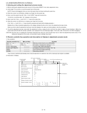
... was turned off with "VOL (-)" and "INPUT" keys at the same time. 6) When the center icon LED turns on , touch the power key for 5seconds. LC-40/46/52/60LE810UN (1st Edition) 3. In this mode, unrecoverable system damage may result. 4. Entering and exiting the adjustment process ... state TV is available. 2) Description of display (1) Current page/ Total pages (2) Current selected input (3) Current color system (4) Destination (5) LCD Panel size/Speaker type 1/24 INPUT5 AUTO MAIN Version 1.09 (U 2009/07/07 1A) BOOT Version Monitor/Monitor BOOT Version LCD Con Version HLNI 100...
... was turned off with "VOL (-)" and "INPUT" keys at the same time. 6) When the center icon LED turns on , touch the power key for 5seconds. LC-40/46/52/60LE810UN (1st Edition) 3. In this mode, unrecoverable system damage may result. 4. Entering and exiting the adjustment process ... state TV is available. 2) Description of display (1) Current page/ Total pages (2) Current selected input (3) Current color system (4) Destination (5) LCD Panel size/Speaker type 1/24 INPUT5 AUTO MAIN Version 1.09 (U 2009/07/07 1A) BOOT Version Monitor/Monitor BOOT Version LCD Con Version HLNI 100...

Service Manual
Page 39
... 6 7 8 9 10 11 12 13 1 2 3 4 5 6 7 8 9 10 11 12 13 1 2 3 4 5 6 7 8 9 1 2 3 4 5 6 7 1 2 3 4 5 6 7 1 2 3 4 5 6 7 Item MAIN Version BOOT Version Monitor/Monitor BOOT Version LCD CON Version / LED CON Version Netflix ESN FRC-N Auto Script Version TCON Master/Slave Serial Version TOUCH SENSOR UCON VERSION TEMPERATURE LAMP ERROR MONITOR ERR CAUSE NORMAL STANDBY... Main software version Monitor and monitor boot software version LCD controller software version Audio data checksum Panel temperature Number of adjustment process mode menu The character string in brackets [ ] will appear as a ...
... 6 7 8 9 10 11 12 13 1 2 3 4 5 6 7 8 9 10 11 12 13 1 2 3 4 5 6 7 8 9 1 2 3 4 5 6 7 1 2 3 4 5 6 7 1 2 3 4 5 6 7 Item MAIN Version BOOT Version Monitor/Monitor BOOT Version LCD CON Version / LED CON Version Netflix ESN FRC-N Auto Script Version TCON Master/Slave Serial Version TOUCH SENSOR UCON VERSION TEMPERATURE LAMP ERROR MONITOR ERR CAUSE NORMAL STANDBY... Main software version Monitor and monitor boot software version LCD controller software version Audio data checksum Panel temperature Number of adjustment process mode menu The character string in brackets [ ] will appear as a ...
Service Manual
Page 68
...Since only the center icon LED can be used ) 1. LC-40/46/52/60LE810UN (1st Edition) Trouble Shooting Panel Module When C-S FPC(2 pieces) is replaced, does screen display normally? NO When C-PWB is replaced, does screen display normally? YES Replace C-S FPC(2 pieces). LED flashing method Error flashing ...- 14 YES Replace C-PWB. (Adjust "VCOM ADJ" after replace C-PWB) NO Replace Panel HIRAKI. (Adjust "VCOM ADJ" after replace Panel HIRAKI) [2] LED flashing specification at the time of an error (Center icon LED used , slow flashing and fast flashing are combined. • Refer to Table 1. &#...
...Since only the center icon LED can be used ) 1. LC-40/46/52/60LE810UN (1st Edition) Trouble Shooting Panel Module When C-S FPC(2 pieces) is replaced, does screen display normally? NO When C-PWB is replaced, does screen display normally? YES Replace C-S FPC(2 pieces). LED flashing method Error flashing ...- 14 YES Replace C-PWB. (Adjust "VCOM ADJ" after replace C-PWB) NO Replace Panel HIRAKI. (Adjust "VCOM ADJ" after replace Panel HIRAKI) [2] LED flashing specification at the time of an error (Center icon LED used , slow flashing and fast flashing are combined. • Refer to Table 1. &#...
Service Manual
Page 70
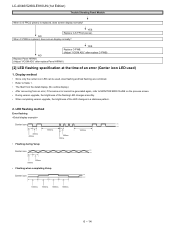
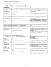
...ERR_PNL(40pin): Hi failure. DET_D3V3(36pin) failure (L). If error is detected during start -up or operation, the power is on the panel power and receiving command; Detection is started after 8 consecutive detections at the time of an error 100ms 400ms 1.6sec 1) Slow flashing Error...3V failure Flashes fast 3 times PANEL_POW Panel 12V failure Flashes fast 5 times H: On L: Off H: On L: Off H: On L: Off H: On L: Off Note Pins are monitor microcomputer pins unless otherwise specified. LC-40/46/52/60LE810UN (1st Edition) LED flashing timing chart at 64msec intervals (detected...
...ERR_PNL(40pin): Hi failure. DET_D3V3(36pin) failure (L). If error is detected during start -up or operation, the power is on the panel power and receiving command; Detection is started after 8 consecutive detections at the time of an error 100ms 400ms 1.6sec 1) Slow flashing Error...3V failure Flashes fast 3 times PANEL_POW Panel 12V failure Flashes fast 5 times H: On L: Off H: On L: Off H: On L: Off H: On L: Off Note Pins are monitor microcomputer pins unless otherwise specified. LC-40/46/52/60LE810UN (1st Edition) LED flashing timing chart at 64msec intervals (detected...
Service Manual
Page 71
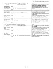
...in red in a row, error standby is not received. (Request for 15 seconds or more in the lower right screen). If the panel temperature is 60°C or more for the monitor model No. Initial communication from the main CPU, etc. → Main CPU operation ...5) Other failure details (Flashes slowly 4 times and flashes fast) Error type Center icon LED operation Monitor temperature failure Flashes fast once H: On L: Off Main failure H: On Flashes fast 3 times L: Off LC-40/46/52/60LE810UN (1st Edition) Note Basically, debug print logs are analyzed or communication logs are displayed ...
...in red in a row, error standby is not received. (Request for 15 seconds or more in the lower right screen). If the panel temperature is 60°C or more for the monitor model No. Initial communication from the main CPU, etc. → Main CPU operation ...5) Other failure details (Flashes slowly 4 times and flashes fast) Error type Center icon LED operation Monitor temperature failure Flashes fast once H: On L: Off Main failure H: On Flashes fast 3 times L: Off LC-40/46/52/60LE810UN (1st Edition) Note Basically, debug print logs are analyzed or communication logs are displayed ...

Service Manual
Page 79
LC-40/46/52/60LE810UN (1st Edition) [3] CABINET AND MECHANICAL PARTS (LC-40LE810UN) 1 J a 31 30 k K e ICON 1-2 Unit d TOUCH b R/C, SENSOR LED Unit Unit 31 f POWER/LED g 27 DRIVE m Unit n 17 F 23 42 3 27 j 20 MAIN Unit k 17 24 f g B F 12 H 27 27 18 E 40 13 9... 27 27 9 27 19 7 14 20 27 41 27 11 40 32 27 h G 15 j 32 E 40" LCD PANEL...
LC-40/46/52/60LE810UN (1st Edition) [3] CABINET AND MECHANICAL PARTS (LC-40LE810UN) 1 J a 31 30 k K e ICON 1-2 Unit d TOUCH b R/C, SENSOR LED Unit Unit 31 f POWER/LED g 27 DRIVE m Unit n 17 F 23 42 3 27 j 20 MAIN Unit k 17 24 f g B F 12 H 27 27 18 E 40 13 9... 27 27 9 27 19 7 14 20 27 41 27 11 40 32 27 h G 15 j 32 E 40" LCD PANEL...

Service Manual
Page 81
LC-40/46/52/60LE810UN (1st Edition) [4] CABINET AND MECHANICAL PARTS (LC-46LE810UN) 1 J 8 a 26 33 L f POWER/LED g DRIVE 26 34 Unit j 22 L k F 1-2 d ICON e Unit TOUCH b LERD/CU,nitSEUNnSitOR 28 48 3 j 34 25 MAIN h Unit 29 j 23 22 27 E 34 12 H 36 34 ... 34 11 20 38 14 34 34 34 13 34 47 G 16 20 34 37 10 h 15 j 41 K 2 2-2 E 2-8 2-1 21 17 6 34 21 34 46" LCD PANEL Module C 34 C 2-9 42 B 2-5 2-7 A 2-6 17 21 20 49 18 51 50 51-3 A 2-11 2-4 2-11 2-10 24 25 k a 31 32 h e d b 30 35 h G 19 46 44 43 2-3 46...
LC-40/46/52/60LE810UN (1st Edition) [4] CABINET AND MECHANICAL PARTS (LC-46LE810UN) 1 J 8 a 26 33 L f POWER/LED g DRIVE 26 34 Unit j 22 L k F 1-2 d ICON e Unit TOUCH b LERD/CU,nitSEUNnSitOR 28 48 3 j 34 25 MAIN h Unit 29 j 23 22 27 E 34 12 H 36 34 ... 34 11 20 38 14 34 34 34 13 34 47 G 16 20 34 37 10 h 15 j 41 K 2 2-2 E 2-8 2-1 21 17 6 34 21 34 46" LCD PANEL Module C 34 C 2-9 42 B 2-5 2-7 A 2-6 17 21 20 49 18 51 50 51-3 A 2-11 2-4 2-11 2-10 24 25 k a 31 32 h e d b 30 35 h G 19 46 44 43 2-3 46...

Service Manual
Page 83
LC-40/46/52/60LE810UN (1st Edition) [5] CABINET AND MECHANICAL PARTS (LC-52LE810UN) 1 J K e 1-2 d ICON Unit TOUCH b SENSOR R/C, Unit LED Unit 37 14 37 H 34 22 23 37 7 37 22 23 f 44 g B 35 22 34 37 37 13 D 23 37 37 F 44 G 36 16 37 ...24 15 h j 19 17 37 22 35 37 12 K E 44 2-1 52" LCD PANEL...
LC-40/46/52/60LE810UN (1st Edition) [5] CABINET AND MECHANICAL PARTS (LC-52LE810UN) 1 J K e 1-2 d ICON Unit TOUCH b SENSOR R/C, Unit LED Unit 37 14 37 H 34 22 23 37 7 37 22 23 f 44 g B 35 22 34 37 37 13 D 23 37 37 F 44 G 36 16 37 ...24 15 h j 19 17 37 22 35 37 12 K E 44 2-1 52" LCD PANEL...

Service Manual
Page 85
... Edition) [6] CABINET AND MECHANICAL PARTS (LC-60LE810UN) a 1 21 37 K f 40 g B h j E 19 C 18 46 A 17 J K e ICON 1-2 d Unit TOUCH b R/C, SENSOR Unit LED Unit 38 9 38 H 10 55 26 38 53 7 56 55 F G 10 40 27 22 56 L 38 8 38 38 38 10 23 21 51 MAIN... 38 Unit k 35 28 29 E 30 m 32 a n 34 36 h 51 e d b 39 39 24 24 f POWER/LED g DRIVE m 38 Unit 28 n F 31 3 j 54 33 47 kG 25 40 60" LCD PANEL Module 38 43 2 2-2 2-1 B 2-7 2-9 2-8 2-6 2-10 6 2-5 2-8 2-4 2-8 41 41 42 41 44 2-3 5 4 41 A 45 20 49 13 ...
... Edition) [6] CABINET AND MECHANICAL PARTS (LC-60LE810UN) a 1 21 37 K f 40 g B h j E 19 C 18 46 A 17 J K e ICON 1-2 d Unit TOUCH b R/C, SENSOR Unit LED Unit 38 9 38 H 10 55 26 38 53 7 56 55 F G 10 40 27 22 56 L 38 8 38 38 38 10 23 21 51 MAIN... 38 Unit k 35 28 29 E 30 m 32 a n 34 36 h 51 e d b 39 39 24 24 f POWER/LED g DRIVE m 38 Unit 28 n F 31 3 j 54 33 47 kG 25 40 60" LCD PANEL Module 38 43 2 2-2 2-1 B 2-7 2-9 2-8 2-6 2-10 6 2-5 2-8 2-4 2-8 41 41 42 41 44 2-3 5 4 41 A 45 20 49 13 ...


