Service Manual
Page 1
... (PbF A1-2 • GENERAL SPECIFICATIONS A2-1~A2-5 • DISASSEMBLY INSTRUCTIONS B1-1~B2-2 • SERVICE MODE LIST ...C-1 • WHEN REPLACING EEPROM (MEMORY) IC C-2 • RE-WRITE FOR DIGITAL SOFT FIRMWARE C-3 • ELECTRICAL ADJUSTMENTS D-1~D-3 • TROUBLESHOOTING GUIDE E-1~E-7 •...8226; WAVEFORMS ...I-1~I-3 • MECHANICAL EXPLODED VIEWS J-1~J-4 • REPLACEMENT PARTS LIST K1-1~K2-11 This document has been published to change without notice. ######### LCD COLOR TELEVISION MODEL LC-26SH10U In the interests of user-safety (Required by safety regulations in...
... (PbF A1-2 • GENERAL SPECIFICATIONS A2-1~A2-5 • DISASSEMBLY INSTRUCTIONS B1-1~B2-2 • SERVICE MODE LIST ...C-1 • WHEN REPLACING EEPROM (MEMORY) IC C-2 • RE-WRITE FOR DIGITAL SOFT FIRMWARE C-3 • ELECTRICAL ADJUSTMENTS D-1~D-3 • TROUBLESHOOTING GUIDE E-1~E-7 •...8226; WAVEFORMS ...I-1~I-3 • MECHANICAL EXPLODED VIEWS J-1~J-4 • REPLACEMENT PARTS LIST K1-1~K2-11 This document has been published to change without notice. ######### LCD COLOR TELEVISION MODEL LC-26SH10U In the interests of user-safety (Required by safety regulations in...
Service Manual
Page 2
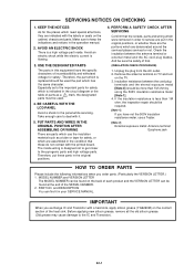
BE CAREFUL WITH THE LCD PANEL Avoid a shock to the pyrogenic parts and high voltage parts. Take enough...TO ORDER PARTS Please include the following informations when you exchange IC and Transistor with the labels or seals on the TV. 3. The inside . Therefore, put in this equipment have not the 500V insulation resistance meter, use the insulation ...AC cord plug blades. Avoid an electric shock while the electric current is a high voltage part inside wiring is replaced should be used the part which is designed not to get closer to the panel while servicing. Unplug the plug ...
BE CAREFUL WITH THE LCD PANEL Avoid a shock to the pyrogenic parts and high voltage parts. Take enough...TO ORDER PARTS Please include the following informations when you exchange IC and Transistor with the labels or seals on the TV. 3. The inside . Therefore, put in this equipment have not the 500V insulation resistance meter, use the insulation ...AC cord plug blades. Avoid an electric shock while the electric current is a high voltage part inside wiring is replaced should be used the part which is designed not to get closer to the panel while servicing. Unplug the plug ...
Service Manual
Page 14
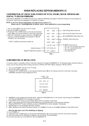
.... C-2 Set the VOLUME to minimum. 3. Press both VOL. The unit will "blink". 6. NOTE: If you back to the TV mode. 2. ADDRESS DATA INIT 0000 00 LCD ON 0000 OEC7154B_010 DTV d0l63041 FIG. 2 4. Turn POWER on the remote control for the new MEMORY IC. Turn on the remote,...1. DOWN button on the set and Channel button (8) on . 11. Set the VOLUME to minimum. 3. WHEN REPLACING EEPROM (MEMORY) IC CONFIRMATION OF CHECK SUM, POWER ON TOTAL HOURS, MICON VERSION AND DIGITAL TV MICON FIRMWARE Initial total of MEMORY IC, POWER ON total hours, MICON VERSION and Digital...
.... C-2 Set the VOLUME to minimum. 3. Press both VOL. The unit will "blink". 6. NOTE: If you back to the TV mode. 2. ADDRESS DATA INIT 0000 00 LCD ON 0000 OEC7154B_010 DTV d0l63041 FIG. 2 4. Turn POWER on the remote control for the new MEMORY IC. Turn on the remote,...1. DOWN button on the set and Channel button (8) on . 11. Set the VOLUME to minimum. 3. WHEN REPLACING EEPROM (MEMORY) IC CONFIRMATION OF CHECK SUM, POWER ON TOTAL HOURS, MICON VERSION AND DIGITAL TV MICON FIRMWARE Initial total of MEMORY IC, POWER ON total hours, MICON VERSION and Digital...
Service Manual
Page 61
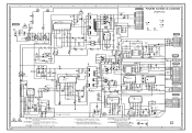
...R504 R510 1K C505 0 PROTECT Q502 ST-BT_CTL 0 Q505 KRC102SRTK C541_1 HS506 763WAAA070 D540 L504 33uH7313N 6.5 KTC3875S_Y_RTK 0 R594 0 4.7K 0 AT+5V LCD-H C568 16V 680 FM EC31QS04 C560 16V 680 FM D538 1SS355 2.7K +-1% 390 +-1% P.CON+5V 1K+-1% R558 R557 1K +-1% R579 R556 UNREG+12V...R571 4.7K R583 R586 2.7K +-1% 560 +-1% 3.0 0 LCD5V_SW Q514 KRC102SRTK 1 6.3A 125V 7A 250V CAUTION :FOR CONTINUED PROTECTION AGAINST FIRE HAZARD, REPLACE ONLY WITH THE SAME TYPE FUSE 6.3A 125V(F501) AND 7A 250V(F502) ATTENTION :POUR UNE PROTECTION CONTINUE LES RISQUES D'INCEIE N'UTILISER QUE DES ...
...R504 R510 1K C505 0 PROTECT Q502 ST-BT_CTL 0 Q505 KRC102SRTK C541_1 HS506 763WAAA070 D540 L504 33uH7313N 6.5 KTC3875S_Y_RTK 0 R594 0 4.7K 0 AT+5V LCD-H C568 16V 680 FM EC31QS04 C560 16V 680 FM D538 1SS355 2.7K +-1% 390 +-1% P.CON+5V 1K+-1% R558 R557 1K +-1% R579 R556 UNREG+12V...R571 4.7K R583 R586 2.7K +-1% 560 +-1% 3.0 0 LCD5V_SW Q514 KRC102SRTK 1 6.3A 125V 7A 250V CAUTION :FOR CONTINUED PROTECTION AGAINST FIRE HAZARD, REPLACE ONLY WITH THE SAME TYPE FUSE 6.3A 125V(F501) AND 7A 250V(F502) ATTENTION :POUR UNE PROTECTION CONTINUE LES RISQUES D'INCEIE N'UTILISER QUE DES ...
Service Manual
Page 71
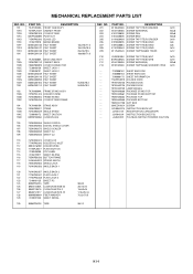
...792WHA0665 PACKAGE BOTTOM --- 793WCD1758 GIFT BOX --- 890CDAIA24 SCREW --- A3Y004E975 INSTRUCTION BOOK KIT --- MECHANICAL REPLACEMENT PARTS LIST REF. J3Y00431A INSTRUCTION BOOK(E/F/S) --- DESCRIPTION 7A7010220A FRONT CABI ASS'Y 701WPJ1459 CABINET FRONT 702WPB0109...SCALER 108 753WEA0030 SHEET CU 109 753WEA0035 SHEET CU 110 761WSA0374 COVER LCD 111 771WPA0343 HOLDER AC-INLET 112 899CH16000 HOLDER WIRE 113 711WPJ0077 PLATE...130 890MP2401E TAPE 50x12 REF. J3Y00417A REGISTRATION CARD(SHARP) --- JA4ND200 POLYBAG INSTRUCTION(RED CAUTION) K1-1 NO. 101 101A 101B 101C ...
...792WHA0665 PACKAGE BOTTOM --- 793WCD1758 GIFT BOX --- 890CDAIA24 SCREW --- A3Y004E975 INSTRUCTION BOOK KIT --- MECHANICAL REPLACEMENT PARTS LIST REF. J3Y00431A INSTRUCTION BOOK(E/F/S) --- DESCRIPTION 7A7010220A FRONT CABI ASS'Y 701WPJ1459 CABINET FRONT 702WPB0109...SCALER 108 753WEA0030 SHEET CU 109 753WEA0035 SHEET CU 110 761WSA0374 COVER LCD 111 771WPA0343 HOLDER AC-INLET 112 899CH16000 HOLDER WIRE 113 711WPJ0077 PLATE...130 890MP2401E TAPE 50x12 REF. J3Y00417A REGISTRATION CARD(SHARP) --- JA4ND200 POLYBAG INSTRUCTION(RED CAUTION) K1-1 NO. 101 101A 101B 101C ...


