Service Manual
Page 1
... FREE SOLDER (PbF A1-2 • GENERAL SPECIFICATIONS A2-1~A2-5 • DISASSEMBLY INSTRUCTIONS B1-1~B2-2 • SERVICE MODE LIST ...C-1 • WHEN REPLACING EEPROM (MEMORY) IC C-2 • RE-WRITE FOR DIGITAL SOFT FIRMWARE C-3 • ELECTRICAL ADJUSTMENTS D-1~D-3 • TROUBLESHOOTING GUIDE E-1~E-7 • BLOCK DIAGRAM ...F-1~F-10 • PRINTED CIRCUIT BOARDS G-1~G-14 • SCHEMATIC DIAGRAMS ...H-1~H-52 • WAVEFORMS ...I-1~I-3 • MECHANICAL EXPLODED VIEWS J-1~J-4 • REPLACEMENT PARTS LIST K1-1~K2-11 This document has been published to change...
... FREE SOLDER (PbF A1-2 • GENERAL SPECIFICATIONS A2-1~A2-5 • DISASSEMBLY INSTRUCTIONS B1-1~B2-2 • SERVICE MODE LIST ...C-1 • WHEN REPLACING EEPROM (MEMORY) IC C-2 • RE-WRITE FOR DIGITAL SOFT FIRMWARE C-3 • ELECTRICAL ADJUSTMENTS D-1~D-3 • TROUBLESHOOTING GUIDE E-1~E-7 • BLOCK DIAGRAM ...F-1~F-10 • PRINTED CIRCUIT BOARDS G-1~G-14 • SCHEMATIC DIAGRAMS ...H-1~H-52 • WAVEFORMS ...I-1~I-3 • MECHANICAL EXPLODED VIEWS J-1~J-4 • REPLACEMENT PARTS LIST K1-1~K2-11 This document has been published to change...
Service Manual
Page 2
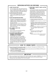
... ohm, the inspection repair should be used . 4. PART NO. Make sure to the important parts for safety. BE CAREFUL WITH THE LCD PANEL Avoid a shock to the IC and Transistor). Insulation resistance between the antenna terminal or external metal and the AC cord plug blades. Especially as a mark, the designated parts must be used the part which is indicated in the operation manual. 2. IMPORTANT When...
... ohm, the inspection repair should be used . 4. PART NO. Make sure to the important parts for safety. BE CAREFUL WITH THE LCD PANEL Avoid a shock to the IC and Transistor). Insulation resistance between the antenna terminal or external metal and the AC cord plug blades. Especially as a mark, the designated parts must be used the part which is indicated in the operation manual. 2. IMPORTANT When...
Service Manual
Page 4
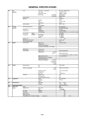
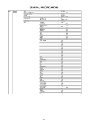
... SPECIFICATIONS G-1 TV System G-2 Tuning System G-3 Signal LCD Color System Speaker Sound Output Broadcasting System Tuner and Receive CH Intermediate Frequency Digital Analog Preset CH Stereo/Dual TV Sound Tuner Sound Muting Video Signal LCD Size / Visual Size LCD Type Number of Pixels View Range Left/Right Up/Down Position Size Impedance Max 10%(Typical) Analog Digital System Destination CH Coverage Picture(FP) Sound(FS) FP-FS Input Level Output Level S/N Ratio (Weighted) Horizontal Resolution at DVD Mode RGB Signal Audio Signal Output Level Input Level Output Level at DVD...
... SPECIFICATIONS G-1 TV System G-2 Tuning System G-3 Signal LCD Color System Speaker Sound Output Broadcasting System Tuner and Receive CH Intermediate Frequency Digital Analog Preset CH Stereo/Dual TV Sound Tuner Sound Muting Video Signal LCD Size / Visual Size LCD Type Number of Pixels View Range Left/Right Up/Down Position Size Impedance Max 10%(Typical) Analog Digital System Destination CH Coverage Picture(FP) Sound(FS) FP-FS Input Level Output Level S/N Ratio (Weighted) Horizontal Resolution at DVD Mode RGB Signal Audio Signal Output Level Input Level Output Level at DVD...
Service Manual
Page 5
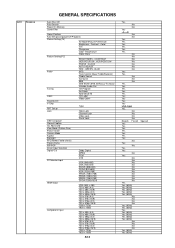
ENT INPUT FLASH BACK VOL+ VOLCH+ CHSURROUND MUTE FREEZE MENU LEFT ENTER RIGHT UP DOWN EXIT RETURN FAVORITE A FAVORITE B FAVORITE C FAVORITE D FAVORITE SLEEP AUDIO AV MODE CC RC-MQ No SHARP SHARP 10000 / 10001 3V UM-3 x 2 pcs 40 Keys Yes No No Yes No No No ...Yes Yes Yes Yes Yes Yes Yes Yes Yes No Yes Yes Yes Yes A2-2 G-9 Remote Control GENERAL SPECIFICATIONS Unit Glow in Dark Remocon Remocon Format Format Custom Code Power Source Total Keys Keys Voltage(D.C) UM size x pcs POWER FUNCTION Source POWER DISPLAY LIGHT SEARCH+ SEARCHPLAY REC STOP PAUSE SKIP+ SKIPVIEW MODE 1 2 3 4 5 6 7 8 9 0 .
ENT INPUT FLASH BACK VOL+ VOLCH+ CHSURROUND MUTE FREEZE MENU LEFT ENTER RIGHT UP DOWN EXIT RETURN FAVORITE A FAVORITE B FAVORITE C FAVORITE D FAVORITE SLEEP AUDIO AV MODE CC RC-MQ No SHARP SHARP 10000 / 10001 3V UM-3 x 2 pcs 40 Keys Yes No No Yes No No No ...Yes Yes Yes Yes Yes Yes Yes Yes Yes No Yes Yes Yes Yes A2-2 G-9 Remote Control GENERAL SPECIFICATIONS Unit Glow in Dark Remocon Remocon Format Format Custom Code Power Source Total Keys Keys Voltage(D.C) UM size x pcs POWER FUNCTION Source POWER DISPLAY LIGHT SEARCH+ SEARCHPLAY REC STOP PAUSE SKIP+ SKIPVIEW MODE 1 2 3 4 5 6 7 8 9 0 .
Service Manual
Page 6
... AUTO ADJUST RED , GREEN , BLUE Audio MTS Tone Control (Bass/Treble/Balance) Stable Sound Surround BBE SRS WOW (SRS 3D/Focus/Tru Bass) Valiable Audio Out Tuning CH Program Air/Cable ADD/DELETE Label CH Label Video Label Favorite CH V-Chip Type RRT Setup Lock Hotel Lock Channel Lock Video Lock Panel Lock OSD Language Closed Caption CC Advanced View Mode (Picture Size) Picture Scroll Cinema Mode Aspect Backlight PFC(Power Factor circuit) Freeze frame PIP/POP Direct Input Selection Digital Out Dolby Digital...
... AUTO ADJUST RED , GREEN , BLUE Audio MTS Tone Control (Bass/Treble/Balance) Stable Sound Surround BBE SRS WOW (SRS 3D/Focus/Tru Bass) Valiable Audio Out Tuning CH Program Air/Cable ADD/DELETE Label CH Label Video Label Favorite CH V-Chip Type RRT Setup Lock Hotel Lock Channel Lock Video Lock Panel Lock OSD Language Closed Caption CC Advanced View Mode (Picture Size) Picture Scroll Cinema Mode Aspect Backlight PFC(Power Factor circuit) Freeze frame PIP/POP Direct Input Selection Digital Out Dolby Digital...
Service Manual
Page 7
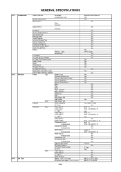
... Adapter) AC Cord (Flat Polarity Plugs) Cable Cramp Stand Stand Screw Hexagon Wrench AV Cord (2Pin-1Pin) Registration Card (NDL Card) 300 to 75ohm Antenna Adapter Switch Top Indicator Terminals Rear Rear Side Language w/Guarantee Card Poles Terminal Terminal UM size x pcs OEM Brand Power (Tact) Channel Up/Menu Up Channel Down/Menu Down Volume Up/Menu > Volume Down/Menu < Menu Play Eject Skip+, Search+ Skip-, SearchStill/Pause Stop Main Power SW Input Select Main Power SW Power/Stand-By On Timer Video Input 1 Audio Input...
... Adapter) AC Cord (Flat Polarity Plugs) Cable Cramp Stand Stand Screw Hexagon Wrench AV Cord (2Pin-1Pin) Registration Card (NDL Card) 300 to 75ohm Antenna Adapter Switch Top Indicator Terminals Rear Rear Side Language w/Guarantee Card Poles Terminal Terminal UM size x pcs OEM Brand Power (Tact) Channel Up/Menu Up Channel Down/Menu Down Volume Up/Menu > Volume Down/Menu < Menu Play Eject Skip+, Search+ Skip-, SearchStill/Pause Stop Main Power SW Input Select Main Power SW Power/Stand-By On Timer Video Input 1 Audio Input...
Service Manual
Page 8
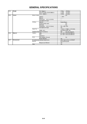
... Weight G-15 Carton G-16 Material G-17 Environment GENERAL SPECIFICATIONS Net (Approx.) Net w/o Handle, Stand (Approx.) Gross (Approx.) Master Carton Content Material Dimensions W x D x H(mm) Description of Origin Gift Box Material W/Color Photo Label W/Handle Dimensions W x D x H(mm) Description of SHARP Phase3(Phase3A) Yes Yes A2-5 No Yes Green procurement of Origin Drop Test Height (cm) Container Stuffing (40' container) Cabinet Front Rear...
... Weight G-15 Carton G-16 Material G-17 Environment GENERAL SPECIFICATIONS Net (Approx.) Net w/o Handle, Stand (Approx.) Gross (Approx.) Master Carton Content Material Dimensions W x D x H(mm) Description of Origin Gift Box Material W/Color Photo Label W/Handle Dimensions W x D x H(mm) Description of SHARP Phase3(Phase3A) Yes Yes A2-5 No Yes Green procurement of Origin Drop Test Height (cm) Container Stuffing (40' container) Cabinet Front Rear...
Service Manual
Page 11
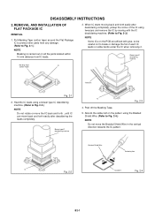
...lands under the IC when removing it. DISASSEMBLY INSTRUCTIONS 2. Peel off the Masking Tape. 5. Put Masking Tape (cotton tape) around the Flat Package IC to protect other parts from IC leads. 3. Blower type IC desoldering machine IC Fig. 2-3 4. Absorb the solder left on the pattern using tweezers and remove the IC by moving with..., so be careful not to Fig. 2-1.) NOTE Masking is carried out on all the parts located within 10 mm distance from any damage. (Refer to break or damage the foil of the IC using the Braided Shield Wire. (Refer to Fig. 2-2.) NOTE Do not rotate or move the...
...lands under the IC when removing it. DISASSEMBLY INSTRUCTIONS 2. Peel off the Masking Tape. 5. Put Masking Tape (cotton tape) around the Flat Package IC to protect other parts from IC leads. 3. Blower type IC desoldering machine IC Fig. 2-3 4. Absorb the solder left on the pattern using tweezers and remove the IC by moving with..., so be careful not to Fig. 2-1.) NOTE Masking is carried out on all the parts located within 10 mm distance from any damage. (Refer to break or damage the foil of the IC using the Braided Shield Wire. (Refer to Fig. 2-2.) NOTE Do not rotate or move the...
Service Manual
Page 12
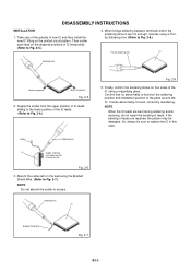
...using a Thintip Soldering Iron. (Refer to replace the IC in this case. Braided Shield Wire Fig. 2-7 B2-2 Confirm that no abnormality is found on the printed circuit pattern. If the bending of the parts around the IC. Supply the solder from upper position to the lower position of new IC and then install... are bent during soldering and/or repairing, do not repair the bending of the IC using a magnifying glass. So, always be damaged. DISASSEMBLY INSTRUCTIONS INSTALLATION 1. NOTE When the IC leads are not enough, resolder using the Braided Shield Wire. (Refer to...
...using a Thintip Soldering Iron. (Refer to replace the IC in this case. Braided Shield Wire Fig. 2-7 B2-2 Confirm that no abnormality is found on the printed circuit pattern. If the bending of the parts around the IC. Supply the solder from upper position to the lower position of new IC and then install... are bent during soldering and/or repairing, do not repair the bending of the IC using a magnifying glass. So, always be damaged. DISASSEMBLY INSTRUCTIONS INSTALLATION 1. NOTE When the IC leads are not enough, resolder using the Braided Shield Wire. (Refer to...
Service Manual
Page 13
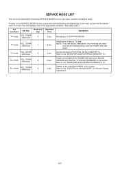
... the remote control for more than the standard time in the appropriate condition. (See below chart.) Set Condition Set Key Remocon Key TV mode VOL. Initialization of the SUM DATA, POWER ON total hours, MICON VERSION and DIGITAL TV MICON FIRMWARE on the screen. SERVICE MODE LIST This unit is provided with the following SERVICE MODES so you set factory initialization, the memories are reset such as the channel setting, and the POWER...
... the remote control for more than the standard time in the appropriate condition. (See below chart.) Set Condition Set Key Remocon Key TV mode VOL. Initialization of the SUM DATA, POWER ON total hours, MICON VERSION and DIGITAL TV MICON FIRMWARE on the screen. SERVICE MODE LIST This unit is provided with the following SERVICE MODES so you set factory initialization, the memories are reset such as the channel setting, and the POWER...
Service Manual
Page 14
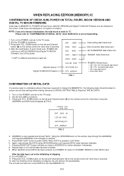
... Digital TV MICON Firmware, turn off the power. *1 DVP1 is reset to "0". ADDRESS DATA INIT 0000 00 LCD ON 0000 OEC7154B_010 DTV d0l63041 FIG. 2 4. Repeat steps 4 to finish DATA input. C-2 Turn on . 11. After the confirmation of each set and Channel button (8) on the remote control for more than 2 seconds. 4. POWER ON total hours. = (16 x 16 x 16 x thousands digit value) + (16 x 16 x hundreds digit value) + (16 x tens digit...
... Digital TV MICON Firmware, turn off the power. *1 DVP1 is reset to "0". ADDRESS DATA INIT 0000 00 LCD ON 0000 OEC7154B_010 DTV d0l63041 FIG. 2 4. Repeat steps 4 to finish DATA input. C-2 Turn on . 11. After the confirmation of each set and Channel button (8) on the remote control for more than 2 seconds. 4. POWER ON total hours. = (16 x 16 x 16 x thousands digit value) + (16 x 16 x hundreds digit value) + (16 x tens digit...
Service Manual
Page 15
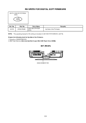
Prepare the following tools for Up-Date of the Firmware. 1 Computer of the Firmware NOTE: The operating manual for Re-writing is included in USA HD DTV ROM DISC (JG176). JG176 Part No. APJG176095 Parts Name USA HD DTV ROM DISC Remarks Up-Date of WINDOWS2000 2 USB Flash Memory (Use only SanDisk Cruzer Mini USB Flash Drive 256Mb) SET (REAR) USB CONNECTOR C-3 RE-WRITE FOR DIGITAL SOFT FIRMWARE JG176 USA HD DTV ROM DISC Ref. No.
Prepare the following tools for Up-Date of the Firmware. 1 Computer of the Firmware NOTE: The operating manual for Re-writing is included in USA HD DTV ROM DISC (JG176). JG176 Part No. APJG176095 Parts Name USA HD DTV ROM DISC Remarks Up-Date of WINDOWS2000 2 USB Flash Memory (Use only SanDisk Cruzer Mini USB Flash Drive 256Mb) SET (REAR) USB CONNECTOR C-3 RE-WRITE FOR DIGITAL SOFT FIRMWARE JG176 USA HD DTV ROM DISC Ref. No.
Service Manual
Page 16
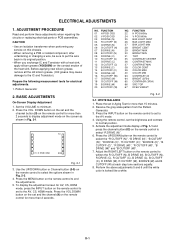
..., HDMI mode, press the INPUT button on the remote control to the AV, CS, HDMI mode. Before applying new silicon grease, remove all the old silicon grease. (Old grease may cause damage to minimum. 2. DOWN button on the set to set and the channel button (9) on the remote control for more than 15 minutes. 2. ADJUSTMENT PROCEDURE Read and perform these adjustments when repairing the circuits or replacing electrical parts or PCB assemblies. Set...
..., HDMI mode, press the INPUT button on the remote control to the AV, CS, HDMI mode. Before applying new silicon grease, remove all the old silicon grease. (Old grease may cause damage to minimum. 2. DOWN button on the set to set and the channel button (9) on the remote control for more than 15 minutes. 2. ADJUSTMENT PROCEDURE Read and perform these adjustments when repairing the circuits or replacing electrical parts or PCB assemblies. Set...
Service Manual
Page 23
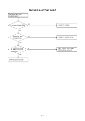
CONNECT DIGITAL PCB. YES IS THERE VOLTAGE NO AT PINS 1 AND 2 OF CD3806 5V ? CONNECT CD3806. E-5 YES CHANGE DIGITAL PCB. YES IS DIGITAL PCB NO CONNECTED ? CHECK Q512, IC509 AND PERIPHERAL CIRCUIT. TROUBLESHOOTING GUIDE NO IS CD3806 CONNECTED ? THE STOP PICTURE "PLEASE WAIT".
CONNECT DIGITAL PCB. YES IS THERE VOLTAGE NO AT PINS 1 AND 2 OF CD3806 5V ? CONNECT CD3806. E-5 YES CHANGE DIGITAL PCB. YES IS DIGITAL PCB NO CONNECTED ? CHECK Q512, IC509 AND PERIPHERAL CIRCUIT. TROUBLESHOOTING GUIDE NO IS CD3806 CONNECTED ? THE STOP PICTURE "PLEASE WAIT".
Service Manual
Page 39
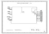
...-H 7 RLY_ON/LCD-H LCD-H/PDP_RLY 6 NC S_DET 5 SW_YUV1/2 PSU_5VD/DSR/LIGHT_CTL NC 4 SW_YUV1/2 3 NC 2 LIGHT CTL/PSU_5VD1 CD4204 2H0U1102 3 2 1 H-3 NOTE: THIS SCHEMATIC DIAGRAM IS THE LATEST AT THE TIME OF PRINTING AND SUBJECT TO CHANGE WITHOUT NOTICE NOTE:THE DC VOLTAGE AT EACH PART WAS MEASURED WITH THE DIGITAL TESTER WHEN THE COLOR BROADCAST WAS RECEIVED IN GOOD CONDITION AND PICTURE IS NORMAL.
...-H 7 RLY_ON/LCD-H LCD-H/PDP_RLY 6 NC S_DET 5 SW_YUV1/2 PSU_5VD/DSR/LIGHT_CTL NC 4 SW_YUV1/2 3 NC 2 LIGHT CTL/PSU_5VD1 CD4204 2H0U1102 3 2 1 H-3 NOTE: THIS SCHEMATIC DIAGRAM IS THE LATEST AT THE TIME OF PRINTING AND SUBJECT TO CHANGE WITHOUT NOTICE NOTE:THE DC VOLTAGE AT EACH PART WAS MEASURED WITH THE DIGITAL TESTER WHEN THE COLOR BROADCAST WAS RECEIVED IN GOOD CONDITION AND PICTURE IS NORMAL.

Service Manual
Page 42
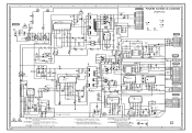
...: THIS SCHEMATIC DIAGRAM IS THE LATEST AT THE TIME NOTE:THE DC VOLTAGE AT EACH PART WAS MEASURED CRITICAL FOR SAFETY,USE ONES DANGEREUSES AN POINT DE VUE SECURITE OF PRINTING AND SUBJECT TO CHANGE WITHOUT NOTICE WITH THE DIGITAL TESTER WHEN THE COLOR BROADCAST DESCRIBED IN PARTS LIST ONLY N'UTILISER QUE CELLS DECRITES WAS RECEIVED IN GOOD CONDITION AND PICTURE IS...
...: THIS SCHEMATIC DIAGRAM IS THE LATEST AT THE TIME NOTE:THE DC VOLTAGE AT EACH PART WAS MEASURED CRITICAL FOR SAFETY,USE ONES DANGEREUSES AN POINT DE VUE SECURITE OF PRINTING AND SUBJECT TO CHANGE WITHOUT NOTICE WITH THE DIGITAL TESTER WHEN THE COLOR BROADCAST DESCRIBED IN PARTS LIST ONLY N'UTILISER QUE CELLS DECRITES WAS RECEIVED IN GOOD CONDITION AND PICTURE IS...

Service Manual
Page 43
... CRITICAL FOR SAFETY,USE ONES DESCRIBED IN PARTS LIST ONLY A B ATTENTION:LES PIECES REPAREES PAR UN ETANT DANGEREUSES AN POINT DE VUE SECURITE N'UTILISER QUE CELLS DECRITES DANS LA NOMENCLATURE DES PIECES C D NOTE:THE DC VOLTAGE AT EACH PART WAS MEASURED WITH THE DIGITAL TESTER WHEN THE COLOR BROADCAST WAS RECEIVED IN GOOD CONDITION AND PICTURE IS NORMAL.
... CRITICAL FOR SAFETY,USE ONES DESCRIBED IN PARTS LIST ONLY A B ATTENTION:LES PIECES REPAREES PAR UN ETANT DANGEREUSES AN POINT DE VUE SECURITE N'UTILISER QUE CELLS DECRITES DANS LA NOMENCLATURE DES PIECES C D NOTE:THE DC VOLTAGE AT EACH PART WAS MEASURED WITH THE DIGITAL TESTER WHEN THE COLOR BROADCAST WAS RECEIVED IN GOOD CONDITION AND PICTURE IS NORMAL.
Service Manual
Page 61
NOTE: THIS SCHEMATIC DIAGRAM IS THE LATEST AT THE TIME OF PRINTING AND SUBJECT TO CHANGE WITHOUT NOTICE NOTE:THE DC VOLTAGE AT EACH PART WAS MEASURED WITH THE DIGITAL TESTER WHEN THE COLOR BROADCAST WAS RECEIVED IN GOOD CONDITION AND PICTURE IS NORMAL. CAUTION:SINCE THESE PARTS MARKED BY ARE CRITICAL FOR SAFETY,USE ONES DESCRIBED IN PARTS LIST ONLY ATTENTION:LES PIECES...
NOTE: THIS SCHEMATIC DIAGRAM IS THE LATEST AT THE TIME OF PRINTING AND SUBJECT TO CHANGE WITHOUT NOTICE NOTE:THE DC VOLTAGE AT EACH PART WAS MEASURED WITH THE DIGITAL TESTER WHEN THE COLOR BROADCAST WAS RECEIVED IN GOOD CONDITION AND PICTURE IS NORMAL. CAUTION:SINCE THESE PARTS MARKED BY ARE CRITICAL FOR SAFETY,USE ONES DESCRIBED IN PARTS LIST ONLY ATTENTION:LES PIECES...
Service Manual
Page 63
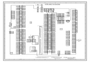
... 23 SOUND GND 4 4 SOUND GND CP506 1 +24V CP508 CD3806 CP3808 GND 7 7 GND NC 7 4 1 E E E 4 1 E E RED RED WHITE WHITE RED RED BLUE BLUE GREEN GREEN CP301 CP303 2 +24V GND 6 6 GND 7 3 +24V 4 +24V GND 5 DTV UNREG+4V 4 5 GND 4 DTV UNREG+4V CS_IN 4/5 J4211 AUDIO_IN 4/5 J4204 5 +24V 6 GND 7 GND 8 GND 9 GND 10 GND 11 NC 12 BL ON/OFF 13 Brightness Ctl NC 14 N.? SIGNAL...
... 23 SOUND GND 4 4 SOUND GND CP506 1 +24V CP508 CD3806 CP3808 GND 7 7 GND NC 7 4 1 E E E 4 1 E E RED RED WHITE WHITE RED RED BLUE BLUE GREEN GREEN CP301 CP303 2 +24V GND 6 6 GND 7 3 +24V 4 +24V GND 5 DTV UNREG+4V 4 5 GND 4 DTV UNREG+4V CS_IN 4/5 J4211 AUDIO_IN 4/5 J4204 5 +24V 6 GND 7 GND 8 GND 9 GND 10 GND 11 NC 12 BL ON/OFF 13 Brightness Ctl NC 14 N.? SIGNAL...
Service Manual
Page 71
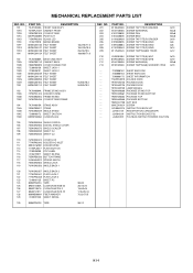
... SERIAL 50x35 20x15x12 15x50x16 17.5x20x14 7x3.2xT0.5 130 890MP2401E TAPE 50x12 REF. J3Y00431A INSTRUCTION BOOK(E/F/S) --- MECHANICAL REPLACEMENT PARTS LIST REF. A3Y004E975 INSTRUCTION BOOK KIT --- JA4ND200 POLYBAG INSTRUCTION(RED CAUTION) K1-1 NO. 201 202 203 204 205 206 207 208 209 PART NO. 8110630A0U 810A14080U 810213080S 810223080S 8110630A0S 810923080S 810923080U 8110230A4S 8117540A2U DESCRIPTION SCREW TAP TITE(P) BRAZIER SCREW WASHER(A) SCREW PAN SCREW BIND SCREW...
... SERIAL 50x35 20x15x12 15x50x16 17.5x20x14 7x3.2xT0.5 130 890MP2401E TAPE 50x12 REF. J3Y00431A INSTRUCTION BOOK(E/F/S) --- MECHANICAL REPLACEMENT PARTS LIST REF. A3Y004E975 INSTRUCTION BOOK KIT --- JA4ND200 POLYBAG INSTRUCTION(RED CAUTION) K1-1 NO. 201 202 203 204 205 206 207 208 209 PART NO. 8110630A0U 810A14080U 810213080S 810223080S 8110630A0S 810923080S 810923080U 8110230A4S 8117540A2U DESCRIPTION SCREW TAP TITE(P) BRAZIER SCREW WASHER(A) SCREW PAN SCREW BIND SCREW...


