Sharp LC-26SH10U Support Question
Sharp LC-26SH10U Support Question
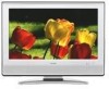
Find answers below for this question about Sharp LC-26SH10U - 26" LCD TV.Need a Sharp LC-26SH10U manual? We have 1 online manual for this item!
Question posted by johnnie0402 on September 28th, 2015
Replacement Screws For Stand
Replacement screws for Sharp LC-26SH10U stand...
Current Answers
Answer #1: Posted by TechSupport101 on September 29th, 2015 3:28 AM
TechSupport101

Member since:
May 24th, 2013 Points: 12,171,305

Member since:
May 24th, 2013 Points: 12,171,305
See the Service Manual here http://www.manualslib.com/manual/428333/Sharp-Lc-26sh10u-26-Lcd-Tv.html for the size specifications and try and order them from here http://www.sharpusa.com/CustomerSupport/SharpCareCenter/PartsAndService.aspx
Related Sharp LC-26SH10U Manual Pages
Service Manual - Page 1
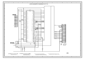
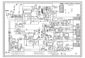
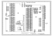
... • SCHEMATIC DIAGRAMS ...H-1~H-52 • WAVEFORMS ...I-1~I-3 • MECHANICAL EXPLODED VIEWS J-1~J-4 • REPLACEMENT PARTS LIST K1-1~K2-11
This document has been published to be used for after sales service only. The contents are subject to change without notice. #########
LCD COLOR TELEVISION
MODEL LC-26SH10U
In the interests of user-safety (Required by safety regulations in...
Service Manual - Page 2
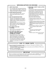
...PERFORM A SAFETY CHECK AFTER SERVICING
Confirm that the screws, parts and wiring which were removed in the... positions.
6. If the insulation resistance is replaced should be used the part which is flowing...serviced or not. BE CAREFUL WITH THE LCD PANEL
Avoid a shock to the IC and Transistor... heat sink, apply silicon grease (YG6260M) on the TV. 3. And be required.
[Note 1] If you ...
Service Manual - Page 4
... Signal
Output Level Input Level Output Level
at DVD at TV
Digital Output Level
S/N Ratio at DVD (Weighted)
Harmonic...Power
Power Source
AC
DC
Power Consumption
at AC
at DC
Stand by (at AC)
Energy Star
Per Year
Protector
Power Fuse
...
FCC/IC
--
0oC ~ +40oC
-20oC ~ +60oC
Less than
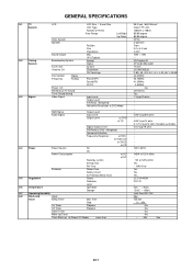
26.0 inch / 660.53mmV
Color TFT LCD
1366(H) x 768(V)
85/85 degree
85/85 degree
NTSC
2 Speaker...
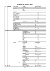
Service Manual - Page 6
...Comb Filter
Game Position
Auto Setup(Language/CH Program)
Picture Setting(TV)
AV Mode(Picture Preference)
Brightness , Contrast , Color
Tint
Sharpness
Color Temperature
Cable Clear
Picture Setting(PC)
BRIGHTNESS , CONTRAST
... CH
V-Chip
Type
RRT Setup
Lock
Hotel Lock
Channel Lock
Video Lock
Panel Lock
OSD Language
Closed Caption
CC Advanced
View Mode (Picture Size)
Picture...
Service Manual - Page 7
... Service Facility List Important Safeguard Dew/AHC Caution Sheet Quick Set-up Sheet Battery
AC Adapter
AC Cord (for AC Adapter)
AC Cord (Flat Polarity Plugs)
Cable Cramp
Stand
Stand Screw
Hexagon Wrench
AV Cord (2Pin-1Pin)
Registration Card (NDL Card)
300 to 75ohm Antenna Adapter
Switch
Top
Indicator Terminals
Rear Rear
Side
Language...
Service Manual - Page 8
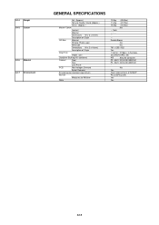
...)
Container Stuffing (40' container)
Cabinet
Front
Rear
Jack Panel
PCB
Non-Halogen Demand
Eyelet Demand
Environmental standard requirement
Pb...
---
--- G-14 Weight G-15 Carton
G-16 Material G-17 Environment
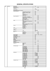
GENERAL SPECIFICATIONS
Net (Approx.)
Net w/o Handle, Stand (Approx.)
Gross (Approx.)
Master Carton
Content
Material
Dimensions W x D x H(mm)
Description of Origin
Gift Box
...
Service Manual - Page 9

...of arrow.
11 1
1
11
1 1
1
1
1 1
1
1 1 1
1 1
1
Back Cabinet
1-3: PCB ASS'Y (Refer to Fig. 1-3)
1. Remove the 9 screws 1. 3. Remove the Stand Ass'y in the direction of arrow (A). 3.
Fig. 1-1
1-2: STAND ASS'Y/ANGLE BACK 1/2/PLATE JACK 1/2 (Refer to Fig. 1-1)
1. Remove the 4 screws 1. 2. Remove the Plate Jack 2 in the direction of arrow (C). 8. Remove the Plate Jack 1 and...
Service Manual - Page 10

DISASSEMBLY INSTRUCTIONS
1-4: LCD COVER/LCD PANEL (Refer to Fig. 1-4)
1. Remove the 8 screws 1. 2. Remove the LCD Panel in the direction of arrow (B).
11
1
21
1
2 1 1
2
21 (B)
LCD Cover
Front Cabinet (A)
LCD Panel
Fig. 1-4
B1-2 Remove the LCD Cover in the direction of arrow (A). 3. Remove the 4 screws 2. 4.
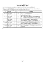
Service Manual - Page 13
...
VOL.
TV mode
VOL. NOTE: If you can repair, examine and adjust easily.
Releasing of MEMORY IC. Can be checked of the INITIAL DATA of V-CHIP PASSWORD. ALL mode
VOL. ALL mode
VOL.
DOWN (Minimum)
6
2 sec. Refer to the "ELECTRICAL ADJUSTMENT" (On-Screen Display Adjustment). Refer to the "WHEN REPLACING EEPROM (MEMORY...
Service Manual - Page 14
...remote control for more than 2 seconds. DOWN button on the set to the TV mode. 2. ADDRESS DATA
INIT 0000 00
LCD ON 0000
OEC7154B_010
DTV d0l63041
FIG. 2
4. Again, step through the ADDRESS until... DATA. Rom correction data check sum.
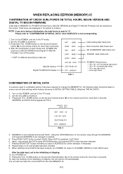
WHEN REPLACING EEPROM (MEMORY) IC
CONFIRMATION OF CHECK SUM, POWER ON TOTAL HOURS, MICON VERSION AND DIGITAL TV MICON FIRMWARE
Initial total of each check sum,...
Service Manual - Page 16
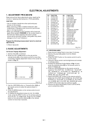
... adjustments when repairing the circuits or replacing electrical parts or PCB assemblies.
Prepare...FUNCTION 22 H POSI 60Hz 24 V POSI 60Hz 25 BAK LIGHT CENT 26 BAK LIGHT MAX 27 BAK LIGHT MIN 28 BRIGHT CENT 29 BRIGHT MAX.... Adjust the RIGHT/LEFT button on the remote control to put the wire back in Fig. 2-1. TV
01 H POSI OSD
346
Fig. 2-1
3. Press the UP/DOWN button on the remote control to...
Service Manual - Page 17

...
26
26
26
56
---
---
26
56
---
---
55
D-2 Step No. Step No. Step No. Step No. Step No. ELECTRICAL ADJUSTMENTS
2-2: Confirmation of Fixed Value (Step No.)
Please check if the fixed values of each of the adjustment items are set correctly referring below. (TV/AV/CS/HD-MI)
CS
HD-MI
TV TV 720p AV AV (S) 480i 480p...
Service Manual - Page 46
... 0 0 0 3.4 3.2 3.2 3.2
00
DVB_FAN_ON-H
0
R151
STEREO_RESET
10K
SCALER-H
SCALER_RESET R158
S_DET
SW_SCART IIC_OFF
R102 LCD-H AFT_1[LOW] AFT_2[HIGH] LCDON
AFT KEY-B KEY-A
DTUNER_H
R103 2.2K
R104 2.2K
C123 0.1 B 3.2
D101...
YUV_SW
EPM
COMPONENT/HDMI
NC
HDMI_H
NC
DVB_RX
28 SDA1
DVB_TX (RST1)
27 SCL1
(CLK1)
26 NC
DVD_RX
DVD_TX
0 NC
0 NC
0 JG102
0 JG105
0 JG106
0
0
R119
0
...
Service Manual - Page 47
... DPR6 DPR5 DPR4 DPR3 DPR2 DPR1 DPR0
DPG7
22
AFT_1
23
LCDON
24 DVB_FAN_ON-H
25 LCD-H/PDP_RLY
26
S_DET
W824 W875
AFT_1[LOW] LCDON
DVB_FAN_ON-H LCD-H S_DET
DDHS
C824 0.1 B C836
SW_CVBS
C837
C883 0.1 B C838
3.4 3.4
0 ...20
GND
21 DTUNER_POWER
22
GND
23 DTUNER_SD_H
24
GND
25 SWITCH_CVBS
26
GND
27 SWITCH_VIDEO_Y
28
GND
29 SWITCH_VIDEO_C
DVB_POWER_CTL-H
SD_H W931
W802
W930...
Service Manual - Page 49
...
18
RXIN2-
19
RXIN2+ 20
GND
21
RXCLK IN- 22
RXCLK IN+ 23
GND
24
RXIN3-
25
RXIN3+ 26
GND
27
NC VDD+3.3V/NC/GND 28
NC VDD+3.3V/NC/GND 29
NC/GND 30
VDD+3.3V/GND 31...
GND
32
CD7204 CHRU3002
LCD PANEL
V2301 LK260T3LF12
C7219 4V330 V-S
C7208 6.3V 220 V-S
C7209 6.3V 220 V-S
GND
1
CAUTION:SINCE THESE PARTS MARKED ...
Service Manual - Page 61
...0 Q505
KRC102SRTK
C541_1
HS506 763WAAA070
D540
L504 33uH7313N
6.5 KTC3875S_Y_RTK 0 R594
0 4.7K 0
AT+5V LCD-H
C568 16V 680 FM
EC31QS04
C560 16V 680 FM
D538 1SS355
2.7K +-1% 390 +-1% P.CON+5V...3.0 0 LCD5V_SW
Q514 KRC102SRTK
1
6.3A 125V
7A 250V
CAUTION :FOR CONTINUED PROTECTION AGAINST FIRE HAZARD, REPLACE ONLY WITH THE SAME TYPE FUSE 6.3A 125V(F501) AND 7A 250V(F502)
ATTENTION :POUR UNE ...
Service Manual - Page 63
...11
5
CLK+
10
NC DVB_FAN_ON-H 7 7
24 24 DVB_FAN_ON-H
D0-
9
CP2403
CP5801(CP2403)
NC
1 OOB
LCD-H/PDP_RLY 6 6
NC
S_DET
55
25 25 LCD-H/PDP_RLY
26 26
S_DET
SCALER PCB PCBDS0
D0-S
8
D0+
7
UNREG+5V 1
1 UNREG+5V
2 +5V
44
27 27
...
GND
18 18
12 12
GND
CP102
VDD+3.3V/NC/GND 10 TO LCD PANEL
AFT(0) 19
19 AFT_1
GND
2
2
GND
SW_AUDIO_L(PC) 17 17
13 13 SW_AUDIO_L(PC)
GND
1...
Service Manual - Page 69
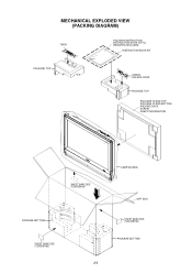
MECHANICAL EXPLODED VIEW (PACKING DIAGRAM)
TM101
POLYBAG INSTRUCTION, INSTRUCTION BOOK (E/F/S), REGISTRATION CARD
INSTRUCTION BOOK KIT
PACKAGE TOP
CD3810 HOLDER CORD
PACKAGE TOP
PACKAGE STAND-TOP PACKAGE STAND-BOTTOM PACKING SACK SCREW SHEET INFORMATION
SHEET BARCODE (7230008183)
PACKAGE BOTTOM
SHEET BARCODE (7230008182)
J-3
LAMIFILM BAG
GIFT BOX SHEET BARCODE (7230008183) PACKAGE BOTTOM
Service Manual - Page 70

MECHANICAL EXPLODED VIEW (PACKING DIAGRAM)
PACKAGE STAND-TOP
SHEET INFORMATION
PACKING SACK (791WHA0126)
SCREW
PACKING SACK (791WHA0125)
PACKAGE STAND-BOTTOM
J-4
Service Manual - Page 71
... PACKING SACK
---
791WHA0126 PACKING SACK
---
791WHA0130 LAMIFILM BAG
---
792WHA0660 PACKAGE STAND-TOP
---
792WHA0661 PACKAGE STAND-BOTTOM
---
792WHA0664 PACKAGE TOP
---
792WHA0665 PACKAGE BOTTOM
---
793WCD1758 GIFT BOX
---
890CDAIA24 SCREW
--- JA4ND200 POLYBAG INSTRUCTION(RED CAUTION)
K1-1 J3Y00417A REGISTRATION CARD(SHARP)
--- NO.
101 101A 101B 101C 101D 101E 101F 101G 101H...
Similar Questions

How Do I Assemble Tv Stand
assembly of tv stand for sharp tv lc26sh10u
assembly of tv stand for sharp tv lc26sh10u
(Posted by Littlenurseja 8 years ago)

Sharp Lc26sh10u Tv Manual
I want to mount the tv on a wall mount. Where are the correct holes to place the screws? I see 2 of ...
I want to mount the tv on a wall mount. Where are the correct holes to place the screws? I see 2 of ...
(Posted by rvsquared 10 years ago)


Sharp 26' Lcd Lc-26sb24u
I have a shrp 26" LCD tv model LC-26SB24U the the green light will come on for about 15-20 sec. then...
I have a shrp 26" LCD tv model LC-26SB24U the the green light will come on for about 15-20 sec. then...
(Posted by awoliver86 12 years ago)

Lcd Tv -- Lamp
Does the sharp LC42SB45UT LCD TV contain a lamp?The Sharp warranty will not cover a tech to come out...
Does the sharp LC42SB45UT LCD TV contain a lamp?The Sharp warranty will not cover a tech to come out...
(Posted by kles 12 years ago)