
Service Manual
Page 5
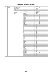
G-9 Remote Control GENERAL SPECIFICATIONS Unit Glow in Dark Remocon Remocon Format Format Custom Code Power Source Total Keys Keys Voltage(D.C) UM size x pcs POWER FUNCTION Source ...+ VOLCH+ CHSURROUND MUTE FREEZE MENU LEFT ENTER RIGHT UP DOWN EXIT RETURN FAVORITE A FAVORITE B FAVORITE C FAVORITE D FAVORITE SLEEP AUDIO AV MODE CC RC-MQ No SHARP SHARP 10000 / 10001 3V UM-3 x 2 pcs 40 Keys Yes No No Yes No No No No No No No No No Yes Yes Yes Yes Yes...
G-9 Remote Control GENERAL SPECIFICATIONS Unit Glow in Dark Remocon Remocon Format Format Custom Code Power Source Total Keys Keys Voltage(D.C) UM size x pcs POWER FUNCTION Source ...+ VOLCH+ CHSURROUND MUTE FREEZE MENU LEFT ENTER RIGHT UP DOWN EXIT RETURN FAVORITE A FAVORITE B FAVORITE C FAVORITE D FAVORITE SLEEP AUDIO AV MODE CC RC-MQ No SHARP SHARP 10000 / 10001 3V UM-3 x 2 pcs 40 Keys Yes No No Yes No No No No No No No No No Yes Yes Yes Yes Yes...
Service Manual
Page 7
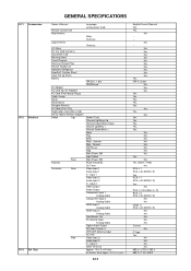
... 682.0 x 273.5 x 553.0 682.0 x 115 x 499.0 W x D x H (mm) A2-4 English/French/Spanish Yes Yes No --- G-11 Accessories G-12 Interface G-13 Set Size GENERAL SPECIFICATIONS Owner's Manual Remote Control Unit Rod Antenna Loop Antenna U/V Mixer DC Car Cord (Center+) Guarantee Card Warning Sheet Circuit Diagram Antenna Change Plug Service Facility List Important Safeguard...
... 682.0 x 273.5 x 553.0 682.0 x 115 x 499.0 W x D x H (mm) A2-4 English/French/Spanish Yes Yes No --- G-11 Accessories G-12 Interface G-13 Set Size GENERAL SPECIFICATIONS Owner's Manual Remote Control Unit Rod Antenna Loop Antenna U/V Mixer DC Car Cord (Center+) Guarantee Card Warning Sheet Circuit Diagram Antenna Change Plug Service Facility List Important Safeguard...
Service Manual
Page 13
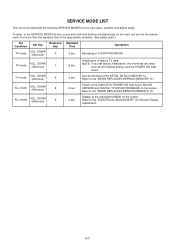
...Time Operations 2 sec. DOWN (Minimum) 8 2 sec. Can be checked of the INITIAL DATA of the SUM DATA, POWER ON total hours, MICON VERSION and DIGITAL TV MICON FIRMWARE on the screen. SERVICE MODE LIST This unit is provided with the following SERVICE MODES so you set factory initialization, the memories are... "WHEN REPLACING EEPROM (MEMORY) IC". Refer to the SERVICE MODE function, press and hold both buttons simultaneously on the main unit and on the remote control for more than the standard time in the appropriate condition. (See below chart.) Set Condition Set Key Remocon Key...
...Time Operations 2 sec. DOWN (Minimum) 8 2 sec. Can be checked of the INITIAL DATA of the SUM DATA, POWER ON total hours, MICON VERSION and DIGITAL TV MICON FIRMWARE on the screen. SERVICE MODE LIST This unit is provided with the following SERVICE MODES so you set factory initialization, the memories are... "WHEN REPLACING EEPROM (MEMORY) IC". Refer to the SERVICE MODE function, press and hold both buttons simultaneously on the main unit and on the remote control for more than the standard time in the appropriate condition. (See below chart.) Set Condition Set Key Remocon Key...
Service Manual
Page 14
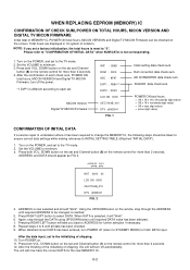
...Press RIGHT/LEFT button to minimum. 3. Using the UP/DOWN buton on the remote control for more than 2 seconds. 12. MICON Version Digital TV MICON Firmware INIT : C66D ROM : 0000 ADC : 8F97 DVP1 : F8B4 *1 DVP2 : 2D23 LCD ON 0000 OEC7154B_010 DTV d0l63041 FIG. 1 Initial setting data check sum. Turn POWER..., set and Channel button (8) on the remote, step through the DATA using UP/DOWN button until all data has been checked. 9. WHEN REPLACING EEPROM (MEMORY) IC CONFIRMATION OF CHECK SUM, POWER ON TOTAL HOURS, MICON VERSION AND DIGITAL TV MICON FIRMWARE Initial total of MEMORY IC, ...
...Press RIGHT/LEFT button to minimum. 3. Using the UP/DOWN buton on the remote control for more than 2 seconds. 12. MICON Version Digital TV MICON Firmware INIT : C66D ROM : 0000 ADC : 8F97 DVP1 : F8B4 *1 DVP2 : 2D23 LCD ON 0000 OEC7154B_010 DTV d0l63041 FIG. 1 Initial setting data check sum. Turn POWER..., set and Channel button (8) on the remote, step through the DATA using UP/DOWN button until all data has been checked. 9. WHEN REPLACING EEPROM (MEMORY) IC CONFIRMATION OF CHECK SUM, POWER ON TOTAL HOURS, MICON VERSION AND DIGITAL TV MICON FIRMWARE Initial total of MEMORY IC, ...
Service Manual
Page 16
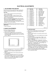
...CUTOFF (W) at each step tone sections equally. 8. Receive the gray scale pattern from the Pattern Generator. 3. Press the UP/DOWN button on the remote control to select the "R CUTOFF (N)", "B DRIVE (N)", "B CUTOFF (N)", "R DRIVE (C)", "R CUTOFF (C)", "B DRIVE (C)", "B CUTOFF (C)", "R DRIVE...20 B CUTOFF (W) NO. FUNCTION 22 H POSI 60Hz 24 V POSI 60Hz 25 BAK LIGHT CENT 26 BAK LIGHT MAX 27 BAK LIGHT MIN 28 BRIGHT CENT 29 BRIGHT MAX 30 BRIGHT MIN 31 TINT 35... Set the VOLUME to the IC and Transistor). TV 01 H POSI OSD 346 Fig. 2-1 3. NO. ELECTRICAL ADJUSTMENTS 1. Place the set the ...
...CUTOFF (W) at each step tone sections equally. 8. Receive the gray scale pattern from the Pattern Generator. 3. Press the UP/DOWN button on the remote control to select the "R CUTOFF (N)", "B DRIVE (N)", "B CUTOFF (N)", "R DRIVE (C)", "R CUTOFF (C)", "B DRIVE (C)", "B CUTOFF (C)", "R DRIVE...20 B CUTOFF (W) NO. FUNCTION 22 H POSI 60Hz 24 V POSI 60Hz 25 BAK LIGHT CENT 26 BAK LIGHT MAX 27 BAK LIGHT MIN 28 BRIGHT CENT 29 BRIGHT MAX 30 BRIGHT MIN 31 TINT 35... Set the VOLUME to the IC and Transistor). TV 01 H POSI OSD 346 Fig. 2-1 3. NO. ELECTRICAL ADJUSTMENTS 1. Place the set the ...


