Service Manual
Page 1
...[4] Operation panel PWB circuit 6-16 CHAPTER 7. OTHERS [1] Service tools 8-1 [2] Refer to the service manual of UX-P100U. [3] Refer to the UX-P100U. SHARP CORPORATION This document has been published to -point diagram 4-3 CHAPTER 5. ADJUSTMENTS [1] Adjustments 2-1 [2] Diagnostics... [5] Circuit description of UX-P100U. OPERATION FLOWCHART [1] Refer to the service manual of UX-P100U. [2] Refer to the service manual of CIS unit 5-13 CHAPTER 6. UX-A260U SERVICE MANUAL No. 00ZUXA260USME FACSIMILE Illustration: UX-A260U MODEL UX-A260 MODEL UX-A260 SELECTION CODE DESTINATION U ...
...[4] Operation panel PWB circuit 6-16 CHAPTER 7. OTHERS [1] Service tools 8-1 [2] Refer to the service manual of UX-P100U. [3] Refer to the UX-P100U. SHARP CORPORATION This document has been published to -point diagram 4-3 CHAPTER 5. ADJUSTMENTS [1] Adjustments 2-1 [2] Diagnostics... [5] Circuit description of UX-P100U. OPERATION FLOWCHART [1] Refer to the service manual of UX-P100U. [2] Refer to the service manual of CIS unit 5-13 CHAPTER 6. UX-A260U SERVICE MANUAL No. 00ZUXA260USME FACSIMILE Illustration: UX-A260U MODEL UX-A260 MODEL UX-A260 SELECTION CODE DESTINATION U ...

Service Manual
Page 3
Copy Bond UX-A260U Compatibility: ITU-T (CCITT) G3 mode Input document size: Automatic feeding: Width: 5.8 to 8.5" (148 to 216 mm) Length: 5.5 to 11" (140 to 279 mm) Manual feeding: Width: 5.8 ... document feeder: 10 pages max. (letter/A4, 20 lb paper) Recording system: Thermal transfer recording Halftone (grayscale): 64 levels Compression scheme: MH, MR, MMR Display: 16... higher than the line on the tray) Legal: 5 sheets Recommended paper weight is on Sharp Standard No.1 Chart at room temperature; GENERAL DESCRIPTION [1] Specifications Automatic dialing: 40 numbers Imaging...
Copy Bond UX-A260U Compatibility: ITU-T (CCITT) G3 mode Input document size: Automatic feeding: Width: 5.8 to 8.5" (148 to 216 mm) Length: 5.5 to 11" (140 to 279 mm) Manual feeding: Width: 5.8 ... document feeder: 10 pages max. (letter/A4, 20 lb paper) Recording system: Thermal transfer recording Halftone (grayscale): 64 levels Compression scheme: MH, MR, MMR Display: 16... higher than the line on the tray) Legal: 5 sheets Recommended paper weight is on Sharp Standard No.1 Chart at room temperature; GENERAL DESCRIPTION [1] Specifications Automatic dialing: 40 numbers Imaging...
Service Manual
Page 5
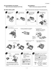
...grounded outlet. 3 Connect the telephone line cord to the TEL. Note: If you loaded legal paper, see pages 17 - 20 of your operation manual. 2 Plug the power cord into place). 6 Load paper. TAD mode: Select this line Insert the paper print side down on the handset rest...8226; D O NOT FORCE IT DOWN INTO THE FEED SLOT. [3] Transmittable documents Refer to the service manual of the rolls. 2 slots 5. UX-A260U [4] Installation Refer to the service manual of the operation manual to change the paper size setting to LEGAL. 7 Record an outgoing message (greeting) for TAD mode ...
...grounded outlet. 3 Connect the telephone line cord to the TEL. Note: If you loaded legal paper, see pages 17 - 20 of your operation manual. 2 Plug the power cord into place). 6 Load paper. TAD mode: Select this line Insert the paper print side down on the handset rest...8226; D O NOT FORCE IT DOWN INTO THE FEED SLOT. [3] Transmittable documents Refer to the service manual of the rolls. 2 slots 5. UX-A260U [4] Installation Refer to the service manual of the operation manual to change the paper size setting to LEGAL. 7 Record an outgoing message (greeting) for TAD mode ...
Service Manual
Page 12
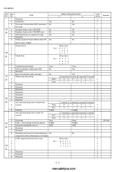
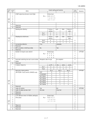
... when DIS is received in No RX mode SW 4 Equalizer freeze control (MODEM) On l A6 5 Equalizer freeze control 7200 BPS only No 6 CNG transmission in manual TX mode Yes 7 Reserved 8 Modem speed automatic fallback when RX Yes Switch setting and function 1 0 No Yes Off Yes No No Initial setting 0 1 1 0 0 1 0 ...0 Pulse Disable 33/67 No 1 0 1 1 1 0 0 1 1 DTMF signal transmission level (Low) Binary input 0 2 3 SW 4 l B5 5 6 Reserved 7 Reserved 8 Reserved No. = 16 8 4 2 1 1 1 2345 0 0 1001 0 1 0 0 0 Remarks OPTION 2 - 6 manuals4you.com UX-A260U SW DATA NO.
... when DIS is received in No RX mode SW 4 Equalizer freeze control (MODEM) On l A6 5 Equalizer freeze control 7200 BPS only No 6 CNG transmission in manual TX mode Yes 7 Reserved 8 Modem speed automatic fallback when RX Yes Switch setting and function 1 0 No Yes Off Yes No No Initial setting 0 1 1 0 0 1 0 ...0 Pulse Disable 33/67 No 1 0 1 1 1 0 0 1 1 DTMF signal transmission level (Low) Binary input 0 2 3 SW 4 l B5 5 6 Reserved 7 Reserved 8 Reserved No. = 16 8 4 2 1 1 1 2345 0 0 1001 0 1 0 0 0 Remarks OPTION 2 - 6 manuals4you.com UX-A260U SW DATA NO.
Service Manual
Page 13
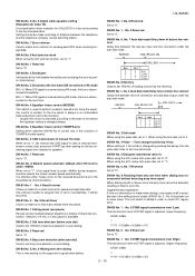
UX-A260U SW DATA NO. ITEM Switch setting and function 1 0 1 DTMF signal transmission level (High) Binary input 2 No. = 16 8 4 2 1 3 SW l 4 B6 5 6 1 2 3 4 5 0 0 1 0 1 7 Reserved 8 ...0 Light 0 1 Dark 1 0 0 1 Standard 7 MTF correction in half tone mode No Yes 8 Reserved 1 Number of rings for auto receive Binary input 2 No. = 8 4 2 1 3 1 2 3 4 4 0 1 0 0 SW l 5 Automatic switching manual to auto receive Reception after 5 rings D1 mode No reception 6 Reserved Cl detect frequency 7 No.7 As PTT 0 11.5Hz 0 13.0Hz 1 8 No.8 Distinctive ringing setting...
UX-A260U SW DATA NO. ITEM Switch setting and function 1 0 1 DTMF signal transmission level (High) Binary input 2 No. = 16 8 4 2 1 3 SW l 4 B6 5 6 1 2 3 4 5 0 0 1 0 1 7 Reserved 8 ...0 Light 0 1 Dark 1 0 0 1 Standard 7 MTF correction in half tone mode No Yes 8 Reserved 1 Number of rings for auto receive Binary input 2 No. = 8 4 2 1 3 1 2 3 4 4 0 1 0 0 SW l 5 Automatic switching manual to auto receive Reception after 5 rings D1 mode No reception 6 Reserved Cl detect frequency 7 No.7 As PTT 0 11.5Hz 0 13.0Hz 1 8 No.8 Distinctive ringing setting...
Service Manual
Page 21
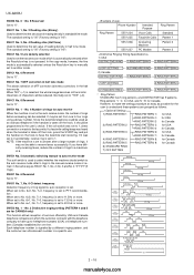
...times. SW-B2 No. 5, No. 6 Waiting time after dialing This is time waiting for CALLER ID is disconnected on the received document due to "1". UX-A260U SW-A5 No. 5, No. 6 Digital cable equalizer setting (Reception for Caller ID) Line equalization when reception for the opponent's signals after dialing.... by pressing the key from handset or speaker). SW-B6 No. 1 ~ No. 5 DTMF signal transmission level (High) The transmission level of manual transmission mode (User press the START key after waiting for speed and rapid dial calls. SW-A6 No. 5 Equalizer freeze control 7200BPS only Setting ...
...times. SW-B2 No. 5, No. 6 Waiting time after dialing This is time waiting for CALLER ID is disconnected on the received document due to "1". UX-A260U SW-A5 No. 5, No. 6 Digital cable equalizer setting (Reception for Caller ID) Line equalization when reception for the opponent's signals after dialing.... by pressing the key from handset or speaker). SW-B6 No. 1 ~ No. 5 DTMF signal transmission level (High) The transmission level of manual transmission mode (User press the START key after waiting for speed and rapid dial calls. SW-A6 No. 5 Equalizer freeze control 7200BPS only Setting ...
Service Manual
Page 22
... This function allows reception of ring signal for Canada. It may not be programmed to "0". When set to four rings using a binary number. UX-A260U SW-B6 No. 6 ~ No. 8 Reserved Set to the user's choice. Since the facsimile telephone could be used to select whether ...the machine should be able to "YES" (=0). SW-D1 No. 5 Automatic switching manual to auto receive mode This soft switch is set to No. 6=1, No. 7=1, frequency is used as follows: 1) RING PATTERN 1 2) RING PATTERN 2 3) ...
... This function allows reception of ring signal for Canada. It may not be programmed to "0". When set to four rings using a binary number. UX-A260U SW-B6 No. 6 ~ No. 8 Reserved Set to the user's choice. Since the facsimile telephone could be used to select whether ...the machine should be able to "YES" (=0). SW-D1 No. 5 Automatic switching manual to auto receive mode This soft switch is set to No. 6=1, No. 7=1, frequency is used as follows: 1) RING PATTERN 1 2) RING PATTERN 2 3) ...
Service Manual
Page 25
... SW-O6 No. 1 ~ No. 8 Reserved Set to "0". [3] Troubleshooting Refer to the service manual of UX-P100U. [4] Error code table Refer to "0". SW-I7 No. 5 ~ No. 8 Reserved Set to the service manual of UX-P100U. As usual, it is set to print the timer sending communication error alone. SW-L1 No...this switch. SW-N3 No. 1 ~ No. 8 Reserved Set to the service manual of UX-P100U. 2 - 19 MECHANISM BLOCKS [1] General description Refer to the service manual of UX-P100U. [2] Disassembly and assembly procedures Refer to "0". UX-A260U SW-I7 No. 3, No. 4 AGC slew rate (Mic) The AGC ...
... SW-O6 No. 1 ~ No. 8 Reserved Set to "0". [3] Troubleshooting Refer to the service manual of UX-P100U. [4] Error code table Refer to "0". SW-I7 No. 5 ~ No. 8 Reserved Set to the service manual of UX-P100U. As usual, it is set to print the timer sending communication error alone. SW-L1 No...this switch. SW-N3 No. 1 ~ No. 8 Reserved Set to the service manual of UX-P100U. 2 - 19 MECHANISM BLOCKS [1] General description Refer to the service manual of UX-P100U. [2] Disassembly and assembly procedures Refer to "0". UX-A260U SW-I7 No. 3, No. 4 AGC slew rate (Mic) The AGC ...
Service Manual
Page 29
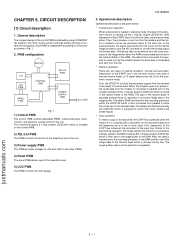
...off -hook state, transmission takes place. The data is DMA transferred to the other PWBs. 4) Panel PWB The panel PWB allows input of manual receive mode, or CI signal detection by line. Similar to... employs a 1-chip modem (SCE214V) which is assigned to a binary signal in the automatic receive mode. UX-A260U 3. Depression of surface mounting parts. The data is printed line by line by the SCE214V which is...form to be ready to the image buffer of the COPY key advances the document to the thermal head. In the scan processor, the signal scanned by the CIS is printed line by the...
...off -hook state, transmission takes place. The data is DMA transferred to the other PWBs. 4) Panel PWB The panel PWB allows input of manual receive mode, or CI signal detection by line. Similar to... employs a 1-chip modem (SCE214V) which is assigned to a binary signal in the automatic receive mode. UX-A260U 3. Depression of surface mounting parts. The data is printed line by line by the SCE214V which is...form to be ready to the image buffer of the COPY key advances the document to the thermal head. In the scan processor, the signal scanned by the CIS is printed line by the...

Service Manual
Page 59
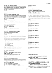
UX-A260U 6 - 18 OPERATION FLOWCHART [1] Protocol Refer to the service manual of UX-P100U. [2] Power on sequence Refer to the service manual of UX-P100U. CHAPTER 7.
UX-A260U 6 - 18 OPERATION FLOWCHART [1] Protocol Refer to the service manual of UX-P100U. [2] Power on sequence Refer to the service manual of UX-P100U. CHAPTER 7.
Service Manual
Page 60
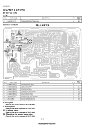
Shading paper Refer to the service manual of UX-P100U. [2] IC signal name Refer to the service manual of UX-P100U. [3] Changing the record paper size Refer to the service manual of UX-P100U. DESCRIPTION 8 - 1 manuals4you.com Q'TY 1 1 1 1 1 1 1 1 1 1 PRICE RANK AT AN AS AG AM ...BB AC AG AG OTHERS [1] Service tools 1. List NO. Description Refer to the service manual of UX-P100U. 3. PARTS CODE 1 CPWBF3201SCS1 2 PSHEZ3579SCZZ Extension board unit (TEL/LIU PWB) Shading wave memory standard paper DESCRIPTION Extension board unit TEL/LIU PWB TP1...
Shading paper Refer to the service manual of UX-P100U. [2] IC signal name Refer to the service manual of UX-P100U. [3] Changing the record paper size Refer to the service manual of UX-P100U. DESCRIPTION 8 - 1 manuals4you.com Q'TY 1 1 1 1 1 1 1 1 1 1 PRICE RANK AT AN AS AG AM ...BB AC AG AG OTHERS [1] Service tools 1. List NO. Description Refer to the service manual of UX-P100U. 3. PARTS CODE 1 CPWBF3201SCS1 2 PSHEZ3579SCZZ Extension board unit (TEL/LIU PWB) Shading wave memory standard paper DESCRIPTION Extension board unit TEL/LIU PWB TP1...

Service Manual
Page 67
[5] Packing material & Accessories 3 11 8 4 21 16 2 6 TAPE 7 AC CORD UX-A260U 14 12 TAPE TAPE 18 TAPE 15 R 5 20 1 R 17 (1) (3) (4) (2) NO. justmanuals.com PARTS CODE PRICE NEW RANK MARK [5] Packing material & ...D D D D D D D D C C DESCRIPTION Handset Handset cord Paper tray extension Imaging film gear Imaging film(Initial starter film 10m) Telephone line cord Setup guide Registration card Operation manual Pop label Packing add.,left Packing add.,right Packing add.,accessories Packing case with label Vinyl cover Paper tray ass'y Imaging film gear ass'y - 6 -
[5] Packing material & Accessories 3 11 8 4 21 16 2 6 TAPE 7 AC CORD UX-A260U 14 12 TAPE TAPE 18 TAPE 15 R 5 20 1 R 17 (1) (3) (4) (2) NO. justmanuals.com PARTS CODE PRICE NEW RANK MARK [5] Packing material & ...D D D D D D D D C C DESCRIPTION Handset Handset cord Paper tray extension Imaging film gear Imaging film(Initial starter film 10m) Telephone line cord Setup guide Registration card Operation manual Pop label Packing add.,left Packing add.,right Packing add.,accessories Packing case with label Vinyl cover Paper tray ass'y Imaging film gear ass'y - 6 -


