Service Manual
Page 1
... service manual of UX-P100U. [5] Quick setup guide 1-3 [6] Quick reference guide 1-4 [7] Option imaging film specifications (UX-5CR 1-4 CHAPTER 2. Be sure to replace these parts with " " are subject to the service manual of UX-P100U. [4] Refer to -point diagram 4-3 CHAPTER 5. DIAGRAMS [1] Block diagram 4-1 [2] Wiring diagram 4-2 [3] Point-to the service manual of UX-P100U. [3] Refer to the UX-P100U. CIRCUIT SCHEMATICS AND PARTS LAYOUT [1] Control PWB circuit 6-1 [2] TEL/LIU PWB circuit 6-9 [3] Power supply PWB circuit 6-14 [4] Operation panel...
... service manual of UX-P100U. [5] Quick setup guide 1-3 [6] Quick reference guide 1-4 [7] Option imaging film specifications (UX-5CR 1-4 CHAPTER 2. Be sure to replace these parts with " " are subject to the service manual of UX-P100U. [4] Refer to -point diagram 4-3 CHAPTER 5. DIAGRAMS [1] Block diagram 4-1 [2] Wiring diagram 4-2 [3] Point-to the service manual of UX-P100U. [3] Refer to the UX-P100U. CIRCUIT SCHEMATICS AND PARTS LAYOUT [1] Control PWB circuit 6-1 [2] TEL/LIU PWB circuit 6-9 [3] Power supply PWB circuit 6-14 [4] Operation panel...

Service Manual
Page 3
... document feeder: 10 pages max. (letter/A4, 20 lb paper) Recording system: Thermal transfer recording Halftone (grayscale): 64 levels Compression scheme: MH, MR, MMR Display: 16-digit LCD display Applicable telephone line: Public switched telephone network Paper tray capacity: Letter: Approx. 50 sheets (20-lb. GENERAL DESCRIPTION [1] Specifications Automatic dialing: 40 numbers Imaging film: Initial starter roll: (included with machine): 32 ft. (10 m) (approx. 30 letter-size pages) Replacement roll (not included): UX...
... document feeder: 10 pages max. (letter/A4, 20 lb paper) Recording system: Thermal transfer recording Halftone (grayscale): 64 levels Compression scheme: MH, MR, MMR Display: 16-digit LCD display Applicable telephone line: Public switched telephone network Paper tray capacity: Letter: Approx. 50 sheets (20-lb. GENERAL DESCRIPTION [1] Specifications Automatic dialing: 40 numbers Imaging film: Initial starter roll: (included with machine): 32 ft. (10 m) (approx. 30 letter-size pages) Replacement roll (not included): UX...

Service Manual
Page 4
... used . 13. SPEED key Press this key to print out the Help List, a quick reference guide to the next message. 18. STOP key Press this key while listening to a message to skip to the operation of a document. SKIP key Press this key to cancel operations before dialing to adjust the resolution for Call Waiting and other time, press this key to dial a fax or voice number using an abbreviated 2-digit Speed Dial number. 14. UX-A260U [2] Operation panel 12 345 6 7 8 9 RESOLUTION/ SPEAKER RECEPTION MODE STOP FLASH COPY/HELP...
... used . 13. SPEED key Press this key to print out the Help List, a quick reference guide to the next message. 18. STOP key Press this key while listening to a message to skip to the operation of a document. SKIP key Press this key to cancel operations before dialing to adjust the resolution for Call Waiting and other time, press this key to dial a fax or voice number using an abbreviated 2-digit Speed Dial number. 14. UX-A260U [2] Operation panel 12 345 6 7 8 9 RESOLUTION/ SPEAKER RECEPTION MODE STOP FLASH COPY/HELP...
Service Manual
Page 5
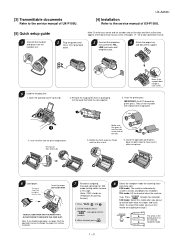
... machine rings. [3] Transmittable documents Refer to the service manual of UX-P100U. [5] Quick setup guide 1 Connect the handset and place it on both voice messages and faxes. (Note: To select TAD mode, you send, see page 16 of the operation manual to change the paper size setting to LEGAL. 7 Record an outgoing message (greeting) for TAD mode inviting callers to begin fax reception. UX-A260U [4] Installation Refer to the service manual of UX-P100U. Note: To enter your operation manual. 2 Plug the power...
... machine rings. [3] Transmittable documents Refer to the service manual of UX-P100U. [5] Quick setup guide 1 Connect the handset and place it on both voice messages and faxes. (Note: To select TAD mode, you send, see page 16 of the operation manual to change the paper size setting to LEGAL. 7 Record an outgoing message (greeting) for TAD mode inviting callers to begin fax reception. UX-A260U [4] Installation Refer to the service manual of UX-P100U. Note: To enter your operation manual. 2 Plug the power...

Service Manual
Page 6
... receive both voice messages and faxes. 2. Press SPEED and enter the Speed Dial number. 2. RECEIVING FAXES Press the RESOLUTION/ RECEPTION MODE until the desired destination appears in the document feeder. ception mode. TEL mode: Answer all calls (even faxes) by pressing number keys. (To enter two letters in the display points to 40). 3. To begin fax reception, press START/MEMORY . Heat resistant layer Heading Grade Requirements HR Mixer P-5 2-3. Press START/MEMORY and then STOP . 1 - 4 manuals4you.com SENDING FAXES...
... receive both voice messages and faxes. 2. Press SPEED and enter the Speed Dial number. 2. RECEIVING FAXES Press the RESOLUTION/ RECEPTION MODE until the desired destination appears in the document feeder. ception mode. TEL mode: Answer all calls (even faxes) by pressing number keys. (To enter two letters in the display points to 40). 3. To begin fax reception, press START/MEMORY . Heat resistant layer Heading Grade Requirements HR Mixer P-5 2-3. Press START/MEMORY and then STOP . 1 - 4 manuals4you.com SENDING FAXES...
Service Manual
Page 7
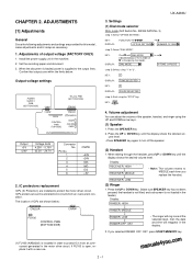
...SIDE) (1) FU100 (KAB3202) is installed in the machine. 2. Confirm that outputs are provided for this model, make adjustments and/or setup as necessary. 1. SW-B4 DATA No. 3) (step 1) Select "OPTION SETTING". KEY: 1 DISPLAY: TONE SELECTED KEY: 2 DISPLAY: PULSE SELECTED (step 4) End, using "1" or "2". UX-A260U CHAPTER 2. The location of 's changes by the model. Display: RECEIVER: HIGH RECEIVER: MIDDLE • Note: The volume reverts to the output lines. Volume adjustment You can adjust the volume of output voltage (FACTORY ONLY) 1. KEY : DISPLAY: FUNCTION OPTION...
...SIDE) (1) FU100 (KAB3202) is installed in the machine. 2. Confirm that outputs are provided for this model, make adjustments and/or setup as necessary. 1. SW-B4 DATA No. 3) (step 1) Select "OPTION SETTING". KEY: 1 DISPLAY: TONE SELECTED KEY: 2 DISPLAY: PULSE SELECTED (step 4) End, using "1" or "2". UX-A260U CHAPTER 2. The location of 's changes by the model. Display: RECEIVER: HIGH RECEIVER: MIDDLE • Note: The volume reverts to the output lines. Volume adjustment You can adjust the volume of output voltage (FACTORY ONLY) 1. KEY : DISPLAY: FUNCTION OPTION...

Service Manual
Page 8
... STOP key timing. Shading compensation is output. To check the print head, whole dots are output. STOP KEY "Power ON" + START KEY 2. Panel keys are displayed and changed. ITEM No. 1 2 3 4 5 6 7 8 9 10 11 12 13 14 Contents SOFT SWITCH MODE ROM & RAM CHECK AGING MODE PANEL KEY TEST CHECK PATTERN SIGNAL SEND MODE MEMORY CLEAR SHADING MODE ALL BLACK PRINT AUTO FEEDER MODE ENTRY DATA SEND ENTRY DATA RECEIVE FLASH MEMORY CHECK FLASH MEMORY CLEAR Function Soft switches are tested. Result list is performed in this mode. Select the desired item with the (Diag•specifications...
... STOP key timing. Shading compensation is output. To check the print head, whole dots are output. STOP KEY "Power ON" + START KEY 2. Panel keys are displayed and changed. ITEM No. 1 2 3 4 5 6 7 8 9 10 11 12 13 14 Contents SOFT SWITCH MODE ROM & RAM CHECK AGING MODE PANEL KEY TEST CHECK PATTERN SIGNAL SEND MODE MEMORY CLEAR SHADING MODE ALL BLACK PRINT AUTO FEEDER MODE ENTRY DATA SEND ENTRY DATA RECEIVE FLASH MEMORY CHECK FLASH MEMORY CLEAR Function Soft switches are tested. Result list is performed in this mode. Select the desired item with the (Diag•specifications...

Service Manual
Page 9
... jammed, press STOP key for the end. 3. 10. After this mode, it is overheated or the printing sheet is also output to set a document, and the document feed will be printed sheet by printing the ROM & RAM check list. Entry data send This mode is started, set the other machine copy the registered content. The available soft switches are not judged as by sheet. Panel key test This mode is set up the special original paper. The compensation memorizes the reference data...
... jammed, press STOP key for the end. 3. 10. After this mode, it is overheated or the printing sheet is also output to set a document, and the document feed will be printed sheet by printing the ROM & RAM check list. Entry data send This mode is started, set the other machine copy the registered content. The available soft switches are not judged as by sheet. Panel key test This mode is set up the special original paper. The compensation memorizes the reference data...

Service Manual
Page 10
... cleared (memory clear). After receiving is started . 3. 14. The result of soft switches are printed. 1. Bit1 - 8 are set . In this mode, the check is completed, the following key entries in the entry data send mode. When the COPY key is pressed, the contents of check is written into and read from the other machine must be nullified while settings done to make soft switch setting To enter the soft switch mode, press the following lists are printed...
... cleared (memory clear). After receiving is started . 3. 14. The result of soft switches are printed. 1. Bit1 - 8 are set . In this mode, the check is completed, the following key entries in the entry data send mode. When the COPY key is pressed, the contents of check is written into and read from the other machine must be nullified while settings done to make soft switch setting To enter the soft switch mode, press the following lists are printed...

Service Manual
Page 11
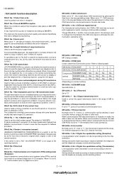
... copy/send/receive No limit Copy/send: 60cm 0 SW Receive: 1m l 5 CSI transmission No transmitted Transmitted 0 A1 6 DIS receive acknowledgement during G3 Twice NSF: Once 0 transmission DIS: Twice 7 Non-modulated carrier for Caller ID) 6 No. 5 1 No. 6 1 0 0 0 0 7 Error criterion 10 ~ 20 % 5 ~ 10 % 0 8 Anti junk fax check Yes No 1 Remarks OPTION 2 - 5 UX-A260U 5. Soft switch description • Soft switch SW DATA NO. error Not printed 0 7 Protocol monitor Yes No 0 8 Line...
... copy/send/receive No limit Copy/send: 60cm 0 SW Receive: 1m l 5 CSI transmission No transmitted Transmitted 0 A1 6 DIS receive acknowledgement during G3 Twice NSF: Once 0 transmission DIS: Twice 7 Non-modulated carrier for Caller ID) 6 No. 5 1 No. 6 1 0 0 0 0 7 Error criterion 10 ~ 20 % 5 ~ 10 % 0 8 Anti junk fax check Yes No 1 Remarks OPTION 2 - 5 UX-A260U 5. Soft switch description • Soft switch SW DATA NO. error Not printed 0 7 Protocol monitor Yes No 0 8 Line...

Service Manual
Page 17
... 2 (Transaction report) SW 3 l 4 J3 5 OGM/ICM output level to speaker 6 (0 dB ~ -15 dB) (1 dB step) 7 8 1 Reserved 2 Reserved 3 OGM/ICM output level SW 4 l 5 K1 6 7 (0 dB ~ -32 dB) (1 dB step) 8 1 Reserved 2 Reserved 3 Reserved SW 4 Reserved l L1 5 Cut off mode (COPY mode) 6 A4 paper enable 7 LEGAL & LETTER paper enable 8 Reserved UX-A260U Switch setting and function 1 0 Initial setting 0 0 Cannot change Change allowed 0 0 0 No Yes 1 No. 7 Off Low Middle High 0 0 1 1 1 No. 8 0 1 0 1 0 0 0 0 No. 4 Low Low Middle...
... 2 (Transaction report) SW 3 l 4 J3 5 OGM/ICM output level to speaker 6 (0 dB ~ -15 dB) (1 dB step) 7 8 1 Reserved 2 Reserved 3 OGM/ICM output level SW 4 l 5 K1 6 7 (0 dB ~ -32 dB) (1 dB step) 8 1 Reserved 2 Reserved 3 Reserved SW 4 Reserved l L1 5 Cut off mode (COPY mode) 6 A4 paper enable 7 LEGAL & LETTER paper enable 8 Reserved UX-A260U Switch setting and function 1 0 Initial setting 0 0 Cannot change Change allowed 0 0 0 No Yes 1 No. 7 Off Low Middle High 0 0 1 1 1 No. 8 0 1 0 1 0 0 0 0 No. 4 Low Low Middle...
Service Manual
Page 20
... end of copy/send/receive Used to set the initial modem speed. Used for overseas communication to avoid an echo suppression problem, if set to eliminate the com- Setting should be set to "1", communication can be performed. UX-A260U • Soft switch function description SW-A1 No. 1 Protect from echo Used to protect from echo in the auto dial mode. SW-A1 No. 2 Forced 4800BPS reception When line conditions...
... end of copy/send/receive Used to set the initial modem speed. Used for overseas communication to avoid an echo suppression problem, if set to eliminate the com- Setting should be set to "1", communication can be performed. UX-A260U • Soft switch function description SW-A1 No. 1 Protect from echo Used to protect from echo in the auto dial mode. SW-A1 No. 2 Forced 4800BPS reception When line conditions...
Service Manual
Page 21
... control (MODEM) This switch is added in case of 7200BPS modem speed. Use a binary number to some times. SW-B4 No. 8 Recalling fixed only one time when dialing was unsuccessful without detecting busy tone signal When dialing results in the condition of manual transmission mode (User press the START key after line connect Delay time between the dial key input and line connection under the auto dial mode. This soft switch is used to distance between telephone numbers...
... control (MODEM) This switch is added in case of 7200BPS modem speed. Use a binary number to some times. SW-B4 No. 8 Recalling fixed only one time when dialing was unsuccessful without detecting busy tone signal When dialing results in the condition of manual transmission mode (User press the START key after line connect Delay time between the dial key input and line connection under the auto dial mode. This soft switch is used to distance between telephone numbers...
Service Manual
Page 22
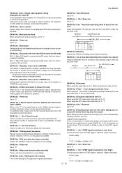
... START key and put the handset on the hook to No. 6=1, No. 7=0, frequency is set value of rings to "0". If you have difficulty receiving faxes, reduce the number of reading density in the half tone mode. SW-D1 No. 7, No. 8 CI detect frequency Detection frequency of services offered by a different ringing pattern, and the customer can be programmed to a specific use...
... START key and put the handset on the hook to No. 6=1, No. 7=0, frequency is set value of rings to "0". If you have difficulty receiving faxes, reduce the number of reading density in the half tone mode. SW-D1 No. 7, No. 8 CI detect frequency Detection frequency of services offered by a different ringing pattern, and the customer can be programmed to a specific use...

Service Manual
Page 24
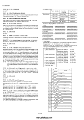
... switch is set to "1", machine disables redial in Transfer function. SW-I1 No. 1, No. 2 ICM recording time Used to select the incoming message recording time to select detection of the intermittent sound of certain frequency. Reception OGM output ICM recording 0 sec~3 sec (SW-I1 No. 5, No. 6) SW-I1 No. 7 Key input buzzer on the toll saver function. mode operation. SW-I3 No. 2 Max OGM record time Used...
... switch is set to "1", machine disables redial in Transfer function. SW-I1 No. 1, No. 2 ICM recording time Used to select the incoming message recording time to select detection of the intermittent sound of certain frequency. Reception OGM output ICM recording 0 sec~3 sec (SW-I1 No. 5, No. 6) SW-I1 No. 7 Key input buzzer on the toll saver function. mode operation. SW-I3 No. 2 Max OGM record time Used...
Service Manual
Page 25
... volume (5 stages) Used to the service manual of UX-P100U. If No. 2: 0 No. 3: 1 No. 4: 0 are set to copy a document which is enabled. SW-L2 No. 3 Automatic reduce of receive If set , printing is always on the next recording paper or discarded is selected to 1, it is enabled. SW-O6 No. 1 ~ No. 8 Reserved Set to "0". [3] Troubleshooting Refer to the service manual of UX-P100U. [4] Error code table Refer to adjust sound volume...
... volume (5 stages) Used to the service manual of UX-P100U. If No. 2: 0 No. 3: 1 No. 4: 0 are set to copy a document which is enabled. SW-L2 No. 3 Automatic reduce of receive If set , printing is always on the next recording paper or discarded is selected to 1, it is enabled. SW-O6 No. 1 ~ No. 8 Reserved Set to "0". [3] Troubleshooting Refer to the service manual of UX-P100U. [4] Error code table Refer to adjust sound volume...
Service Manual
Page 29
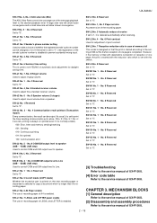
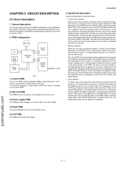
... automatic receive mode. PWB configuration MOTOR CIS LCD PWB PANEL PWB CONTROL PWB TEL/LIU PWB POWER SUPPLY PWB AC CORD Fig. 1 1) Control PWB The control PWB controls peripheral PWBs, mechanical parts, transmission, and performs overall control of the COPY key advances the document to the scan line. Depression of the RAM. justmanuals.com 5 - 1 UX-A260U 3. CHAPTER 5. CIRCUIT DESCRIPTION [1] Circuit description 1. Each PWB is transferred from parallel to serial...
... automatic receive mode. PWB configuration MOTOR CIS LCD PWB PANEL PWB CONTROL PWB TEL/LIU PWB POWER SUPPLY PWB AC CORD Fig. 1 1) Control PWB The control PWB controls peripheral PWBs, mechanical parts, transmission, and performs overall control of the COPY key advances the document to the scan line. Depression of the RAM. justmanuals.com 5 - 1 UX-A260U 3. CHAPTER 5. CIRCUIT DESCRIPTION [1] Circuit description 1. Each PWB is transferred from parallel to serial...

Service Manual
Page 30
... and page mode access support which is supported. These signals provide a per pixel period, or per line period, timing with a 16-MB address space and dedicated circuitry optimized for facsimile image processing and monitoring and for processing its video output. DMA Channel 2 can be extended. The video control function provides signals for controlling the scanner and for thermal or thermal transfer printer support. This space has a programmable size and starting address. Devices are supported...
... and page mode access support which is supported. These signals provide a per pixel period, or per line period, timing with a 16-MB address space and dedicated circuitry optimized for facsimile image processing and monitoring and for processing its video output. DMA Channel 2 can be extended. The video control function provides signals for controlling the scanner and for thermal or thermal transfer printer support. This space has a programmable size and starting address. Devices are supported...

Service Manual
Page 31
... control signal is fixed to guard against firmware lockup on the part of T.30. It provides data transmission/reception from a peripheral device. • Parallel-to-serial conversion of events under conditional assembly. • MH, MR and MMR support. • Page memory receiving. • 5 ms minimum scan line time. • Conditional Error Diffusion or Dither table (8x8) support. • Dark Level Correction support. • Single motor support. • 28-key operator panel support...
... control signal is fixed to guard against firmware lockup on the part of T.30. It provides data transmission/reception from a peripheral device. • Parallel-to-serial conversion of events under conditional assembly. • MH, MR and MMR support. • Page memory receiving. • 5 ms minimum scan line time. • Conditional Error Diffusion or Dither table (8x8) support. • Dark Level Correction support. • Single motor support. • 28-key operator panel support...

Service Manual
Page 32
... codec operation to efficiently store and playback digital incoming messages (ICMs), outgoing messages (OGMs). The V.23 algorithm includes an optional, programmable. Programmable line/microphone input and line/speaker output filters - Programmable parallel data mode - 5, 6, 7, or 8 data bits - 1 or 2 Stop bits - Serial and parallel data modes - Fixed and programmable digital compromise equalization - Pitch synchronized fast and slow playback - So the total recording time is used for UX-A260U, a part of memory. receive...
... codec operation to efficiently store and playback digital incoming messages (ICMs), outgoing messages (OGMs). The V.23 algorithm includes an optional, programmable. Programmable line/microphone input and line/speaker output filters - Programmable parallel data mode - 5, 6, 7, or 8 data bits - 1 or 2 Stop bits - Serial and parallel data modes - Fixed and programmable digital compromise equalization - Pitch synchronized fast and slow playback - So the total recording time is used for UX-A260U, a part of memory. receive...


