Owners Instructions
Page 2
... SCC-641(P) Setup Menu is explained in detailed in the set up menu. "Chapter 3 Setup Menu Overview" presents the structure of the Setup menu for the SCC-641(P) user. "Appendix A SCC-641(P) Product Specifications" contains product specifications of the SCC-641(P), part names and functions, and Switching Settings. The most frequently used feature in the SCC-641(P) would be the SCC-641(P) Setup Menu. The instructional manual is a basic instruction manual for the SCC-641(P) including a detailed explanation of the SCC-641(P) to installation methods in "Chapter 3 Setup Menu Overview...
... SCC-641(P) Setup Menu is explained in detailed in the set up menu. "Chapter 3 Setup Menu Overview" presents the structure of the Setup menu for the SCC-641(P) user. "Appendix A SCC-641(P) Product Specifications" contains product specifications of the SCC-641(P), part names and functions, and Switching Settings. The most frequently used feature in the SCC-641(P) would be the SCC-641(P) Setup Menu. The instructional manual is a basic instruction manual for the SCC-641(P) including a detailed explanation of the SCC-641(P) to installation methods in "Chapter 3 Setup Menu Overview...
Owners Instructions
Page 4
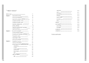
... PRESET AUTO MODE - AUTO PAN - EXIT 3-8 VIDEO SET MENU 3-9 - D-ZOOM - MOTION DET 3-7 - WHITE BAL - Front 1-7 Locations of Controls - PATTERN ALARM SET OTHER SET 3-10 3-11 3-12 3-14 3-15 3-15 3-15 3-16 3-18 3-18 3-20 3-21 3-23 Product specifications Table of contents " Before Usage 1-1 Chapter 1 SCC-641(P) Overview 1-5 SCC-641(P) Introduction 1-6 SCC-641(P) Location of Controls 1-7 Locations of Controls - Back 1-8 ADATER CONNECTION 1-9 INITIAL SETTING 1-10 Setting RS-422A/RS-485 Termination 1-11 SWITCH SETTING 1-12 Chapter 2 SCC-641...
... PRESET AUTO MODE - AUTO PAN - EXIT 3-8 VIDEO SET MENU 3-9 - D-ZOOM - MOTION DET 3-7 - WHITE BAL - Front 1-7 Locations of Controls - PATTERN ALARM SET OTHER SET 3-10 3-11 3-12 3-14 3-15 3-15 3-15 3-16 3-18 3-18 3-20 3-21 3-23 Product specifications Table of contents " Before Usage 1-1 Chapter 1 SCC-641(P) Overview 1-5 SCC-641(P) Introduction 1-6 SCC-641(P) Location of Controls 1-7 Locations of Controls - Back 1-8 ADATER CONNECTION 1-9 INITIAL SETTING 1-10 Setting RS-422A/RS-485 Termination 1-11 SWITCH SETTING 1-12 Chapter 2 SCC-641...
Owners Instructions
Page 5
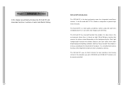
... be seen clearly even under bright-background lighting conditions and Auto Focus function that has all the important functions of security. The SCC-641(P) is a multifunction camera that enables it can catch clear images up to the movement of control and Switch Setting. It is a high quality surveillance camera using x22 zoom lens and digital zoom IC, it to focus according to 220 times. Chapter 1 SCC-641(P) Overview In this chapter we will...
... be seen clearly even under bright-background lighting conditions and Auto Focus function that has all the important functions of security. The SCC-641(P) is a multifunction camera that enables it can catch clear images up to the movement of control and Switch Setting. It is a high quality surveillance camera using x22 zoom lens and digital zoom IC, it to focus according to 220 times. Chapter 1 SCC-641(P) Overview In this chapter we will...
Owners Instructions
Page 7
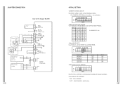
... DUPLEX is same as follows. Use number 3 PIN of SW501 to set as the following example: EX) CAMERA ADDR: When it's number 1, set BAUD RATE. " OFF " : HALF DUPLEX. (SSC-1000) ADAPTER CONNECTION SCC-641(P) Adapter BOARD INITIAL SETTING CAMERA ADDRESS SETUP Dip Switch setting is communication method with System Controller. A :SAMSUNG(SSC-1000) Setting BAUD RATE Use number 4 and 5 of SW501 to set communication Protocol. ON OFF SW500 Setting communication Protocol. " ON " : FULL DUPLEX. Use number 6~8 PIN of SW 501.
... DUPLEX is same as follows. Use number 3 PIN of SW501 to set as the following example: EX) CAMERA ADDR: When it's number 1, set BAUD RATE. " OFF " : HALF DUPLEX. (SSC-1000) ADAPTER CONNECTION SCC-641(P) Adapter BOARD INITIAL SETTING CAMERA ADDRESS SETUP Dip Switch setting is communication method with System Controller. A :SAMSUNG(SSC-1000) Setting BAUD RATE Use number 4 and 5 of SW501 to set communication Protocol. ON OFF SW500 Setting communication Protocol. " ON " : FULL DUPLEX. Use number 6~8 PIN of SW 501.
Owners Instructions
Page 11
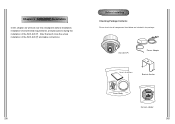
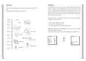
After that all components listed below are included in the package: SCC-641(P) Power Adapter Owner's Instructions Bracket Anchor Cover Body Camera Holder Before Installing Checking Package Contents Please check that we will look over the checkpoints before installation, installation environmental requirements, and precautions during the installation of the SCC-641(P) and cable connections. Chapter 2 SCC-641(P) Installation In this chapter we 'll show the actual installation of the SCC-641(P).
After that all components listed below are included in the package: SCC-641(P) Power Adapter Owner's Instructions Bracket Anchor Cover Body Camera Holder Before Installing Checking Package Contents Please check that we will look over the checkpoints before installation, installation environmental requirements, and precautions during the installation of the SCC-641(P) and cable connections. Chapter 2 SCC-641(P) Installation In this chapter we 'll show the actual installation of the SCC-641(P).
Owners Instructions
Page 12
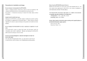
... or moisture or operate it becomes necessary to the product and handle and store properly. In case the dirt is a danger of the SCC-641(P) power supply system. Use with water, turn the power switch off immediately and contact a distributor. We strongly recommend that users avoid handling the interior part of electric shock. Avoid shaking or directly impacting the camera to prevent...
... or moisture or operate it becomes necessary to the product and handle and store properly. In case the dirt is a danger of the SCC-641(P) power supply system. Use with water, turn the power switch off immediately and contact a distributor. We strongly recommend that users avoid handling the interior part of electric shock. Avoid shaking or directly impacting the camera to prevent...
Owners Instructions
Page 13
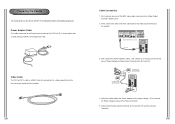
Video Cable The SCC-641(P)'s cable is shown below the Power Adapter to Power Input Terminal of the SCC-641(P). 4. Now connect the Power Adapter Cable. Connect the Remote Control Terminal of the BNC video cable connector to the Power Connector. 5. Power Adapter Cable The cable connected to the Power input terminal of the SCC-641(P) is a BNC Cable for connecting the video-output terminal to the Video Input Terminal of Power Adapter to the proper voltage. First, connect one part of the two lines of the monitor. 3. Adjust the switch below with...
Video Cable The SCC-641(P)'s cable is shown below the Power Adapter to Power Input Terminal of the SCC-641(P). 4. Now connect the Power Adapter Cable. Connect the Remote Control Terminal of the BNC video cable connector to the Power Connector. 5. Power Adapter Cable The cable connected to the Power input terminal of the SCC-641(P) is a BNC Cable for connecting the video-output terminal to the Video Input Terminal of Power Adapter to the proper voltage. First, connect one part of the two lines of the monitor. 3. Adjust the switch below with...
Owners Instructions
Page 14
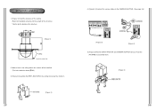
... the Length of ceiling Hole 2. SCC-641(P) Installation 1. [Figure 1] Install the structure on the ceiling and screw the 4 bolts in by the builder of the structure [Figure 1] Lenght of the structure) * Built in . [Figure 2] 4. [Figure 3,4] Connect the various cables to the CAMERA ADAPTER. (See page 2-6) [Figure 3] [Figure 4] 5. [Figure 5] Match the BRKT-ANCHOR and CAMERA ADAPTER and use 4screws (PH M4x8) to...
... the Length of ceiling Hole 2. SCC-641(P) Installation 1. [Figure 1] Install the structure on the ceiling and screw the 4 bolts in by the builder of the structure [Figure 1] Lenght of the structure) * Built in . [Figure 2] 4. [Figure 3,4] Connect the various cables to the CAMERA ADAPTER. (See page 2-6) [Figure 3] [Figure 4] 5. [Figure 5] Match the BRKT-ANCHOR and CAMERA ADAPTER and use 4screws (PH M4x8) to...
Owners Instructions
Page 15
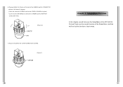
6. [Figure 6] Match the 3 holes on the back of the CAMERA and the CONNECTOR and turn it left about 15 degrees. (Check the sound of LOCKING and that the LEVER-LOCKING is in place) * Use the screws (BH M3XL8) to connect the CAMERA and the ADAPTER so they don't move. [Figure 6] 7. [Figure 7] Assemble the COVER-DOME onto the DOME. [Figure 7] Chapter 3 Setup Menu Overview In this chapter, we will look over the Setup Menu of the SCC-641(P), First we'll look over the overall structure of the Setup Menu, and then we'll look at the functions of each menu.
6. [Figure 6] Match the 3 holes on the back of the CAMERA and the CONNECTOR and turn it left about 15 degrees. (Check the sound of LOCKING and that the LEVER-LOCKING is in place) * Use the screws (BH M3XL8) to connect the CAMERA and the ADAPTER so they don't move. [Figure 6] 7. [Figure 7] Assemble the COVER-DOME onto the DOME. [Figure 7] Chapter 3 Setup Menu Overview In this chapter, we will look over the Setup Menu of the SCC-641(P), First we'll look over the overall structure of the Setup Menu, and then we'll look at the functions of each menu.
Owners Instructions
Page 17
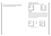
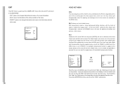
... be displayed on the connected monitor.On the CAMERA SET menu screen, select CAMERA ID to any desired location on the ID of the SCC-641(P). You will enable users of the Setup menu features will see the sub screen for deciding on the screen by using the LOCATION submenu. (CAMERA SET) CAMERA ID V-SYNC ZOOM SPEED MOTION DET ON... INT 3 OFF EXIT QUIT Press [Enter] * " ... RET SCC-641(P)... In this section, a description of the SCC-641...
... be displayed on the connected monitor.On the CAMERA SET menu screen, select CAMERA ID to any desired location on the ID of the SCC-641(P). You will enable users of the Setup menu features will see the sub screen for deciding on the screen by using the LOCATION submenu. (CAMERA SET) CAMERA ID V-SYNC ZOOM SPEED MOTION DET ON... INT 3 OFF EXIT QUIT Press [Enter] * " ... RET SCC-641(P)... In this section, a description of the SCC-641...
Owners Instructions
Page 18
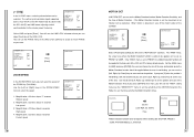
... the Motion Detection moves. The "AREA" menu, the screen area where the Motion Detection function is the INT mode made by clock inside the SCC-641(P) and LINE mode adjusting vertical synchronization to the basic part of the Controller. (CAMERA SET) CAMERA ID V-SYNC ZOOM SPEED MOTION DET OFF INT 3 ON.. The vertical synchronization signal supported by the SCC-641(P) is going to be applied to the exterior power frequency. (CAMERA SET) CAMERA ID V-SYNC ZOOM SPEED MOTION DET...
... the Motion Detection moves. The "AREA" menu, the screen area where the Motion Detection function is the INT mode made by clock inside the SCC-641(P) and LINE mode adjusting vertical synchronization to the basic part of the Controller. (CAMERA SET) CAMERA ID V-SYNC ZOOM SPEED MOTION DET OFF INT 3 ON.. The vertical synchronization signal supported by the SCC-641(P) is going to be applied to the exterior power frequency. (CAMERA SET) CAMERA ID V-SYNC ZOOM SPEED MOTION DET...
Owners Instructions
Page 19
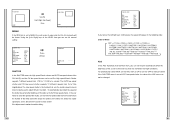
... function. (VIDEO SET) IRIS SHUTTER AGC WHITE BAL SPECIAL AUTO FOCUS D-ZOOM EXIT ALC... In the SCC-641(P), setting the BLC (Back Light Compensation), submenu of ALC/MANU menu, will exit the "AREA" setting menu. QUIT: Ignores the changed information and restores the initial factory defaults of the menu. (CAMERA SET) CAMERA ID V-SYNC ZOOM SPEED MOTION DET OFF INT 3 OFF EXIT QUIT VIDEO SET MENU IRIS The video output level of the monitor can be controlled by the IRIS lens depending...
... function. (VIDEO SET) IRIS SHUTTER AGC WHITE BAL SPECIAL AUTO FOCUS D-ZOOM EXIT ALC... In the SCC-641(P), setting the BLC (Back Light Compensation), submenu of ALC/MANU menu, will exit the "AREA" setting menu. QUIT: Ignores the changed information and restores the initial factory defaults of the menu. (CAMERA SET) CAMERA ID V-SYNC ZOOM SPEED MOTION DET OFF INT 3 OFF EXIT QUIT VIDEO SET MENU IRIS The video output level of the monitor can be controlled by the IRIS lens depending...
Owners Instructions
Page 20
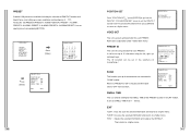
.... If the user wants to OFF for manual control. SHUTTER In the SHUTTER menu, the high-speed Electric shutter and AUTO low speed shutter of the SCC-641(P) and the FIX low speed shutter can set it to select the speed of the shutter, set Iris manual setting. (VIDEO SET) IRIS SHUTTER AGC WHITE BAL SPECIAL AUTO FOCUS D-ZOOM EXIT MANU... The AUTO low speed shutter and FIX low speed shutter supports 12 different speeds from...
.... If the user wants to OFF for manual control. SHUTTER In the SHUTTER menu, the high-speed Electric shutter and AUTO low speed shutter of the SCC-641(P) and the FIX low speed shutter can set it to select the speed of the shutter, set Iris manual setting. (VIDEO SET) IRIS SHUTTER AGC WHITE BAL SPECIAL AUTO FOCUS D-ZOOM EXIT MANU... The AUTO low speed shutter and FIX low speed shutter supports 12 different speeds from...
Owners Instructions
Page 21
... MANU... User : Set the appropriate value in the PRESET menu. (VIDEO SET) IRIS SHUTTER AGC WHITE BAL SPECIAL AUTO FOCUS D-ZOOM EXIT ALC... MANU: Select MANU item and press [ENTER], the sub screen where you can set the white Balance considering the current illumination. - 3200 K : Set color temperature to 3200 K - 5600 K : Set color temperature to MANUAL mode, the user can select manual White Balance will automatically set to 5600 K - The general light color temperatures are...
... MANU... User : Set the appropriate value in the PRESET menu. (VIDEO SET) IRIS SHUTTER AGC WHITE BAL SPECIAL AUTO FOCUS D-ZOOM EXIT ALC... MANU: Select MANU item and press [ENTER], the sub screen where you can set the white Balance considering the current illumination. - 3200 K : Set color temperature to 3200 K - 5600 K : Set color temperature to MANUAL mode, the user can select manual White Balance will automatically set to 5600 K - The general light color temperatures are...
Owners Instructions
Page 22
... Digital Zoom is not necessary. - MF: In MANUAL FOCUS MODE the user adjusts the Focus manually. - OFF ON ATW OFF AF OFF QUIT D-ZOOM In the D-ZOOM menu you can monitor the screen continuously and it 's moving /stopping. OFF ON ATW OFF AF X10 QUIT EXIT It's the same as AF mode. POSI/NEGA: Video output signal is the Optic Zoom for 22 times the size so the camera can...
... Digital Zoom is not necessary. - MF: In MANUAL FOCUS MODE the user adjusts the Focus manually. - OFF ON ATW OFF AF OFF QUIT D-ZOOM In the D-ZOOM menu you can monitor the screen continuously and it 's moving /stopping. OFF ON ATW OFF AF X10 QUIT EXIT It's the same as AF mode. POSI/NEGA: Video output signal is the Optic Zoom for 22 times the size so the camera can...
Owners Instructions
Page 23
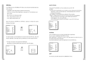
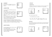
... screen conditions and monitoring. (0 ~ 127) Among the 128 PRESETS PRESET 0: HOME POSITION, PRESET 1: ALARM1, PRESET 2: ALARM2, PRESET 3: ALARM3, PRESET 4: ALARM4,PRESET 5: set up for the DWELL TIME of the PRESET location in "SCAN" motion. PRESET... VIDEO SET ON... Then returns to a higher menu. AUTO MODE... SCAN ON DWELL TIME 2S EXIT QUIT POSITION SET From "POSITION SET " press [ENTER] to get into the PAN/TILT, FOCUS/ZOOM SET screen to set DWELL TIME From 1 ~ 60 Sec. "DEL" : Deletes the selected information and restores the DEFAULT. RET PRESET 0.... PRESET...
... screen conditions and monitoring. (0 ~ 127) Among the 128 PRESETS PRESET 0: HOME POSITION, PRESET 1: ALARM1, PRESET 2: ALARM2, PRESET 3: ALARM3, PRESET 4: ALARM4,PRESET 5: set up for the DWELL TIME of the PRESET location in "SCAN" motion. PRESET... VIDEO SET ON... Then returns to a higher menu. AUTO MODE... SCAN ON DWELL TIME 2S EXIT QUIT POSITION SET From "POSITION SET " press [ENTER] to get into the PAN/TILT, FOCUS/ZOOM SET screen to set DWELL TIME From 1 ~ 60 Sec. "DEL" : Deletes the selected information and restores the DEFAULT. RET PRESET 0.... PRESET...
Owners Instructions
Page 24
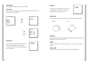
.... ALARM SET... Adjust PAN/TILT location and press [ENTER] to return to END location (PAN location standard) "RIGHT " : "LEFT " : ENDLESS This is a setting function for setting up SPEED. ** MAIN MENU ** CAMERA... RET Press [Enter] AUTO PAN START SET ... get into the END SET setup screen by pressing [ENTER]. It can be set to higher menu. SPEED This is a 360-degree rotation function that only stops for the DWELL TIME in AUTO MODE. DIRECTION...
.... ALARM SET... Adjust PAN/TILT location and press [ENTER] to return to END location (PAN location standard) "RIGHT " : "LEFT " : ENDLESS This is a setting function for setting up SPEED. ** MAIN MENU ** CAMERA... RET Press [Enter] AUTO PAN START SET ... get into the END SET setup screen by pressing [ENTER]. It can be set to higher menu. SPEED This is a 360-degree rotation function that only stops for the DWELL TIME in AUTO MODE. DIRECTION...
Owners Instructions
Page 25
... for a time and each ALARM movement time is decided depending on the features of the PRESET and PATTERN connected. ** MAIN MENU ** CAMERA... ALARM IN SET.. ALARM IN SET Set the TYPE to the DWELL TIME of the SENSOR connected. ALARM SET... Press [Enter] (AUTO MODE) AUTO PAN ... VIDEO SET... PRESET ... Press [Enter] ( ALARM SET) ALARM PRIORITY SET.. AUX OUT CONTROL.. OTHER SET... It recognizes the ALARM signal input as PAN, TILT, ZOOM, and FOCUS are played for 30 seconds, it memorizes the MANUAL movements and...
... for a time and each ALARM movement time is decided depending on the features of the PRESET and PATTERN connected. ** MAIN MENU ** CAMERA... ALARM IN SET.. ALARM IN SET Set the TYPE to the DWELL TIME of the SENSOR connected. ALARM SET... Press [Enter] (AUTO MODE) AUTO PAN ... VIDEO SET... PRESET ... Press [Enter] ( ALARM SET) ALARM PRIORITY SET.. AUX OUT CONTROL.. OTHER SET... It recognizes the ALARM signal input as PAN, TILT, ZOOM, and FOCUS are played for 30 seconds, it memorizes the MANUAL movements and...
Owners Instructions
Page 26
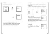
... FULL PATTERN 1+PATTERN2+PATTERN3. PRESET... AUTO MODE... VIDEO SET... OTHER SET... OTHER SET... The HOME location is set to the HOME location automatically. ALARM SET... ALARM SET... ALARM OUT Each ALARM input corresponds to the 90 limit using the Joystick, the camera PAN automatically revolves 180 showing the opposite area of the Tilt area.It gives the effect of extending the Tilt operating area 180 . ** MAIN MENU ** CAMERA... When the ALARM is inputted the correspondence...
... FULL PATTERN 1+PATTERN2+PATTERN3. PRESET... AUTO MODE... VIDEO SET... OTHER SET... OTHER SET... The HOME location is set to the HOME location automatically. ALARM SET... ALARM SET... ALARM OUT Each ALARM input corresponds to the 90 limit using the Joystick, the camera PAN automatically revolves 180 showing the opposite area of the Tilt area.It gives the effect of extending the Tilt operating area 180 . ** MAIN MENU ** CAMERA... When the ALARM is inputted the correspondence...
Owners Instructions
Page 27
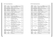
...COMBI DOME CAMERA - Object Illumination Color Temperature Signal Output Lens PAN Function TILT Function REMOTE CONTROL ALARM Operation Temperature Operation Humidity SIZE Weight Altitude Contents - one body; 22X Zoom lens - DOME : 147 ( ), Outline : 159.5( - 2Kg - 3,000M or less ) x 176(H)(Adapter:23.5(H)mm SCC-641P Product Specifications Items Product Type Power Input Power Consumption Broadcasting Type Image Device Effective Pixels Scanning Mode Scanning line Frequency Synchronization Mode Resolution S/N Ratio Min. Preset Pan Speed : 240 /sec, maximum - Manual Tilt Speed...
...COMBI DOME CAMERA - Object Illumination Color Temperature Signal Output Lens PAN Function TILT Function REMOTE CONTROL ALARM Operation Temperature Operation Humidity SIZE Weight Altitude Contents - one body; 22X Zoom lens - DOME : 147 ( ), Outline : 159.5( - 2Kg - 3,000M or less ) x 176(H)(Adapter:23.5(H)mm SCC-641P Product Specifications Items Product Type Power Input Power Consumption Broadcasting Type Image Device Effective Pixels Scanning Mode Scanning line Frequency Synchronization Mode Resolution S/N Ratio Min. Preset Pan Speed : 240 /sec, maximum - Manual Tilt Speed...


