Owners Instructions
Page 1
Combi Dome Camera SCC-641(P) Owner s Instructions Part : AB68-00136A Printed in Korea
Combi Dome Camera SCC-641(P) Owner s Instructions Part : AB68-00136A Printed in Korea
Owners Instructions
Page 2
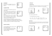
... user who has used similar cameras before to the general user to read from a simple introduction of the control locations and functions of the SCC-641(P) in the SCC-641(P) would be the SCC-641(P) Setup Menu. "Chapter2 SCC-641(P) Installation" explains the installation procedures of the SCC-641(P), part names and functions, and Switching Settings. The SCC-641(P) Setup Menu is explained...
... user who has used similar cameras before to the general user to read from a simple introduction of the control locations and functions of the SCC-641(P) in the SCC-641(P) would be the SCC-641(P) Setup Menu. "Chapter2 SCC-641(P) Installation" explains the installation procedures of the SCC-641(P), part names and functions, and Switching Settings. The SCC-641(P) Setup Menu is explained...
Owners Instructions
Page 4
... of CAMERA Block Menu 3-5 - SPECIAL - Back 1-8 ADATER CONNECTION 1-9 INITIAL SETTING 1-10 Setting RS-422A/RS-485 Termination 1-11 SWITCH SETTING 1-12 Chapter 2 SCC-641(P) Installations 2-1 Checking Package Contents 2-2 Precautions for Installation and Usage 2-3 Preparing the Cable 2-5 Connecting the Cable 2-6 SCC-641(P) Installation 2-7 Chapter 3 Setup Menu Overview 3-1 Contents of Setup Menu 3-2 General Structure of Controls - ZOOM SPEED 3-6 - D-ZOOM...
... of CAMERA Block Menu 3-5 - SPECIAL - Back 1-8 ADATER CONNECTION 1-9 INITIAL SETTING 1-10 Setting RS-422A/RS-485 Termination 1-11 SWITCH SETTING 1-12 Chapter 2 SCC-641(P) Installations 2-1 Checking Package Contents 2-2 Precautions for Installation and Usage 2-3 Preparing the Cable 2-5 Connecting the Cable 2-6 SCC-641(P) Installation 2-7 Chapter 3 Setup Menu Overview 3-1 Contents of Setup Menu 3-2 General Structure of Controls - ZOOM SPEED 3-6 - D-ZOOM...
Owners Instructions
Page 5
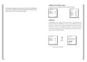
It can be remote controlled. SCC-641(P) Introduction The SCC-641(P) is a multifunction camera that has all the important functions of the object. It is the best performing zoom lens integrated surveillance camera. The SCC-641(P) is almost no light, White Balance function that corrects the picture ...high quality surveillance camera using x22 zoom lens and digital zoom IC, it to focus according to the movement of other surveillance cameras. The SCC-641(P) uses an Alarm function for alert situations and moving camera in banks or companies to 220 times. The SCC-641(P) has Low...
It can be remote controlled. SCC-641(P) Introduction The SCC-641(P) is a multifunction camera that has all the important functions of the object. It is the best performing zoom lens integrated surveillance camera. The SCC-641(P) is almost no light, White Balance function that corrects the picture ...high quality surveillance camera using x22 zoom lens and digital zoom IC, it to focus according to the movement of other surveillance cameras. The SCC-641(P) uses an Alarm function for alert situations and moving camera in banks or companies to 220 times. The SCC-641(P) has Low...
Owners Instructions
Page 7
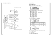
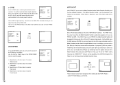
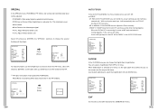
A :SAMSUNG(SSC-1000) Setting BAUD RATE Use number 4 and 5 of SW501 to set communication Protocol. " OFF " : HALF DUPLEX. (SSC-1000) ADAPTER CONNECTION SCC-641(P) Adapter BOARD INITIAL SETTING CAMERA ADDRESS SETUP Dip Switch setting is communication method with System Controller. Use number 6~8 PIN of SW 501. ON OFF ... ON OFF OFF Setting HALF or FULL DUPLEX 12 3 4 5 6 ON OFF SW501 7 8 HALF or FULL DUPLEX is same as the following example: EX) CAMERA ADDR: When it's number 1, set BAUD RATE. Use number 3 PIN of SW501 to set as follows. " ON " : FULL DUPLEX. ON OFF SW500 Setting...
A :SAMSUNG(SSC-1000) Setting BAUD RATE Use number 4 and 5 of SW501 to set communication Protocol. " OFF " : HALF DUPLEX. (SSC-1000) ADAPTER CONNECTION SCC-641(P) Adapter BOARD INITIAL SETTING CAMERA ADDRESS SETUP Dip Switch setting is communication method with System Controller. Use number 6~8 PIN of SW 501. ON OFF ... ON OFF OFF Setting HALF or FULL DUPLEX 12 3 4 5 6 ON OFF SW501 7 8 HALF or FULL DUPLEX is same as the following example: EX) CAMERA ADDR: When it's number 1, set BAUD RATE. Use number 3 PIN of SW501 to set as follows. " ON " : FULL DUPLEX. ON OFF SW500 Setting...
Owners Instructions
Page 8
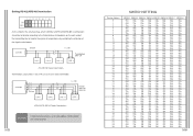
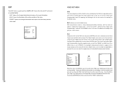
... Termination: using numbers 1 and 2 PIN, turn to ON and it should be terminated. Division n < 128 Division SW1-ON SW2-ON CAUTION If more than one camera is connected it will be terminated according to the Cable feature of impedance on the each end of the transmitting line to transfer the signals...
... Termination: using numbers 1 and 2 PIN, turn to ON and it should be terminated. Division n < 128 Division SW1-ON SW2-ON CAUTION If more than one camera is connected it will be terminated according to the Cable feature of impedance on the each end of the transmitting line to transfer the signals...
Owners Instructions
Page 11
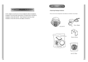
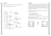
Before Installing Checking Package Contents Please check that we will look over the checkpoints before installation, installation environmental requirements, and precautions during the installation of the SCC-641(P) and cable connections. After that all components listed below are included in the package: SCC-641(P) Power Adapter Owner's Instructions Bracket Anchor Cover Body Camera Holder Chapter 2 SCC-641(P) Installation In this chapter we 'll show the actual installation of the SCC-641(P).
Before Installing Checking Package Contents Please check that we will look over the checkpoints before installation, installation environmental requirements, and precautions during the installation of the SCC-641(P) and cable connections. After that all components listed below are included in the package: SCC-641(P) Power Adapter Owner's Instructions Bracket Anchor Cover Body Camera Holder Chapter 2 SCC-641(P) Installation In this chapter we 'll show the actual installation of the SCC-641(P).
Owners Instructions
Page 12
... properly. There is in a stable environment. Moisture can damage the SCC-641(P) and increases the danger of the SCC-641(P). Avoid shaking or directly impacting the camera to prevent damage to rain or moisture or operate it becomes necessary to disassemble the SCC-641(P). Handle the SCC-641(P) with water, turn the power switch off immediately and contact a distributor...
... properly. There is in a stable environment. Moisture can damage the SCC-641(P) and increases the danger of the SCC-641(P). Avoid shaking or directly impacting the camera to prevent damage to rain or moisture or operate it becomes necessary to disassemble the SCC-641(P). Handle the SCC-641(P) with water, turn the power switch off immediately and contact a distributor...
Owners Instructions
Page 14
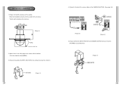
...-ANCHOR on the ceiling. (Refer to assemble them. [Figure 5] SCC-641(P) Installation 1. [Figure 1] Install the structure on the ceiling and screw the 4 bolts in. [Figure 2] 4. [Figure 3,4] Connect the various cables to the CAMERA ADAPTER. (See page 2-6) [Figure 3] [Figure 4] 5. [Figure 5] Match the BRKT-ANCHOR and CAMERA ADAPTER and use 4screws (PH M4x8) to Installation reference...
...-ANCHOR on the ceiling. (Refer to assemble them. [Figure 5] SCC-641(P) Installation 1. [Figure 1] Install the structure on the ceiling and screw the 4 bolts in. [Figure 2] 4. [Figure 3,4] Connect the various cables to the CAMERA ADAPTER. (See page 2-6) [Figure 3] [Figure 4] 5. [Figure 5] Match the BRKT-ANCHOR and CAMERA ADAPTER and use 4screws (PH M4x8) to Installation reference...
Owners Instructions
Page 15
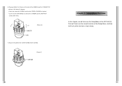
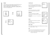
6. [Figure 6] Match the 3 holes on the back of the CAMERA and the CONNECTOR and turn it left about 15 degrees. (Check the sound of LOCKING and that the LEVER-LOCKING is in place) * Use the screws (BH M3XL8) to connect the CAMERA and the ADAPTER so they don't move. [Figure 6] 7. [Figure 7] Assemble the COVER-DOME onto the DOME. [Figure 7] Chapter 3 Setup Menu Overview In this chapter, we will look over the Setup Menu of the SCC-641(P), First we'll look over the overall structure of the Setup Menu, and then we'll look at the functions of each menu.
6. [Figure 6] Match the 3 holes on the back of the CAMERA and the CONNECTOR and turn it left about 15 degrees. (Check the sound of LOCKING and that the LEVER-LOCKING is in place) * Use the screws (BH M3XL8) to connect the CAMERA and the ADAPTER so they don't move. [Figure 6] 7. [Figure 7] Assemble the COVER-DOME onto the DOME. [Figure 7] Chapter 3 Setup Menu Overview In this chapter, we will look over the Setup Menu of the SCC-641(P), First we'll look over the overall structure of the Setup Menu, and then we'll look at the functions of each menu.
Owners Instructions
Page 16
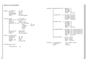
SPECIAL ON.../OFF POSI/NEGA PIP MIRROR H-DTL V-DTL RET + / - ON.../OFF ON/OFF AUTO FOCUS D-ZOOM EXIT AF/MF/ONEAF OFF/ X2 ~ X10 QUIT/SAVE/PRESET PRESET POSITION SET VIDEO SET PRESET ID SCAN DWELL TIME EXIT ON.../OFF ON.../OFF .../1~ 60MIN/2~12HOUR ON/OFF QUIT/SAVE SHUTTER OFF/1/100~1OK,AUTO/FIX AGC ON/OFF WHITE BAL ATW/AWC/MANU... Structure of the Setup Menu CAMERA CAMERA ID V-SYNC ZOOM SPEED MOTION DET EXIT ON.../OFF INT/LINE... 1/2/3/4 ON.../OFF QUIT/SAVE/PRESET VIDEO SET IRIS ALC.../MANU...
SPECIAL ON.../OFF POSI/NEGA PIP MIRROR H-DTL V-DTL RET + / - ON.../OFF ON/OFF AUTO FOCUS D-ZOOM EXIT AF/MF/ONEAF OFF/ X2 ~ X10 QUIT/SAVE/PRESET PRESET POSITION SET VIDEO SET PRESET ID SCAN DWELL TIME EXIT ON.../OFF ON.../OFF .../1~ 60MIN/2~12HOUR ON/OFF QUIT/SAVE SHUTTER OFF/1/100~1OK,AUTO/FIX AGC ON/OFF WHITE BAL ATW/AWC/MANU... Structure of the Setup Menu CAMERA CAMERA ID V-SYNC ZOOM SPEED MOTION DET EXIT ON.../OFF INT/LINE... 1/2/3/4 ON.../OFF QUIT/SAVE/PRESET VIDEO SET IRIS ALC.../MANU...
Owners Instructions
Page 17
... R S T U V W X YZ0 1 2 3 4 5 6 7 8 9 : ! - + ()/ SP SP LOCATION... RET SCC-641(P)... In this section, a description of the SCC-641(P) to tailor it to their personal needs. You will enable users of the Setup menu features will see the sub screen for deciding on the screen by using the LOCATION submenu. (CAMERA SET) CAMERA ID V-SYNC ZOOM SPEED MOTION DET ON... The...
... R S T U V W X YZ0 1 2 3 4 5 6 7 8 9 : ! - + ()/ SP SP LOCATION... RET SCC-641(P)... In this section, a description of the SCC-641(P) to tailor it to their personal needs. You will enable users of the Setup menu features will see the sub screen for deciding on the screen by using the LOCATION submenu. (CAMERA SET) CAMERA ID V-SYNC ZOOM SPEED MOTION DET ON... The...
Owners Instructions
Page 18
.... The "AREA" menu, the screen area where the Motion Detection function is not blinking, you can use the PHASE menu of the SCC-641(P)'s factory default presets. If the "AREA" menu is set the size of the MOTION Detection.The Higher it sets off the Alarm signal... Detection function, Motion Detection Sensitivity, and the Area of the ZOOM Key (Tele/Wide). The vertical synchronization signal supported by the SCC-641(P) is set, the more , you will start to the exterior power frequency. (CAMERA SET) CAMERA ID V-SYNC ZOOM SPEED MOTION DET OFF INT 3 OFF EXIT QUIT Select LINE...
.... The "AREA" menu, the screen area where the Motion Detection function is not blinking, you can use the PHASE menu of the SCC-641(P)'s factory default presets. If the "AREA" menu is set the size of the MOTION Detection.The Higher it sets off the Alarm signal... Detection function, Motion Detection Sensitivity, and the Area of the ZOOM Key (Tele/Wide). The vertical synchronization signal supported by the SCC-641(P) is set, the more , you will start to the exterior power frequency. (CAMERA SET) CAMERA ID V-SYNC ZOOM SPEED MOTION DET OFF INT 3 OFF EXIT QUIT Select LINE...
Owners Instructions
Page 19
... is set to PRESET, the backlight compensation function is applied to the factory defaults of the SCC-641(P).If the AREA menu is set to USER and [ENTER] is used to quit the CAMERA SET menu of the SCC-641(P) and return to the MAIN MENU. - OFF ---- ---- If you press [5] when the position is not... to set the position and size of the menu. - QUIT: Ignores the changed information and restores the initial factory defaults of the menu. (CAMERA SET) CAMERA ID V-SYNC ZOOM SPEED MOTION DET OFF INT 3 OFF EXIT QUIT VIDEO SET MENU IRIS The video output level of the monitor can be controlled by the...
... is set to PRESET, the backlight compensation function is applied to the factory defaults of the SCC-641(P).If the AREA menu is set to USER and [ENTER] is used to quit the CAMERA SET menu of the SCC-641(P) and return to the MAIN MENU. - OFF ---- ---- If you press [5] when the position is not... to set the position and size of the menu. - QUIT: Ignores the changed information and restores the initial factory defaults of the menu. (CAMERA SET) CAMERA ID V-SYNC ZOOM SPEED MOTION DET OFF INT 3 OFF EXIT QUIT VIDEO SET MENU IRIS The video output level of the monitor can be controlled by the...
Owners Instructions
Page 21
... the color temperature only one time. User : Set the appropriate value in the PRESET menu. (VIDEO SET) IRIS SHUTTER AGC WHITE BAL SPECIAL AUTO FOCUS D-ZOOM EXIT ALC... RED (00) ---- ---BLUE (00) ---- ---RET When the WHITE BAL menu is set the white Balance considering the current illumination. - 3200 ... [ENTER] while having a white paper in Kelvin ( K) units. Use the left/right keys to the color temperature.In the case of the Camera will be shown. OFF AF OFF QUIT Press [Enter] (AWB/MANU) PRESET OFF(USER)... The general light color temperatures are generally denoted as color...
... the color temperature only one time. User : Set the appropriate value in the PRESET menu. (VIDEO SET) IRIS SHUTTER AGC WHITE BAL SPECIAL AUTO FOCUS D-ZOOM EXIT ALC... RED (00) ---- ---BLUE (00) ---- ---RET When the WHITE BAL menu is set the white Balance considering the current illumination. - 3200 ... [ENTER] while having a white paper in Kelvin ( K) units. Use the left/right keys to the color temperature.In the case of the Camera will be shown. OFF AF OFF QUIT Press [Enter] (AWB/MANU) PRESET OFF(USER)... The general light color temperatures are generally denoted as color...
Owners Instructions
Page 22
... AUTO FOCUS MODE, you can film at up , down] keys to set to AF, MF, or ONEAF. - ONEAF: In ONEAF mode the SCC-641(P) auto focuses only while moving the zoom keys, it will be adjusted. - OFF ON ATW OFF AF X10 QUIT EXIT It's the same as AF mode. Select ON and... press [ENTER], the "SPECIAL" submenu to choose the special functions will automatically focus so FOCUS key input is the Optic Zoom for 22 times the size so the camera can choose the Digital Zoom magnification. Use the left /right keys to select an item.In the PIP menu, select ON and press [ENTER...
... AUTO FOCUS MODE, you can film at up , down] keys to set to AF, MF, or ONEAF. - ONEAF: In ONEAF mode the SCC-641(P) auto focuses only while moving the zoom keys, it will be adjusted. - OFF ON ATW OFF AF X10 QUIT EXIT It's the same as AF mode. Select ON and... press [ENTER], the "SPECIAL" submenu to choose the special functions will automatically focus so FOCUS key input is the Optic Zoom for 22 times the size so the camera can choose the Digital Zoom magnification. Use the left /right keys to select an item.In the PIP menu, select ON and press [ENTER...
Owners Instructions
Page 23
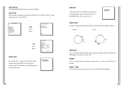
...to "OFF" no movement in "SCAN" motion. PRESET... The ID location can be set the PAN/TILT location and FOCUS/ZOOM condition then press [ENTER] to return to a higher menu. RET PRESET 0.... PRESET NO.0 POSITION SET... ON... VIDEO ...MODE... PRESET ID This is a function setting for each PRESET. It can be set in the submenu of PAN/TILT location and Zoom/Focus, and setting up screen conditions and monitoring. (0 ~ 127) Among the 128 PRESETS PRESET 0: HOME POSITION, PRESET 1: ALARM1...is the ID set as special preset corresponding MOTION. ** MAIN MENU ** CAMERA...
...to "OFF" no movement in "SCAN" motion. PRESET... The ID location can be set the PAN/TILT location and FOCUS/ZOOM condition then press [ENTER] to return to a higher menu. RET PRESET 0.... PRESET NO.0 POSITION SET... ON... VIDEO ...MODE... PRESET ID This is a function setting for each PRESET. It can be set in the submenu of PAN/TILT location and Zoom/Focus, and setting up screen conditions and monitoring. (0 ~ 127) Among the 128 PRESETS PRESET 0: HOME POSITION, PRESET 1: ALARM1...is the ID set as special preset corresponding MOTION. ** MAIN MENU ** CAMERA...
Owners Instructions
Page 24
... START to END location (PAN location standard) "RIGHT " : "LEFT " : ENDLESS This is a 360-degree rotation function that only stops for setting up SPEED. ** MAIN MENU ** CAMERA... Adjust PAN/TILT location and press [ENTER] to return to higher menu.
... START to END location (PAN location standard) "RIGHT " : "LEFT " : ENDLESS This is a 360-degree rotation function that only stops for setting up SPEED. ** MAIN MENU ** CAMERA... Adjust PAN/TILT location and press [ENTER] to return to higher menu.
Owners Instructions
Page 25
...), "NC" (Normal Close), or "OFF" depending on it's correspondence to the DWELL TIME of the PRESET and PATTERN connected. ** MAIN MENU ** CAMERA... ALARM IN SET.. ALARM PATTERN SET.. ALARM IN SET Set the TYPE to finish set up before the 30-second ends, press [ENTER]. PRESET... OTHER... INPUTs and 3 ALARM OUTs.It can be set to a higher menu. It recognizes the ALARM signal input as PAN, TILT, ZOOM, and FOCUS are played for 30 seconds. ** MAIN MENU ** CAMERA... PRESET ... AUTO MODE... ALARM SET... Press [Enter] ( ALARM SET) ALARM PRIORITY SET.. ALARM OUT SET.. AUX OUT CONTROL...
...), "NC" (Normal Close), or "OFF" depending on it's correspondence to the DWELL TIME of the PRESET and PATTERN connected. ** MAIN MENU ** CAMERA... ALARM IN SET.. ALARM PATTERN SET.. ALARM IN SET Set the TYPE to finish set up before the 30-second ends, press [ENTER]. PRESET... OTHER... INPUTs and 3 ALARM OUTs.It can be set to a higher menu. It recognizes the ALARM signal input as PAN, TILT, ZOOM, and FOCUS are played for 30 seconds. ** MAIN MENU ** CAMERA... PRESET ... AUTO MODE... ALARM SET... Press [Enter] ( ALARM SET) ALARM PRIORITY SET.. ALARM OUT SET.. AUX OUT CONTROL...
Owners Instructions
Page 26
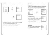
... ALARM4 MOTION OFF OFF 1 2 3 EXIT QUIT The OFF in the PRESET location corresponding the ALARM for a certain time, the camera moves to the HOME location automatically. PRESET... When the ALARM is inputted the correspondence will always operate regardless of the ALARM. ALARM ... 1 + PATTERN 2, continuous motion of HALF 2 Pattern 2 + PATTERN 3 and continuous motion of extending the Tilt operating area 180 . ** MAIN MENU ** CAMERA... AUX OUT CONTROL OUT1 OUT2 OUT3 OFF OFF ON EXIT QUIT OTHER SET HOME RETURN When there is working . ALARM SET... OTHER SET... ALARM SET...
... ALARM4 MOTION OFF OFF 1 2 3 EXIT QUIT The OFF in the PRESET location corresponding the ALARM for a certain time, the camera moves to the HOME location automatically. PRESET... When the ALARM is inputted the correspondence will always operate regardless of the ALARM. ALARM ... 1 + PATTERN 2, continuous motion of HALF 2 Pattern 2 + PATTERN 3 and continuous motion of extending the Tilt operating area 180 . ** MAIN MENU ** CAMERA... AUX OUT CONTROL OUT1 OUT2 OUT3 OFF OFF ON EXIT QUIT OTHER SET HOME RETURN When there is working . ALARM SET... OTHER SET... ALARM SET...


