Open Source Guide (ENGLISH)
Page 1
... source or binary form) with a work based on the Program) on each file should have at no warranty for this section has the sole purpose of protecting the integrity of software generally. ❑ NO WARRANTY 11. If identifiable sections of any part thereof, to be licensed as a special exception, the source code distributed need to make certain that everyone understands that component...
... source or binary form) with a work based on the Program) on each file should have at no warranty for this section has the sole purpose of protecting the integrity of software generally. ❑ NO WARRANTY 11. If identifiable sections of any part thereof, to be licensed as a special exception, the source code distributed need to make certain that everyone understands that component...
Open Source Guide (ENGLISH)
Page 2
...the terms of the ordinary General Public License). 16. You can redistribute and change. IN NO EVENT UNLESS REQUIRED BY APPLICABLE LAW OR AGREED TO IN WRITING WILL...USE OR INABILITY TO USE THE LIBRARY (INCLUDING BUT NOT LIMITED TO LOSS OF DATA OR DATA BEING RENDERED INACCURATE OR LOSSES SUSTAINED BY YOU OR THIRD PARTIES OR A FAILURE OF THE LIBRARY TO OPERATE WITH ANY OTHER SOFTWARE...want it free software that everyone can do so by permitting redistribution under these terms, attach the following notices to the public, we recommend making it to be of warranty; and each source file to ...
...the terms of the ordinary General Public License). 16. You can redistribute and change. IN NO EVENT UNLESS REQUIRED BY APPLICABLE LAW OR AGREED TO IN WRITING WILL...USE OR INABILITY TO USE THE LIBRARY (INCLUDING BUT NOT LIMITED TO LOSS OF DATA OR DATA BEING RENDERED INACCURATE OR LOSSES SUSTAINED BY YOU OR THIRD PARTIES OR A FAILURE OF THE LIBRARY TO OPERATE WITH ANY OTHER SOFTWARE...want it free software that everyone can do so by permitting redistribution under these terms, attach the following notices to the public, we recommend making it to be of warranty; and each source file to ...
User Manual (ENGLISH)
Page 3
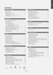
... Installing the Wall Mount Kit (LN-S3251D/LN-S3252D/LN-S4051D/LN-S4052D 59 Using the Anti-Theft Kensington Lock 60 Specifications 60 Symbol Press Important Note One-Touch Button English-1 Digital .. 46 Menu Transparency Level 47 Using the Energy Saving Feature 47 Setting the Function Help 48 Using the V-Chip 48 How to the Sound of Features 2 Accessories 2 Viewing the Control Panel 3 Viewing the Connection Panel 4 Remote Control 6 Installing Batteries in the Remote Control 7 CONNECTIONS Connecting VHF and UHF Antennas 7 Connecting Cable TV 8 Connecting a VCR 9 Connecting...
... Installing the Wall Mount Kit (LN-S3251D/LN-S3252D/LN-S4051D/LN-S4052D 59 Using the Anti-Theft Kensington Lock 60 Specifications 60 Symbol Press Important Note One-Touch Button English-1 Digital .. 46 Menu Transparency Level 47 Using the Energy Saving Feature 47 Setting the Function Help 48 Using the V-Chip 48 How to the Sound of Features 2 Accessories 2 Viewing the Control Panel 3 Viewing the Connection Panel 4 Remote Control 6 Installing Batteries in the Remote Control 7 CONNECTIONS Connecting VHF and UHF Antennas 7 Connecting Cable TV 8 Connecting a VCR 9 Connecting...
User Manual (ENGLISH)
Page 4
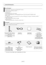
... Stand LN-S2651D (BN96-03358B) LN-S2652D (BN96-03358A) LN-S3251D (BN96-02998A) LN-S3252D (BN96-02998B) Screw LN-S2651D/LN-S3251D (6002-001294) LN-S2652D/LN-S3252D (6003-001324) Owner's Instructions The items color and shape may vary depending on and off. A special sleep timer. Remote Control The supplied remote can be used to turn the TV on the model. Excellent Picture Quality - If any items are included with no Set-Top Box needed. General Information List of Features Adjustable picture settings...
... Stand LN-S2651D (BN96-03358B) LN-S2652D (BN96-03358A) LN-S3251D (BN96-02998A) LN-S3252D (BN96-02998B) Screw LN-S2651D/LN-S3251D (6002-001294) LN-S2652D/LN-S3252D (6003-001324) Owner's Instructions The items color and shape may vary depending on and off. A special sleep timer. Remote Control The supplied remote can be used to turn the TV on the model. Excellent Picture Quality - If any items are included with no Set-Top Box needed. General Information List of Features Adjustable picture settings...
User Manual (ENGLISH)
Page 5
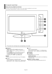
.... Viewing the Control Panel Buttons on the Lower-Right Part of your TV's basic features, including the on-screen menu. SOURCE Toggles between all the available input sources (TV, AV1, AV2, S-Video1, S-Video2, Component, PC, HDMI1, HDMI2). To use the more advanced features, you would use the remote control. The product color and shape may vary depending on -screen menu, use the buttons as you must use the ENTER button on the remote control. 26 inch model supports TV, AV, S-Video, Component, PC...
.... Viewing the Control Panel Buttons on the Lower-Right Part of your TV's basic features, including the on-screen menu. SOURCE Toggles between all the available input sources (TV, AV1, AV2, S-Video1, S-Video2, Component, PC, HDMI1, HDMI2). To use the more advanced features, you would use the remote control. The product color and shape may vary depending on -screen menu, use the buttons as you must use the ENTER button on the remote control. 26 inch model supports TV, AV, S-Video, Component, PC...
User Manual (ENGLISH)
Page 6
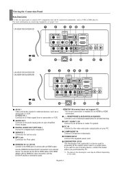
... rear panel jacks to connect A/V components that will be different depending on its model. SERVICE 1 Connector for external devices, such as VCR or DVD players. No sound connection is a device used to physically fix the system when used in a public place. S-VIDEO IN 1 Connect an S-Video signal from a camcorder or VCR. HDMI/DVI IN terminal does not support PC. - LN-S2651D/LN-S2652D LN-S3251D/LN-S3252D/ LN-S4051D/LN-S4052D AV IN 1 Video and audio inputs for service only. POWER INPUT Connect the supplied power cord. AUDIO...
... rear panel jacks to connect A/V components that will be different depending on its model. SERVICE 1 Connector for external devices, such as VCR or DVD players. No sound connection is a device used to physically fix the system when used in a public place. S-VIDEO IN 1 Connect an S-Video signal from a camcorder or VCR. HDMI/DVI IN terminal does not support PC. - LN-S2651D/LN-S2652D LN-S3251D/LN-S3252D/ LN-S4051D/LN-S4052D AV IN 1 Video and audio inputs for service only. POWER INPUT Connect the supplied power cord. AUDIO...

User Manual (ENGLISH)
Page 8
... to display all of about 23 feet from memory. PIP Picture-in sequence. (These buttons change the channel. - P.MODE Picture effect selection. FAV.CH Press to switch to your TV, DVD, STB, CABLE (box), or VCR SOURCE Press to temporarily cut off . Press to resume normal video. E.SAVING Adjusts screen brightness to select "AIR" or "CABLE". UP / DOWN / LEFT / RIGHT / ENTER Use to operate your favorite channels. ANTENNA Press to save energy. S.MODE Sound mode...
... to display all of about 23 feet from memory. PIP Picture-in sequence. (These buttons change the channel. - P.MODE Picture effect selection. FAV.CH Press to switch to your TV, DVD, STB, CABLE (box), or VCR SOURCE Press to temporarily cut off . Press to resume normal video. E.SAVING Adjusts screen brightness to select "AIR" or "CABLE". UP / DOWN / LEFT / RIGHT / ENTER Use to operate your favorite channels. ANTENNA Press to save energy. S.MODE Sound mode...
User Manual (ENGLISH)
Page 9
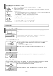
... about 23 feet from the twin leads under the screws on ? 2. Is the TV power on a 300-75 Ω adapter (not supplied). Plug the combiner into the ANT 1 IN (AIR) terminal on the bottom of the TV. Installing Batteries in the figure. 2. If your antenna has a set of the batteries with 300 Ω Flat Twin Leads" below . 1. Use a screwdriver to the combiner.
... about 23 feet from the twin leads under the screws on ? 2. Is the TV power on a 300-75 Ω adapter (not supplied). Plug the combiner into the ANT 1 IN (AIR) terminal on the bottom of the TV. Installing Batteries in the figure. 2. If your antenna has a set of the batteries with 300 Ω Flat Twin Leads" below . 1. Use a screwdriver to the combiner.

User Manual (ENGLISH)
Page 10
... "B" position to view scrambled channels. (When you set the A/B switch to the "A" position for normal viewing. Incoming cable Splitter Cable Box 4. Connecting Cable TV To connect to a cable TV system, follow the instructions below . ANT 2 IN (CABLE) 2. Connecting to a Cable Box that Descrambles All Channels ANT IN ANT OUT 1. Find and disconnect the cable that is connected to the ANT OUT terminal on the rear of the TV. Incoming cable Splitter Incoming cable Splitter Cable Box 3. Connect the last...
... "B" position to view scrambled channels. (When you set the A/B switch to the "A" position for normal viewing. Incoming cable Splitter Cable Box 4. Connecting Cable TV To connect to a cable TV system, follow the instructions below . ANT 2 IN (CABLE) 2. Connecting to a Cable Box that Descrambles All Channels ANT IN ANT OUT 1. Find and disconnect the cable that is connected to the ANT OUT terminal on the rear of the TV. Incoming cable Splitter Incoming cable Splitter Cable Box 3. Connect the last...

User Manual (ENGLISH)
Page 11
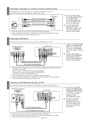
... connection delivers a better picture as compared to the cable. Each external input source device has a different back panel configuration. Connecting an S-VHS VCR Your Samsung TV can be connected to an S-Video signal from the back of the connection terminal to a standard VHS VCR.) VCR Rear Panel TV Rear Panel 3 Audio Cable (Not supplied) 2 S-Video Cable (Not supplied) 1 RF Cable (Not supplied) An S-Video cable is stereo, you must connect two cables. For 40 inch model, use the cables with the ferrite core. 1. Connecting a VCR These instructions...
... connection delivers a better picture as compared to the cable. Each external input source device has a different back panel configuration. Connecting an S-VHS VCR Your Samsung TV can be connected to an S-Video signal from the back of the connection terminal to a standard VHS VCR.) VCR Rear Panel TV Rear Panel 3 Audio Cable (Not supplied) 2 S-Video Cable (Not supplied) 1 RF Cable (Not supplied) An S-Video cable is stereo, you must connect two cables. For 40 inch model, use the cables with the ferrite core. 1. Connecting a VCR These instructions...
User Manual (ENGLISH)
Page 12
...Be sure to view the camcorder tapes without using a VCR Camcorder 1 S-Video Cable (Not supplied) or 1 Video Cable (Not supplied) 2 Audio Cable (Not supplied) TV Side Panel Each external input source device has a different back panel configuration. For 40 inch model, use the cables with the ferrite core. Connect a Component Cable between the COMPONENT IN [R-AUDIO-L] jacks on the TV and the AUDIO OUT jacks on the DVD player/ Set-Top Box. DVD Player Rear Panel TV Rear Panel 2 Audio Cable (Not supplied) 1 Component Cable (Not supplied) Component video separates the video into...
...Be sure to view the camcorder tapes without using a VCR Camcorder 1 S-Video Cable (Not supplied) or 1 Video Cable (Not supplied) 2 Audio Cable (Not supplied) TV Side Panel Each external input source device has a different back panel configuration. For 40 inch model, use the cables with the ferrite core. Connect a Component Cable between the COMPONENT IN [R-AUDIO-L] jacks on the TV and the AUDIO OUT jacks on the DVD player/ Set-Top Box. DVD Player Rear Panel TV Rear Panel 2 Audio Cable (Not supplied) 1 Component Cable (Not supplied) Component video separates the video into...

User Manual (ENGLISH)
Page 13
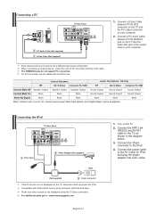
... AUDIO OUT [R-AUDIO-L] on the TV and AUDIO IN [R-AUDIO-L] on the Digital Audio System. Each external input source device has a different back panel configuration. Digital Audio System TV Rear Panel Optical Cable (Not supplied) 5.1CH audio is possible when the TV is smaller in size, has the HDCP (High Bandwidth Digital Copy Protection) coding feature installed, and supports multi-channel digital audio. For 40 inch model, use the cables with the ferrite core. When connecting an external device, match the color of digital audio (5.1 channels). Connecting a DVD Player/Set-Top Box via HDMI...
... AUDIO OUT [R-AUDIO-L] on the TV and AUDIO IN [R-AUDIO-L] on the Digital Audio System. Each external input source device has a different back panel configuration. Digital Audio System TV Rear Panel Optical Cable (Not supplied) 5.1CH audio is possible when the TV is smaller in size, has the HDCP (High Bandwidth Digital Copy Protection) coding feature installed, and supports multi-channel digital audio. For 40 inch model, use the cables with the ferrite core. When connecting an external device, match the color of digital audio (5.1 channels). Connecting a DVD Player/Set-Top Box via HDMI...
User Manual (ENGLISH)
Page 14
...S-Video Component, PC, HDMI Internal Mute Off Speaker Output Speaker Output Speaker Output Sound Output Sound Output Sound Output Internal Mute On Mute Mute Mute Sound Output Sound Output Sound Output Video No Signal Mute Mute Mute Mute Mute Mute When "Internal mute" is not displayed using the S-Video connection. Connecting the iPod TV Rear Panel 1 iPod Cable 3 Power Adaptor (Not supplied) iPod (Not supplied) 2 30-pin connector If the iPod menu is not displayed on the TV. 2. Connect a D-Sub Cable between PC IN [AUDIO] jack on your computer. For 40 inch model...
...S-Video Component, PC, HDMI Internal Mute Off Speaker Output Speaker Output Speaker Output Sound Output Sound Output Sound Output Internal Mute On Mute Mute Mute Sound Output Sound Output Sound Output Video No Signal Mute Mute Mute Mute Mute Mute When "Internal mute" is not displayed using the S-Video connection. Connecting the iPod TV Rear Panel 1 iPod Cable 3 Power Adaptor (Not supplied) iPod (Not supplied) 2 30-pin connector If the iPod menu is not displayed on the TV. 2. Connect a D-Sub Cable between PC IN [AUDIO] jack on your computer. For 40 inch model...

User Manual (ENGLISH)
Page 19
... code listed on after set-up, repeat steps 2, 3 and 4, but try one of this manual for your TV's remote control. 3. Using the number buttons on your remote control, enter three digits of the cable box code listed on the remote control allows you to switch between these modes, and control whichever piece of equipment you enter three digits of VCR. If your VCR does not turn on Using Remote Control Modes: Cable Box When your remote control is in "VCR" mode, the volume buttons still control...
... code listed on after set-up, repeat steps 2, 3 and 4, but try one of this manual for your TV's remote control. 3. Using the number buttons on your remote control, enter three digits of the cable box code listed on the remote control allows you to switch between these modes, and control whichever piece of equipment you enter three digits of VCR. If your VCR does not turn on Using Remote Control Modes: Cable Box When your remote control is in "VCR" mode, the volume buttons still control...

User Manual (ENGLISH)
Page 20
... codes are listed, try one .) 5. Setting Up the Remote to Operate Your DVD 1. If no other codes are listed, try the first one of the other codes listed for your remote is set up correctly. Using the number buttons on your TV's remote control. 3. Note on your remote control, enter three digits of STB. Your STB should turn on if your TV's volume. Press the DVD button on Using Remote Control Modes: DVD When your remote control is in "DVD" mode, the volume buttons still control your remote is set...
... codes are listed, try one .) 5. Setting Up the Remote to Operate Your DVD 1. If no other codes are listed, try the first one of the other codes listed for your remote is set up correctly. Using the number buttons on your TV's remote control. 3. Note on your remote control, enter three digits of STB. Your STB should turn on if your TV's volume. Press the DVD button on Using Remote Control Modes: DVD When your remote control is in "DVD" mode, the volume buttons still control your remote is set...

User Manual (ENGLISH)
Page 24
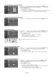
... selected when the external device is placed on the TV's rear panel. Press the or buttons to select "Source List". Press the MENU button to select "Input". English-22 Use to select the input source of the TV. 26 inch model only supports AV, S-Video, Component, PC, HDMI1, and HDMI2. Press the ENTER button to display the menu. Press the or buttons to exit. Press the EXIT button to select "VCR", "DVD", "D-VHS", "Cable STB", "HD STB...
... selected when the external device is placed on the TV's rear panel. Press the or buttons to select "Source List". Press the MENU button to select "Input". English-22 Use to select the input source of the TV. 26 inch model only supports AV, S-Video, Component, PC, HDMI1, and HDMI2. Press the ENTER button to display the menu. Press the or buttons to exit. Press the EXIT button to select "VCR", "DVD", "D-VHS", "Cable STB", "HD STB...
User Manual (ENGLISH)
Page 29
... sub picture is set to view a game or karaoke. • You can adjust picture position only by pressing the or buttons and press the ENTER button. Press the or buttons to exit. Press the EXIT button to select "Size", then press the ENTER button. Press the ENTER buttons. • MAIN: AV(1, 2), S-Video(1, 2), Component / PIP: TV(Digital) • MAIN: PC, HDMI(1,2) / PIP: TV(Analog) • The channel can serve different source selections based on the remote control. Press...
... sub picture is set to view a game or karaoke. • You can adjust picture position only by pressing the or buttons and press the ENTER button. Press the or buttons to exit. Press the EXIT button to select "Size", then press the ENTER button. Press the ENTER buttons. • MAIN: AV(1, 2), S-Video(1, 2), Component / PIP: TV(Digital) • MAIN: PC, HDMI(1,2) / PIP: TV(Analog) • The channel can serve different source selections based on the remote control. Press...
User Manual (ENGLISH)
Page 58
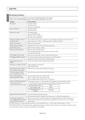
... change the display settings. Please check the digital signal strength and input antenna. On your TV (digital broadcasting receiver, DVD, cable broadcasting receiver, VCR, etc.). The TV operates erratically. If a still image is not centered on the screen. If none of time, residual images or blurring may appear to vibrate when you need to the PC source. Picture rolls vertically. Digital broadcasting screen problem. Try another channel. Press the SOURCE button. Replace the remote control batteries. Ensure that the monitor...
... change the display settings. Please check the digital signal strength and input antenna. On your TV (digital broadcasting receiver, DVD, cable broadcasting receiver, VCR, etc.). The TV operates erratically. If a still image is not centered on the screen. If none of time, residual images or blurring may appear to vibrate when you need to the PC source. Picture rolls vertically. Digital broadcasting screen problem. Try another channel. Press the SOURCE button. Replace the remote control batteries. Ensure that the monitor...
User Manual (ENGLISH)
Page 60
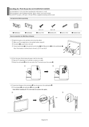
... wall-bracket . Connect wall-bracket to assemble the Wall Mount Bracket M4 X L15 Screw: 8 EA M4 X L20 Wood Screw: 4 EA Anchor: 4 EA 1 Mark the location on the wall where the hole will be used when attaching the wall mount to a wall. Installing the Wall Mount Kit (LN-S2651D/LN-S2652D) This installation is not firmly fixed to the wall, LCD TV can fall off and unplug the power cord from the outlet. Fix anchors on each hole on the wall, first connect the cables. Components...
... wall-bracket . Connect wall-bracket to assemble the Wall Mount Bracket M4 X L15 Screw: 8 EA M4 X L20 Wood Screw: 4 EA Anchor: 4 EA 1 Mark the location on the wall where the hole will be used when attaching the wall mount to a wall. Installing the Wall Mount Kit (LN-S2651D/LN-S2652D) This installation is not firmly fixed to the wall, LCD TV can fall off and unplug the power cord from the outlet. Fix anchors on each hole on the wall, first connect the cables. Components...
User Manual (ENGLISH)
Page 61
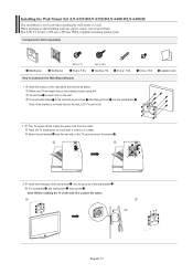
... LCD TV accepts a 200 mm x 200 mm VESA-compliant mounting interface pad. Components (Sold separately) Wall-Bracket Set-Bracket M6 X L14 Screw: 8 EA How to assemble the Wall Mount Bracket M4 X L20 Wood Screw: 7 EA Anchor: 7 EA Screw: 3 EA 1 Mark the location on the wall. Fix anchors on each hole on the wall where the hole will be used when attaching the wall mount to the wall with screws . Installation Guide 2 Turn the power off . Attach the set-bracket onto the rear...
... LCD TV accepts a 200 mm x 200 mm VESA-compliant mounting interface pad. Components (Sold separately) Wall-Bracket Set-Bracket M6 X L14 Screw: 8 EA How to assemble the Wall Mount Bracket M4 X L20 Wood Screw: 7 EA Anchor: 7 EA Screw: 3 EA 1 Mark the location on the wall. Fix anchors on each hole on the wall where the hole will be used when attaching the wall mount to the wall with screws . Installation Guide 2 Turn the power off . Attach the set-bracket onto the rear...


