
User Manual (ENGLISH)
Page 2
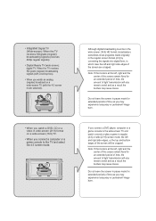
... digital form, in pause mode for extended periods of time as you may experience temporary or permanent image burn. • Digital Ready TV: When the TV receives HD-grade signals (and the set-top box output is 1080i). Although digital broadcasting must be able to watch the program but ... and as a result the borders may leave traces. Precautions When Displaying a Still Image A still image may cause permanent damage to the TV screen. • Digital Ready TV: When you select the regular screen (4:3) mode to watch an SD-grade digital broadcast (and the set-top box output is 480p). ...
... digital form, in pause mode for extended periods of time as you may experience temporary or permanent image burn. • Digital Ready TV: When the TV receives HD-grade signals (and the set-top box output is 1080i). Although digital broadcasting must be able to watch the program but ... and as a result the borders may leave traces. Precautions When Displaying a Still Image A still image may cause permanent damage to the TV screen. • Digital Ready TV: When you select the regular screen (4:3) mode to watch an SD-grade digital broadcast (and the set-top box output is 480p). ...
User Manual (ENGLISH)
Page 3
...remain varied and as a result the borders may leave traces. • Integrated Digital TV (Wide-screen): When the TV receives SD-grade (regular) broadcasting signals (receives 480p regular signals). • Digital Ready TV (wide-screen): digital TV: When the TV receives SD-grade (regular) broadcasting signals (with a set-top box). • ... case the left and right side edges of the screen are cropped. If you connect a DVD player, computer or a game console to the TV and select the 4:3 screen mode. Note: If the borders at the left , right and the center of the screen remain fixed for an ...
...remain varied and as a result the borders may leave traces. • Integrated Digital TV (Wide-screen): When the TV receives SD-grade (regular) broadcasting signals (receives 480p regular signals). • Digital Ready TV (wide-screen): digital TV: When the TV receives SD-grade (regular) broadcasting signals (with a set-top box). • ... case the left and right side edges of the screen are cropped. If you connect a DVD player, computer or a game console to the TV and select the 4:3 screen mode. Note: If the borders at the left , right and the center of the screen remain fixed for an ...

User Manual (ENGLISH)
Page 4
... Connecting VHF and UHF Antennas 7 Antennas with 300-ohm Flat Twin Leads 7 Antennas with 75-ohm Round Leads 8 Separate VHF and UHF Antennas 8 Connecting Cable TV 9 Cable without a Cable Box 9 Connecting to a Cable Box that Descrambles All Channels . . . . . 9 Connecting to a Cable Box that Descrambles Some Channels . ... 4: Picture Control Using Automatic Picture Settings 29 Customizing the Picture 30 Adjusting the Color Tone 31 Changing the Screen Size 32 Zoom 33 Freezing the Picture 34 Digital Noise Reduction 34 DNIe (Digital Natural Image engine 35 My Color Control 36 Easy...
... Connecting VHF and UHF Antennas 7 Antennas with 300-ohm Flat Twin Leads 7 Antennas with 75-ohm Round Leads 8 Separate VHF and UHF Antennas 8 Connecting Cable TV 9 Cable without a Cable Box 9 Connecting to a Cable Box that Descrambles All Channels . . . . . 9 Connecting to a Cable Box that Descrambles Some Channels . ... 4: Picture Control Using Automatic Picture Settings 29 Customizing the Picture 30 Adjusting the Color Tone 31 Changing the Screen Size 32 Zoom 33 Freezing the Picture 34 Digital Noise Reduction 34 DNIe (Digital Natural Image engine 35 My Color Control 36 Easy...
User Manual (ENGLISH)
Page 5
... Mute 48 Selecting the Main or Sub (PIP) Sound 49 Chapter 6: Channel Control Fine Tuning Channels 50 Chapter 7: PC Display Using Your TV as a Computer (PC) Display 51 Setting Up Your PC Software (Based on Windows XP 51 How to Auto Adjust 52 Adjusting the Screen... the stand 77 Disconnecting the stand 77 Installing the Wall Mount Kit (LN-R238W / LN-R237W / LN-R268W / LN-R2668W / LN-R267W) . . . 78 Installing the Wall Mount Kit (LN-R328W / LN-R3228W / LN-R327W 79 Using the Anti-Theft Kensington Lock 80 Using Your TV in Another Country 80 Specifications 81 Display Modes 83 Contents-2
... Mute 48 Selecting the Main or Sub (PIP) Sound 49 Chapter 6: Channel Control Fine Tuning Channels 50 Chapter 7: PC Display Using Your TV as a Computer (PC) Display 51 Setting Up Your PC Software (Based on Windows XP 51 How to Auto Adjust 52 Adjusting the Screen... the stand 77 Disconnecting the stand 77 Installing the Wall Mount Kit (LN-R238W / LN-R237W / LN-R268W / LN-R2668W / LN-R267W) . . . 78 Installing the Wall Mount Kit (LN-R328W / LN-R3228W / LN-R327W 79 Using the Anti-Theft Kensington Lock 80 Using Your TV in Another Country 80 Specifications 81 Display Modes 83 Contents-2
User Manual (ENGLISH)
Page 6
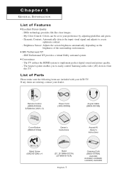
... My Color Control: Colors can be set to easily control Samsung audio-video (AV) devices from this TV. SRS TruSurround XT - SRS TruSurround XT provides a virtual Dolby...visual signal and adjusts to implement perfect digital sound and picture quality. - The TV utilizes the HDMI system to create optimum contrast. - If any items are included... Owner's Instructions M4 X L16 Stand Screw (6002-001294) x 4 Stand (23", 26" BN96-01727A) (32" BN96-01733A) English-1 Cleaning Cloth (BN63-01798A) LN-R238W, LN-R268W, LN-R2668W, LN-R328W, LN-R3228W Chapter 1 G E N E R A L I N F O R M AT I O N...
... My Color Control: Colors can be set to easily control Samsung audio-video (AV) devices from this TV. SRS TruSurround XT - SRS TruSurround XT provides a virtual Dolby...visual signal and adjusts to implement perfect digital sound and picture quality. - The TV utilizes the HDMI system to create optimum contrast. - If any items are included... Owner's Instructions M4 X L16 Stand Screw (6002-001294) x 4 Stand (23", 26" BN96-01727A) (32" BN96-01733A) English-1 Cleaning Cloth (BN63-01798A) LN-R238W, LN-R268W, LN-R2668W, LN-R328W, LN-R3228W Chapter 1 G E N E R A L I N F O R M AT I O N...
User Manual (ENGLISH)
Page 7
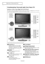
... R M AT I O N Familiarizing Yourself with Your New TV Buttons on the Lower-Right Part of the Panel The buttons on the lower-right panel control your choice on the on-screen menu. LN-R328W - LN-R267W - CH Press to decrease or increase the volume. LN-R3228W - REMOTE CONTROL SENSOR Aim the remote control towards... this spot on -screen menu of your TV's features. - SPEAKERS English-2 LN-R237W - POWER INDICATOR Blinks and...
... R M AT I O N Familiarizing Yourself with Your New TV Buttons on the Lower-Right Part of the Panel The buttons on the lower-right panel control your choice on the on-screen menu. LN-R328W - LN-R267W - CH Press to decrease or increase the volume. LN-R3228W - REMOTE CONTROL SENSOR Aim the remote control towards... this spot on -screen menu of your TV's features. - SPEAKERS English-2 LN-R237W - POWER INDICATOR Blinks and...
User Manual (ENGLISH)
Page 8
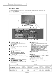
... supplied power cord. For more information on your amplifier. KENSINGTON LOCK Refer to the audio input jack on page 80. PC IN Connect to a cable TV system. HEADPHONE JACK Connect a set of a device with an S-Video output, such as a camcorder or VCR. ANT IN Connect to an antenna or to the...
... supplied power cord. For more information on your amplifier. KENSINGTON LOCK Refer to the audio input jack on page 80. PC IN Connect to a cable TV system. HEADPHONE JACK Connect a set of a device with an S-Video output, such as a camcorder or VCR. ANT IN Connect to an antenna or to the...

User Manual (ENGLISH)
Page 9
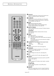
... select on the current broadcast. (See page 21) EXIT Press to exit the menu. English-4 When using the remote, always point it directly at the TV. For example, to select channel 121, press "+100", then press "2" and "1". (See page 19) MUTE Press to temporarily cut off the sound. (See ... 21) CAPTION Controls the caption decoder. (See page 71) PIP Picture-in-Picture ON/OFF. (See page 40) SLEEP Press to select a time for the TV to turn off . (See page 19) STILL Press to stop the action during a particular scene. G E N E R A L I N F O R M AT I O N Remote Control You can use the remote ...
... select on the current broadcast. (See page 21) EXIT Press to exit the menu. English-4 When using the remote, always point it directly at the TV. For example, to select channel 121, press "+100", then press "2" and "1". (See page 19) MUTE Press to temporarily cut off the sound. (See ... 21) CAPTION Controls the caption decoder. (See page 71) PIP Picture-in-Picture ON/OFF. (See page 40) SLEEP Press to select a time for the TV to turn off . (See page 19) STILL Press to stop the action during a particular scene. G E N E R A L I N F O R M AT I O N Remote Control You can use the remote ...
User Manual (ENGLISH)
Page 10
...) - G E N E R A L I N F O R M AT I O N Anynet Press the Anynet button to bring up the Anynet menu. (Refer to "Anynet AV Owner's Instructions".) S.MODE Adjusts the TV sound by selecting one of the preset factory settings (or selects your remote does not work, change the screen size. (See page 33) PC Press...Television Stereo) Press to choose stereo, mono or Separate Audio Program (SAP broadcast). (See page 46) AUTO PROG. Press to automatically store selected TV/Cable channels. (See page 25) ADD/DEL Use to store and delete channels to/from memory. (See page 26) DNIe DNIe Demo On/...
...) - G E N E R A L I N F O R M AT I O N Anynet Press the Anynet button to bring up the Anynet menu. (Refer to "Anynet AV Owner's Instructions".) S.MODE Adjusts the TV sound by selecting one of the preset factory settings (or selects your remote does not work, change the screen size. (See page 33) PC Press...Television Stereo) Press to choose stereo, mono or Separate Audio Program (SAP broadcast). (See page 46) AUTO PROG. Press to automatically store selected TV/Cable channels. (See page 25) ADD/DEL Use to store and delete channels to/from memory. (See page 26) DNIe DNIe Demo On/...

User Manual (ENGLISH)
Page 11
... F O R M AT I O N Installing Batteries in a cool, dry place if you won't be used up to match the "+" and "-" ends of the batteries reversed? 3. Is the TV power on? 2. Is there a special fluorescent light or a neon sign nearby? The remote control can be using the remote control for about one year.) If ...Check the following: 1. Is there a power outage, or is the power cord unplugged? 5. Make sure to about 23 feet from the TV. (Assuming typical TV usage, the batteries last for a long time. English-6 Remove the batteries and store them in the Remote Control 1 Slide the cover ...
... F O R M AT I O N Installing Batteries in a cool, dry place if you won't be used up to match the "+" and "-" ends of the batteries reversed? 3. Is the TV power on? 2. Is there a special fluorescent light or a neon sign nearby? The remote control can be using the remote control for about one year.) If ...Check the following: 1. Is there a power outage, or is the power cord unplugged? 5. Make sure to about 23 feet from the TV. (Assuming typical TV usage, the batteries last for a long time. English-6 Remove the batteries and store them in the Remote Control 1 Slide the cover ...
User Manual (ENGLISH)
Page 12
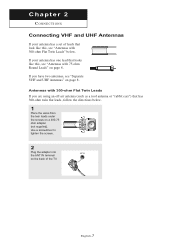
If your antenna has a set of the TV. If you are using an off-air antenna (such as a roof antenna or "rabbit ears") that look like this, see "Separate VHF and UHF Antennas" ...
If your antenna has a set of the TV. If you are using an off-air antenna (such as a roof antenna or "rabbit ears") that look like this, see "Separate VHF and UHF Antennas" ...

User Manual (ENGLISH)
Page 13
UHF VHF ANT IN English-8 Separate VHF and UHF Antennas If you have two separate antennas for your TV (one VHF and one UHF), you must combine the two antenna signals before connecting the antennas to the combiner. CONNECTIONS Antennas with 75-ohm Round Leads 1 Plug the antenna lead into the ANT IN terminal on the back of the TV. This procedure requires an optional combiner-adapter (available at most electronics shops). 1 Connect both antenna leads to the TV. UHF VHF 2 Plug the combiner into the ANT IN terminal on the back of the TV.
UHF VHF ANT IN English-8 Separate VHF and UHF Antennas If you have two separate antennas for your TV (one VHF and one UHF), you must combine the two antenna signals before connecting the antennas to the combiner. CONNECTIONS Antennas with 75-ohm Round Leads 1 Plug the antenna lead into the ANT IN terminal on the back of the TV. This procedure requires an optional combiner-adapter (available at most electronics shops). 1 Connect both antenna leads to the TV. UHF VHF 2 Plug the combiner into the ANT IN terminal on the back of the TV.
User Manual (ENGLISH)
Page 14
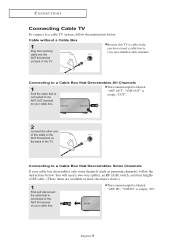
...a Cable Box that Descrambles All Channels 1 Find the cable that is connected to the ANT IN terminal on the back of the TV. CONNECTIONS Connecting Cable TV To connect to a cable TV system, follow the instructions below . ANT IN ANT OUT This terminal might be labeled "ANT OUT", "VHF OUT" or simply,... "OUT". 2 Connect the other end of this TV is connected to view unscrambled cable channels. You will need a two-way splitter, an RF (A/B) switch, and four lengths of RF cable. (These items ...
...a Cable Box that Descrambles All Channels 1 Find the cable that is connected to the ANT IN terminal on the back of the TV. CONNECTIONS Connecting Cable TV To connect to a cable TV system, follow the instructions below . ANT IN ANT OUT This terminal might be labeled "ANT OUT", "VHF OUT" or simply,... "OUT". 2 Connect the other end of this TV is connected to view unscrambled cable channels. You will need a two-way splitter, an RF (A/B) switch, and four lengths of RF cable. (These items ...
User Manual (ENGLISH)
Page 15
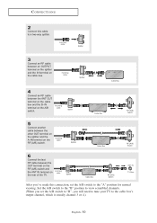
...Box RF (A/B) Switch 6 Connect the last RF cable between the other OUT terminal on the splitter and the A-IN terminal on the rear of the TV. Incoming cable Splitter 3 Connect an RF cable between the ANT OUT terminal on the cable box and the B-IN terminal on the cable box. ... terminal on the splitter and the IN terminal on the A/B switch. CONNECTIONS 2 Connect this connection, set the A/B switch to "B", you will need to tune your TV to the cable box's output channel, which is usually channel 3 or 4.) English-10 Set the A/B switch to the "B" position to view scrambled channels. (When...
...Box RF (A/B) Switch 6 Connect the last RF cable between the other OUT terminal on the splitter and the A-IN terminal on the rear of the TV. Incoming cable Splitter 3 Connect an RF cable between the ANT OUT terminal on the cable box and the B-IN terminal on the cable box. ... terminal on the splitter and the IN terminal on the A/B switch. CONNECTIONS 2 Connect this connection, set the A/B switch to "B", you will need to tune your TV to the cable box's output channel, which is usually channel 3 or 4.) English-10 Set the A/B switch to the "B" position to view scrambled channels. (When...

User Manual (ENGLISH)
Page 16
... Cable or Antenna VCR Rear Panel 3 Connect an RF cable between the ANT OUT terminal on the VCR and the ANT IN terminal on the TV. VCR Rear Panel TV Rear Panel RF Cable (Option) English-11 CONNECTIONS Connecting a VCR These instructions assume that you have already connected your...
... Cable or Antenna VCR Rear Panel 3 Connect an RF cable between the ANT OUT terminal on the VCR and the ANT IN terminal on the TV. VCR Rear Panel TV Rear Panel RF Cable (Option) English-11 CONNECTIONS Connecting a VCR These instructions assume that you have already connected your...

User Manual (ENGLISH)
Page 17
CONNECTIONS 4 Connect an audio cable between the VIDEO OUT jack on the VCR and the AV IN [VIDEO] jack on the TV. English-12 VCR Rear Panel TV Rear Panel Audio Cable (Option) Video Cable (Option) RF Cable (Option) Follow the instructions in "Viewing a VCR or Camcorder Tape" to the left and right... a video cable between the AUDIO OUT jacks on the VCR and the AV IN [R-AUDIO-L] jacks on the TV. VCR Rear Panel TV Rear Panel Audio Cable (Option) RF Cable (Option) If you have a "mono" (non-stereo) VCR, use the Y-connector (not supplied) to hook up to view ...
CONNECTIONS 4 Connect an audio cable between the VIDEO OUT jack on the VCR and the AV IN [VIDEO] jack on the TV. English-12 VCR Rear Panel TV Rear Panel Audio Cable (Option) Video Cable (Option) RF Cable (Option) Follow the instructions in "Viewing a VCR or Camcorder Tape" to the left and right... a video cable between the AUDIO OUT jacks on the VCR and the AV IN [R-AUDIO-L] jacks on the TV. VCR Rear Panel TV Rear Panel Audio Cable (Option) RF Cable (Option) If you have a "mono" (non-stereo) VCR, use the Y-connector (not supplied) to hook up to view ...

User Manual (ENGLISH)
Page 18
English-13 CONNECTIONS Connecting an S-VHS VCR Your Samsung TV can be connected to an S-Video signal from an S-VHS VCR. (This connection ... Connect an audio cable between the S-VIDEO OUT jack on the VCR and the S-VIDEO IN jack on the TV. VCR Rear Panel TV Rear Panel Audio Cable (Option) S-Video Cable (Option) RF Cable (Option) An S-Video cable is usually... included with an S-VHS VCR. (If not, check your TV. VCR Rear Panel TV Rear Panel Audio Cable (Option) RF Cable (Option) 3 Connect an S-Video cable between the AUDIO OUT jacks...
English-13 CONNECTIONS Connecting an S-VHS VCR Your Samsung TV can be connected to an S-Video signal from an S-VHS VCR. (This connection ... Connect an audio cable between the S-VIDEO OUT jack on the VCR and the S-VIDEO IN jack on the TV. VCR Rear Panel TV Rear Panel Audio Cable (Option) S-Video Cable (Option) RF Cable (Option) An S-Video cable is usually... included with an S-VHS VCR. (If not, check your TV. VCR Rear Panel TV Rear Panel Audio Cable (Option) RF Cable (Option) 3 Connect an S-Video cable between the AUDIO OUT jacks...

User Manual (ENGLISH)
Page 19
... source device has a different back panel configuration. CONNECTIONS Connecting a DVD Player The rear panel jacks on your TV make it easy to connect a DVD player to your DVD player owner's manual. DVD Player Rear Panel TV Rear Panel Audio Cable (Option) 2 Connect a component cable between the COMPONENT IN 1 or COMPONENT IN ...2 [R-AUDIO-L] jacks on the TV and the AUDIO OUT jacks on the DVD player. For example, if connecting the video cable to Component In 1, connect the audio cable ...
... source device has a different back panel configuration. CONNECTIONS Connecting a DVD Player The rear panel jacks on your TV make it easy to connect a DVD player to your DVD player owner's manual. DVD Player Rear Panel TV Rear Panel Audio Cable (Option) 2 Connect a component cable between the COMPONENT IN 1 or COMPONENT IN ...2 [R-AUDIO-L] jacks on the TV and the AUDIO OUT jacks on the DVD player. For example, if connecting the video cable to Component In 1, connect the audio cable ...

User Manual (ENGLISH)
Page 20
Connecting an Amplifier/DVD Home Theater 1 Connect an audio cable between the AUDIO OUT [R-AUDIO-L] jacks on the TV and the AUDIO IN jacks on the Set-top box. Set-Top Box Rear Panel TV Rear Panel Audio Cable (Option) 2 Connect a component cable between the COMPONENT IN 1 or COMPONENT IN 2 [R-AUDIO-L] ... for a typical Set-top box are shown below. 1 Connect an audio cable between the COMPONENT IN 1 or COMPONENT IN 2 [PR, PB, Y] jacks on the TV and the COMPONENT [Y, PB, PR] jacks on the Amplifier/ DVD Home Theater. Set-Top Box Rear Panel Audio Cable (Option) Component Cable (Option...
Connecting an Amplifier/DVD Home Theater 1 Connect an audio cable between the AUDIO OUT [R-AUDIO-L] jacks on the TV and the AUDIO IN jacks on the Set-top box. Set-Top Box Rear Panel TV Rear Panel Audio Cable (Option) 2 Connect a component cable between the COMPONENT IN 1 or COMPONENT IN 2 [R-AUDIO-L] ... for a typical Set-top box are shown below. 1 Connect an audio cable between the COMPONENT IN 1 or COMPONENT IN 2 [PR, PB, Y] jacks on the TV and the COMPONENT [Y, PB, PR] jacks on the Amplifier/ DVD Home Theater. Set-Top Box Rear Panel Audio Cable (Option) Component Cable (Option...

User Manual (ENGLISH)
Page 21
CONNECTIONS Connecting a DVD/Set-top box via DVI This can be applied only if there is the DVI Output connector on the external device. 1 Connect a DVI-to -HDMI Cable (Option) English-16 DVD Player Rear Panel TV Rear Panel Audio Cable (Option) DVI-to -HDMI cable or DVI-HDMI adapter between the DVI IN [R-AUDIO-L] jack on the TV and the AUDIO OUT jacks on the DVD player/Set-top box. DVD Player Rear Panel TV Rear Panel DVI-to-HDMI Cable (Option) 2 Connect an audio cable between the HDMI/DVI connector on the TV and the DVI connector on the DVD player/Set-top box.
CONNECTIONS Connecting a DVD/Set-top box via DVI This can be applied only if there is the DVI Output connector on the external device. 1 Connect a DVI-to -HDMI Cable (Option) English-16 DVD Player Rear Panel TV Rear Panel Audio Cable (Option) DVI-to -HDMI cable or DVI-HDMI adapter between the DVI IN [R-AUDIO-L] jack on the TV and the AUDIO OUT jacks on the DVD player/Set-top box. DVD Player Rear Panel TV Rear Panel DVI-to-HDMI Cable (Option) 2 Connect an audio cable between the HDMI/DVI connector on the TV and the DVI connector on the DVD player/Set-top box.


