Service Manual
Page 4
... ...14-5 14-5 Preset Timing Modes ...14-6 14-6 Panel Description ...14-7 Operating Instructions and Installation ...10-1 10-1 Front ...10-1 10-2 Rear ...10-2 10-3 Monitor Assembly ...10-3 10-4 Attaching a Base ...10-4 11. Schematic Diagrams ...9-1 9-1 INPUT ...9-1 9-2 DCINPUT ...9-2 9-3 SCALER ...9-3 9-4 POWER ...9-4 9-5 POWER ...9-5 9-6 KEYPAD ...9-6 10. Disassembly and Reassembly ...11-1 11-1 Disassembly Block ...11-1 11-2 Reassembly ...11-4 12. Circuit...
... ...14-5 14-5 Preset Timing Modes ...14-6 14-6 Panel Description ...14-7 Operating Instructions and Installation ...10-1 10-1 Front ...10-1 10-2 Rear ...10-2 10-3 Monitor Assembly ...10-3 10-4 Attaching a Base ...10-4 11. Schematic Diagrams ...9-1 9-1 INPUT ...9-1 9-2 DCINPUT ...9-2 9-3 SCALER ...9-3 9-4 POWER ...9-4 9-5 POWER ...9-5 9-6 KEYPAD ...9-6 10. Disassembly and Reassembly ...11-1 11-1 Disassembly Block ...11-1 11-2 Reassembly ...11-4 12. Circuit...
Service Manual
Page 6
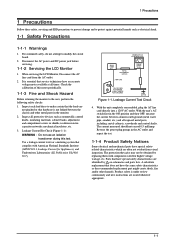
Disconnect the AC power and DC power jack before servicing. 1-1-2 Servicing the LCD Monitor 1. Inspect each lead dress to the user, perform the following safety checks: 1. Use a leakage current tester or a metering system that complies with components rated ...might create shock, fire and/or other metal parts in the monitor. 2. When servicing the LCD Monitor, Disconnect the AC line cord from visual inspection. The current measured should not exceed 0.5 milliamp. The protection they give may not be obtained by on schematics and parts lists. Reverse the power-plug prongs in the ON...
Disconnect the AC power and DC power jack before servicing. 1-1-2 Servicing the LCD Monitor 1. Inspect each lead dress to the user, perform the following safety checks: 1. Use a leakage current tester or a metering system that complies with components rated ...might create shock, fire and/or other metal parts in the monitor. 2. When servicing the LCD Monitor, Disconnect the AC line cord from visual inspection. The current measured should not exceed 0.5 milliamp. The protection they give may not be obtained by on schematics and parts lists. Reverse the power-plug prongs in the ON...

Service Manual
Page 36
This Document can not be used without Samsung s authorization. 9-1 INPUT 9 Schematic Diagrams 9-1 9 Schematic Diagrams -
This Document can not be used without Samsung s authorization. 9-1 INPUT 9 Schematic Diagrams 9-1 9 Schematic Diagrams -


