Service Manual
Page 4
Contents 9. Reference Infomation ...14-1 14-1 Technical Terms ...14-1 14-2 Connecting the monitor ...14-3 14-3 Pin Assignments ...14-4 14-4 Timing Chart ...14-5 14-5 Preset Timing Modes ...14-6 14-6 Panel Description ...14-7 Disassembly and Reassembly ...11-1 11-1 Disassembly Block ...11-1 11-2 Reassembly ...11-4 12. Schematic Diagrams ...9-1 9-1 INPUT ...9-1 9-2 DCINPUT ...9-2 9-3 SCALER ...9-3 9-4 POWER ...9-4 9-5 POWER ...9-5 9-6 KEYPAD ...9-6 10. Circuit Descriptions...
Contents 9. Reference Infomation ...14-1 14-1 Technical Terms ...14-1 14-2 Connecting the monitor ...14-3 14-3 Pin Assignments ...14-4 14-4 Timing Chart ...14-5 14-5 Preset Timing Modes ...14-6 14-6 Panel Description ...14-7 Disassembly and Reassembly ...11-1 11-1 Disassembly Block ...11-1 11-2 Reassembly ...11-4 12. Schematic Diagrams ...9-1 9-1 INPUT ...9-1 9-2 DCINPUT ...9-2 9-3 SCALER ...9-3 9-4 POWER ...9-4 9-5 POWER ...9-5 9-6 KEYPAD ...9-6 10. Circuit Descriptions...
Service Manual
Page 6
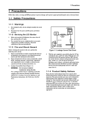
... (ANSI C101.1, Leakage Current for higher voltage, wattage, etc. Disconnect the AC power and DC power jack before servicing. 1-1-2 Servicing the LCD Monitor 1. Parts that hardware is not lodged between a known earth ground (metal water pipe, conduit, etc.) and all exposed metal parts, including... 0.5 milliamp. Leakage Current Test Circuit 4. The protection they give may not be obtained by on schematics and parts lists. With the unit's AC switch first in the monitor. 2. Reverse the power-plug prongs in the AC outlet and repeat the test. 1-1-4 Product Safety...
... (ANSI C101.1, Leakage Current for higher voltage, wattage, etc. Disconnect the AC power and DC power jack before servicing. 1-1-2 Servicing the LCD Monitor 1. Parts that hardware is not lodged between a known earth ground (metal water pipe, conduit, etc.) and all exposed metal parts, including... 0.5 milliamp. Leakage Current Test Circuit 4. The protection they give may not be obtained by on schematics and parts lists. With the unit's AC switch first in the monitor. 2. Reverse the power-plug prongs in the AC outlet and repeat the test. 1-1-4 Product Safety...

Service Manual
Page 36
This Document can not be used without Samsung s authorization. 9-1 INPUT 9 Schematic Diagrams 9-1 9 Schematic Diagrams -
This Document can not be used without Samsung s authorization. 9-1 INPUT 9 Schematic Diagrams 9-1 9 Schematic Diagrams -


