
User Manual
Page 4
...product in serious harm (suffocation) if children play with a slightly moistened, soft cloth. Ensure that the packaging vinyl is a clearance of the TFT-LCD screen, wipe with it may result in fire. 3 When putting the product down softly. • Otherwise, this may result in damage to the ...case or the surface of more than 4 inches (10 cm) from children. • Otherwise, it may result in fire due to the screen display. Install your body on the floor. • Otherwise, this may result in damage to an increase in the discoloration and distortion of the structure and...
...product in serious harm (suffocation) if children play with a slightly moistened, soft cloth. Ensure that the packaging vinyl is a clearance of the TFT-LCD screen, wipe with it may result in fire. 3 When putting the product down softly. • Otherwise, this may result in damage to the ...case or the surface of more than 4 inches (10 cm) from children. • Otherwise, it may result in fire due to the screen display. Install your body on the floor. • Otherwise, this may result in damage to an increase in the discoloration and distortion of the structure and...

User Manual
Page 10
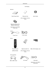
... package box by Check the contents of the package box. Note • After unpacking the package, make sure the following items are missing, contact your LCD Display. Introduction Package Contents Note Please make sure to check the contents of the package. • Make sure to buy optional items. Checking the Contents of...
... package box by Check the contents of the package box. Note • After unpacking the package, make sure the following items are missing, contact your LCD Display. Introduction Package Contents Note Please make sure to check the contents of the package. • Make sure to buy optional items. Checking the Contents of...
User Manual
Page 11
Manuals Introduction LCD Display Quick Setup Guide Warranty Card (Not available in all locations) User's Guide MagicInfo Software CD, MagicInfo Manual CD (Applicable to the DXN-2 model only) Cables Power Cord Others D-Sub Cable Remote Control (BP59-00138A) Sold separately Batteries (AAA X 2) BNC to RCA Adaptor Jack (Not available in all locations) BNC to BNC Cable DVI Cable 10 LAN Cable (Applicable to the DXN-2 model only)
Manuals Introduction LCD Display Quick Setup Guide Warranty Card (Not available in all locations) User's Guide MagicInfo Software CD, MagicInfo Manual CD (Applicable to the DXN-2 model only) Cables Power Cord Others D-Sub Cable Remote Control (BP59-00138A) Sold separately Batteries (AAA X 2) BNC to RCA Adaptor Jack (Not available in all locations) BNC to BNC Cable DVI Cable 10 LAN Cable (Applicable to the DXN-2 model only)

User Manual
Page 12
... buttons Moves from the menu. Also use to exit the OSD menu or return to the previous menu. Sold separately Introduction Wall Mount KIT Your LCD Display Front RGB to BNC Cable MENU button [MENU] Opens the on the screen, press the button to adjust volume.
... buttons Moves from the menu. Also use to exit the OSD menu or return to the previous menu. Sold separately Introduction Wall Mount KIT Your LCD Display Front RGB to BNC Cable MENU button [MENU] Opens the on the screen, press the button to adjust volume.

User Manual
Page 13
... the PIP button to Connecting Cables under Setup. Remote Control Sensor Aim the remote control towards this button for turning the LCD Display on the models equipped with an auto brightness sensor. Brightness Sensor (Optional) Automatically detects the surrounding brightness it is activated ...only on and off. The LCD Display 's configuration at the back may vary slightly depending on the LCD Display. More than one PIP cannot overlap on screen as BNC and the component use the same terminal...
... the PIP button to Connecting Cables under Setup. Remote Control Sensor Aim the remote control towards this button for turning the LCD Display on the models equipped with an auto brightness sensor. Brightness Sensor (Optional) Automatically detects the surrounding brightness it is activated ...only on and off. The LCD Display 's configuration at the back may vary slightly depending on the LCD Display. More than one PIP cannot overlap on screen as BNC and the component use the same terminal...

User Manual
Page 14
... (Digital PC) DVI/RGB AUDIO IN (PC/DVI Audio Connection Terminal (Input)) AV/COMPONENT AUDIO IN [R - L] Connect the port of the LCD Display. RS232C OUT/IN (RS232C Serial PORT) MDC(Multiple Display Control) Program Port RGB IN (PC Connection Terminal (Input)) • Use a D-Sub Cable (15 pin D-Sub) - L ] port of the DVD, VCR...
... (Digital PC) DVI/RGB AUDIO IN (PC/DVI Audio Connection Terminal (Input)) AV/COMPONENT AUDIO IN [R - L] Connect the port of the LCD Display. RS232C OUT/IN (RS232C Serial PORT) MDC(Multiple Display Control) Program Port RGB IN (PC Connection Terminal (Input)) • Use a D-Sub Cable (15 pin D-Sub) - L ] port of the DVD, VCR...

User Manual
Page 15
...HD or 10 HD monitors can be connected (May differ depending on the product). Up to HDMI cable 1.0 can be supported. The number of LCD Displays that can be connected (May not be connected to the loopout depends on the cables, signal source, etc. AUDIO OUT Headphone/External speaker output terminal... at the back of your digital output device using a HDMI cable. With cables or signal source where there is no degradation, up to 10 LCD Displays can be supported depending on the connected cable). AV IN [VIDEO] Connect the [ VIDEO ] terminal of your monitor to the video output terminal...
...HD or 10 HD monitors can be connected (May differ depending on the product). Up to HDMI cable 1.0 can be supported. The number of LCD Displays that can be connected (May not be connected to the loopout depends on the cables, signal source, etc. AUDIO OUT Headphone/External speaker output terminal... at the back of your digital output device using a HDMI cable. With cables or signal source where there is no degradation, up to 10 LCD Displays can be supported depending on the connected cable). AV IN [VIDEO] Connect the [ VIDEO ] terminal of your monitor to the video output terminal...

User Manual
Page 16
...] --> Blue port input - Introduction - Remote Control Note The performance of the remote control may be affected by a TV or other electronic device operating near the LCD Display , causing a malfunction due to the DXN-2 model only. Note See Connecting Cables for the input ports below . • [R/Y] --> Green port input • [G/PB] --> Blue port...
...] --> Blue port input - Introduction - Remote Control Note The performance of the remote control may be affected by a TV or other electronic device operating near the LCD Display , causing a malfunction due to the DXN-2 model only. Note See Connecting Cables for the input ports below . • [R/Y] --> Green port input • [G/PB] --> Blue port...

User Manual
Page 17
... input signal SOURCE. POWER 2. OFF 3. This function does not work for this LCD Display. D.MENU 8. Press to select Digital channels. Adjusts the audio volume. Number Buttons 4. DEL ton / GUIDE but- 5. + VOL 6. DTV menu display - SOURCE 7. Changing the SOURCE is used functions. 16 TOOLS Turns the product On.... Turns the product Off. Press the button to the LCD Display at the time. Introduction POWER OFF Number Buttons DEL + VOL - / GUIDE button SOURCE D.MENU TOOLS Up-Down Left-Right ...
... input signal SOURCE. POWER 2. OFF 3. This function does not work for this LCD Display. D.MENU 8. Press to select Digital channels. Adjusts the audio volume. Number Buttons 4. DEL ton / GUIDE but- 5. + VOL 6. DTV menu display - SOURCE 7. Changing the SOURCE is used functions. 16 TOOLS Turns the product On.... Turns the product Off. Press the button to the LCD Display at the time. Introduction POWER OFF Number Buttons DEL + VOL - / GUIDE button SOURCE D.MENU TOOLS Up-Down Left-Right ...

User Manual
Page 18
...MTS/S_Mode Mono Mono ↔ Stereo Mono ↔ SAP Default Manual Change Mono DUAL- This function does not work for this LCD Display. This is displayed on -screen menu and exits from one menu item to another horizontally, vertically or adjusts selected menu values. This function does not.... TV channels provide written information services via teletext. - In TV mode, selects TV channels. - This function does not work for this LCD Display. Press to add or delete channels and to store channels to the immediately previous channel. - ENTER/PRE-CH 15. MTSYou can be operated...
...MTS/S_Mode Mono Mono ↔ Stereo Mono ↔ SAP Default Manual Change Mono DUAL- This function does not work for this LCD Display. This is displayed on -screen menu and exits from one menu item to another horizontally, vertically or adjusts selected menu values. This function does not.... TV channels provide written information services via teletext. - In TV mode, selects TV channels. - This function does not work for this LCD Display. Press to add or delete channels and to store channels to the immediately previous channel. - ENTER/PRE-CH 15. MTSYou can be operated...

User Manual
Page 19
19. EXIT 21. Exits from the menu screen. MagicInfo Quick Launch Button. LCD Display Head 18 MagicInfo Mechanical Layout Mechanical Layout Introduction Returns to the previous menu. RETURN 20.
19. EXIT 21. Exits from the menu screen. MagicInfo Quick Launch Button. LCD Display Head 18 MagicInfo Mechanical Layout Mechanical Layout Introduction Returns to the previous menu. RETURN 20.

User Manual
Page 20
Introduction Installation VESA Bracket • When installing VESA, make sure to comply with the international VESA standards. • Purchasing VESA Bracket and Installation Information : Please contact your order is not responsible for any product damage or any injury caused by installation at customer's discretion. 19 After your nearest SAMSUNG Distributor to move the LCD Display. • SAMSUNG is placed, installation professionals will visit you and install the bracket. • At least 2 persons are needed in order to place an order.
Introduction Installation VESA Bracket • When installing VESA, make sure to comply with the international VESA standards. • Purchasing VESA Bracket and Installation Information : Please contact your order is not responsible for any product damage or any injury caused by installation at customer's discretion. 19 After your nearest SAMSUNG Distributor to move the LCD Display. • SAMSUNG is placed, installation professionals will visit you and install the bracket. • At least 2 persons are needed in order to place an order.

User Manual
Page 24
... it forward (direction of the arrow) to the bracket. A - Wall Bracket C - Note You can adjust the bracket angle between -2° and 15°. 23 Introduction 4. LCD Display B - Remove safety pin (3) and insert the 4 product holders into the corresponding bracket holes (1).
... it forward (direction of the arrow) to the bracket. A - Wall Bracket C - Note You can adjust the bracket angle between -2° and 15°. 23 Introduction 4. LCD Display B - Remove safety pin (3) and insert the 4 product holders into the corresponding bracket holes (1).
User Manual
Page 26
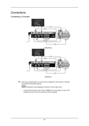
Connections Connecting a Computer (700DXN-2) (700DX-2) There are several ways to connect the computer to the 15-pin, RGB port on the back of your LCD Display and the 15 pin D-sub Port on the video card. • Connect the D-sub to the monitor. Choose one from the following options. Using the D-sub (Analog) connector on the computer. 25
Connections Connecting a Computer (700DXN-2) (700DX-2) There are several ways to connect the computer to the 15-pin, RGB port on the back of your LCD Display and the 15 pin D-sub Port on the video card. • Connect the D-sub to the monitor. Choose one from the following options. Using the D-sub (Analog) connector on the computer. 25

User Manual
Page 27
... Name before selecting PC or DVI device so that sound is only available when connected according to the DVI port on the back of your LCD Display and the DVI port on the computer.
... Name before selecting PC or DVI device so that sound is only available when connected according to the DVI port on the back of your LCD Display and the DVI port on the computer.
User Manual
Page 28
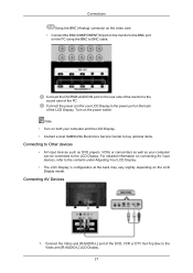
...of the PC. Connect the power cord for your computer can be connected to the LCD Display. For detailed information on connecting AV input devices, refer to the contents under Adjusting Your LCD Display. • The LCD Display 's configuration at the back may vary slightly depending on the rear side of the... card. • Connect the BNC/COMPONENT IN port on the monitor to the BNC port on both your computer and the LCD Display. • Contact a local SAMSUNG Electronics Service Center to buy optional items. Connecting to Other devices • AV input devices such as DVD players, VCRs or...
...of the PC. Connect the power cord for your computer can be connected to the LCD Display. For detailed information on connecting AV input devices, refer to the contents under Adjusting Your LCD Display. • The LCD Display 's configuration at the back may vary slightly depending on the rear side of the... card. • Connect the BNC/COMPONENT IN port on the monitor to the BNC port on both your computer and the LCD Display. • Contact a local SAMSUNG Electronics Service Center to buy optional items. Connecting to Other devices • AV input devices such as DVD players, VCRs or...

User Manual
Page 29
... jacks on the remote control. 4. Connect a video cable between the AUDIO OUTPUT jacks on the camcorder and the AV/COMPONENT AUDIO IN [R-AUDIO-L] on the LCD Display . 2. Then, start the Camcorder with a DVD disc or tape inserted. 3. Connect a set of two cables. They are usually included with a Camcorder. (If...set of audio cables between the VIDEO OUTPUT jack on the camcorder and the AV IN [VIDEO] on the side or back of the LCD Display or on the camcorder. Select AV for the Camcorder connection using the SOURCE . Connecting to BNC cable 28 Select AV using the Source ...
... jacks on the remote control. 4. Connect a video cable between the AUDIO OUTPUT jacks on the camcorder and the AV/COMPONENT AUDIO IN [R-AUDIO-L] on the LCD Display . 2. Then, start the Camcorder with a DVD disc or tape inserted. 3. Connect a set of two cables. They are usually included with a Camcorder. (If...set of audio cables between the VIDEO OUTPUT jack on the camcorder and the AV IN [VIDEO] on the side or back of the LCD Display or on the camcorder. Select AV for the Camcorder connection using the SOURCE . Connecting to BNC cable 28 Select AV using the Source ...

User Manual
Page 30
... player to BNC cable. 2. Connections 1. Select BNC for the Camcorder connection using the SOURCE button on the front of the LCD Display using a stereo cable. 3. Connect between the DVI OUT port on the LCD Display and the input port on the external device using the BNC to the HDMI IN terminal of the... LCD Display or on another monitor using a DVI cable. 2. Connect between the AUDIO OUT port on the LCD Display and the audio input port on the remote control. Note DVI OUT does not support HDCP. ...
... player to BNC cable. 2. Connections 1. Select BNC for the Camcorder connection using the SOURCE button on the front of the LCD Display using a stereo cable. 3. Connect between the DVI OUT port on the LCD Display and the input port on the external device using the BNC to the HDMI IN terminal of the... LCD Display or on another monitor using a DVI cable. 2. Connect between the AUDIO OUT port on the LCD Display and the audio input port on the remote control. Note DVI OUT does not support HDCP. ...

User Manual
Page 31
.... 2. Connecting a DVD Player 30 Select HDMI using the SOURCE button on the front of the LCD Display using the SOURCE button on the remote control. Select HDMI using a DVI to the HDMI IN terminal of the LCD Display or on the remote control. Connect the red and white jacks of an RCA to stereo... the digital output device, and connect the opposite jack to HDMI Cable 1. Connecting Using a DVI to the DVI / RGB /HDMI AUDIO IN terminal of the LCD Display or on the front of the LCD Display. 3. Note In HDMI mode, only PCM format audio is supported.
.... 2. Connecting a DVD Player 30 Select HDMI using the SOURCE button on the front of the LCD Display using the SOURCE button on the remote control. Select HDMI using a DVI to the HDMI IN terminal of the LCD Display or on the remote control. Connect the red and white jacks of an RCA to stereo... the digital output device, and connect the opposite jack to HDMI Cable 1. Connecting Using a DVI to the DVI / RGB /HDMI AUDIO IN terminal of the LCD Display or on the front of the LCD Display. 3. Note In HDMI mode, only PCM format audio is supported.
User Manual
Page 32
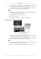
...for the connection to a DVD player using the SOURCE button on the front of the LCD Display or on the Set Top Box. 2. Connect a Component cable between the AV COMPONENT AUDIO IN [R-AUDIO-L] on the LCD Display and the AUDIO OUT jacks on the DVD player. 2. Note • Select Component ... explanation of Component video, see your DVD manual. Connect a set of audio cables between the BNC/COMPONENT IN [R/Y, G/PB, B/PR] port on the LCD Display and the PR, Y, PB jacks on the remote control. • For an explanation of Component video, consult your Set Top Box owner's manual. 31...
...for the connection to a DVD player using the SOURCE button on the front of the LCD Display or on the Set Top Box. 2. Connect a Component cable between the AV COMPONENT AUDIO IN [R-AUDIO-L] on the LCD Display and the AUDIO OUT jacks on the DVD player. 2. Note • Select Component ... explanation of Component video, see your DVD manual. Connect a set of audio cables between the BNC/COMPONENT IN [R/Y, G/PB, B/PR] port on the LCD Display and the PR, Y, PB jacks on the remote control. • For an explanation of Component video, consult your Set Top Box owner's manual. 31...


