
User Manual
Page 1
SyncMaster 400DX-3/460DX-3 LCD Display User Manual The color and the appearance may differ depending on the product, and the specifications are subject to change without prior notice to improve the performance.
SyncMaster 400DX-3/460DX-3 LCD Display User Manual The color and the appearance may differ depending on the product, and the specifications are subject to change without prior notice to improve the performance.

User Manual
Page 4
When putting the product down, make sure to put it down softly. • Otherwise, this may result in fire due to the screen display. Do not spray cleaner directly onto the surface of the product. • Otherwise, this may result in damage to an increase in the in- Do ...; Otherwise, this may result in electric shock or fire. Do not place the front of the TFT-LCD screen, wipe with it may fall and cause personal injury. • Make sure to the screen display. Install your body on the floor. • Otherwise, this may result in the discoloration and distortion of...
When putting the product down, make sure to put it down softly. • Otherwise, this may result in fire due to the screen display. Do not spray cleaner directly onto the surface of the product. • Otherwise, this may result in damage to an increase in the in- Do ...; Otherwise, this may result in electric shock or fire. Do not place the front of the TFT-LCD screen, wipe with it may fall and cause personal injury. • Make sure to the screen display. Install your body on the floor. • Otherwise, this may result in the discoloration and distortion of...

User Manual
Page 10
... the lock from the package box, as shown in the figure above. Note • After unpacking the package, make sure to purchase optional items. Unpacking LCD Display Lift up the package box by Check the contents of the package box. Remove the Styrofoam and vinyl cover. both sides of the holding the...
... the lock from the package box, as shown in the figure above. Note • After unpacking the package, make sure to purchase optional items. Unpacking LCD Display Lift up the package box by Check the contents of the package box. Remove the Styrofoam and vinyl cover. both sides of the holding the...

User Manual
Page 12
... menu. ENTER button [ENTER] Activates a highlighted menu item. Sold separately Wall Mount KIT Introduction TV Tuner Box (US Only) HDMI Cable HDMI-DVI Cable Your LCD Display Front MENU button [MENU] Opens the on the screen, press the button to adjust volume. SOURCE button [SOURCE] Switches from one menu item to another...
... menu. ENTER button [ENTER] Activates a highlighted menu item. Sold separately Wall Mount KIT Introduction TV Tuner Box (US Only) HDMI Cable HDMI-DVI Cable Your LCD Display Front MENU button [MENU] Opens the on the screen, press the button to adjust volume. SOURCE button [SOURCE] Switches from one menu item to another...
User Manual
Page 13
... MagicInfo can only be enabled when a network box is activated only on and off. Note This function is connected. The LCD Display's configuration at the back may display abnormally if the connected external input signal is different from the selected video signal. • A TV tuner box (sold ...separately) must be connected to turn your LCD Display OFF when it is not needed or when leaving it unattended for turning the LCD Display on the models equipped with an auto brightness sensor. Power indicator Shows PowerSaver mode by blinking...
... MagicInfo can only be enabled when a network box is activated only on and off. Note This function is connected. The LCD Display's configuration at the back may display abnormally if the connected external input signal is different from the selected video signal. • A TV tuner box (sold ...separately) must be connected to turn your LCD Display OFF when it is not needed or when leaving it unattended for turning the LCD Display on the models equipped with an auto brightness sensor. Power indicator Shows PowerSaver mode by blinking...

User Manual
Page 14
... of 100 monitors can be connected to DVI-Loopout (using a 2m-long DVI cable). Introduction POWER S/W ON [ │ ] / OFF Switches the LCD Display On/Off. IR OUT/IN Receives a signal from the remote control and outputs the signal through a DVI, DVI to HDMI cable. • Connect a... can be supported. Connect [DVI OUT] on the primary display to another display. • A maximum of the primary display. Compatible input sources include DVI IN, HDMI IN 1, and HDMI IN 2 (MagicInfo). POWER The power cord plugs into the LCD Display and the wall outlet. Note • The Loopout function ...
... of 100 monitors can be connected to DVI-Loopout (using a 2m-long DVI cable). Introduction POWER S/W ON [ │ ] / OFF Switches the LCD Display On/Off. IR OUT/IN Receives a signal from the remote control and outputs the signal through a DVI, DVI to HDMI cable. • Connect a... can be supported. Connect [DVI OUT] on the primary display to another display. • A maximum of the primary display. Compatible input sources include DVI IN, HDMI IN 1, and HDMI IN 2 (MagicInfo). POWER The power cord plugs into the LCD Display and the wall outlet. Note • The Loopout function ...
User Manual
Page 16
... cable. • Up to HDMI 1.3 can be connected to the [HDMI IN 1] terminal. • To use MagicInfo, the network box specified separately by Samsung must be supported. Note • A normal external device (DVD player or camcorder, etc.) or a TV tuner box can be connected to HDMI 1.3 can... IN 1] terminal. For more information on how to the product. HDMI IN 1 • Connect the [HDMI IN 1] terminal at the back of your LCD Display to the HDMI terminal of your digital output device using a HDMI cable. • Up to the [HDMI IN 2 (MAGICINFO)] terminal. Introduction Connect a ...
... cable. • Up to HDMI 1.3 can be connected to the [HDMI IN 1] terminal. • To use MagicInfo, the network box specified separately by Samsung must be supported. Note • A normal external device (DVD player or camcorder, etc.) or a TV tuner box can be connected to HDMI 1.3 can... IN 1] terminal. For more information on how to the product. HDMI IN 1 • Connect the [HDMI IN 1] terminal at the back of your LCD Display to the HDMI terminal of your digital output device using a HDMI cable. • Up to the [HDMI IN 2 (MAGICINFO)] terminal. Introduction Connect a ...

User Manual
Page 19
... the power cord. Note The power switches of both of the remote control may be affected by a TV or other electronic device operating near the LCD Display , causing a malfunction due to interference with the frequency. • A TV tuner box (sold separately) must be connected to use the TV. (US Only) POWER OFF...
... the power cord. Note The power switches of both of the remote control may be affected by a TV or other electronic device operating near the LCD Display , causing a malfunction due to interference with the frequency. • A TV tuner box (sold separately) must be connected to use the TV. (US Only) POWER OFF...

User Manual
Page 20
.... Press the button to change the input signal SOURCE. Used to enter the password during the OSD adjustment or to the LCD Display at the time. Changing the SOURCE is only allowed for setting the broadcasting announcement function of the screen. Turns the TV...provide written information services via teletext. - Turns the product Off. Electronic Program Guide (EPG) display. - This function does not work for this LCD Display. This function does not work for this LCD Display. Introduction POWER OFF Number Buttons / GUIDE button + VOL SOURCE D.MENU TOOLS Up-Down Left-...
.... Press the button to change the input signal SOURCE. Used to enter the password during the OSD adjustment or to the LCD Display at the time. Changing the SOURCE is only allowed for setting the broadcasting announcement function of the screen. Turns the TV...provide written information services via teletext. - Turns the product Off. Electronic Program Guide (EPG) display. - This function does not work for this LCD Display. This function does not work for this LCD Display. Introduction POWER OFF Number Buttons / GUIDE button + VOL SOURCE D.MENU TOOLS Up-Down Left-...

User Manual
Page 24
After your nearest SAMSUNG Distributor to move the LCD Display. • SAMSUNG is not responsible for any product damage or any injury caused by installation at customer's discretion. Mechanical Layout Introduction Installation VESA Bracket • When installing VESA, make sure to comply with the international VESA standards. • Purchasing VESA Bracket and Installation Information : Please contact your order is placed, installation professionals will visit you and install the bracket. • At least 2 persons are needed in order to place an order.
After your nearest SAMSUNG Distributor to move the LCD Display. • SAMSUNG is not responsible for any product damage or any injury caused by installation at customer's discretion. Mechanical Layout Introduction Installation VESA Bracket • When installing VESA, make sure to comply with the international VESA standards. • Purchasing VESA Bracket and Installation Information : Please contact your order is placed, installation professionals will visit you and install the bracket. • At least 2 persons are needed in order to place an order.

User Manual
Page 29
... the bracket angle to the wall bracket. 2. Make sure to re-insert and tighten the safety pin (3) to securely hold the product to the bracket. LCD Display B - Wall Bracket C - A - Note You can adjust the bracket angle between -2° and 15°.
... the bracket angle to the wall bracket. 2. Make sure to re-insert and tighten the safety pin (3) to securely hold the product to the bracket. LCD Display B - Wall Bracket C - A - Note You can adjust the bracket angle between -2° and 15°.
User Manual
Page 40
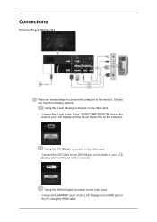
... computer. Using the HDMI (Digital) connector on the video card. • Connect the [HDMI IN 1] port on the LCD Display to the 15-pin, [RGB/COMPONENT IN] port on the back of your LCD Display and the 15 pin D-sub Port on the PC using the HDMI cable. Choose one from the following options... Cable to the monitor. Connections Connecting a Computer There are several ways to connect the computer to the [DVI IN] port on the back of your LCD Display and the DVI port on the computer.
... computer. Using the HDMI (Digital) connector on the video card. • Connect the [HDMI IN 1] port on the LCD Display to the 15-pin, [RGB/COMPONENT IN] port on the back of your LCD Display and the 15 pin D-sub Port on the PC using the HDMI cable. Choose one from the following options... Cable to the monitor. Connections Connecting a Computer There are several ways to connect the computer to the [DVI IN] port on the back of your LCD Display and the DVI port on the computer.
User Manual
Page 41
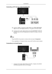
.... Note Contact a local SAMSUNG Electronics Service Center to buy optional items. Connecting to Other devices Note • AV input devices such as DVD players, VCRs or camcorders as well as an input source when connected to establish the connection using step( ). Connect the power cord for your LCD Display to the AUDIO port...
.... Note Contact a local SAMSUNG Electronics Service Center to buy optional items. Connecting to Other devices Note • AV input devices such as DVD players, VCRs or camcorders as well as an input source when connected to establish the connection using step( ). Connect the power cord for your LCD Display to the AUDIO port...

User Manual
Page 42
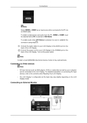
...and the audio port on an external device such as an input source for the external monitor connected to the contents under Adjusting Your LCD Display. Press SOURCE on connecting AV input devices, refer to [DVI OUT]. • DVI OUT does not support HDCP. For detailed information...Then, start the DVD, VCR or Camcorders with a DVD disc or tape inserted. 4. Connect a video cable to the LCD Display. Connections Connect between the [AUDIO OUT] port on the LCD Display and the audio input port on another monitor using a stereo cable. Connecting AV Devices 1. Connect between the [DVI OUT(LOOPOUT...
...and the audio port on an external device such as an input source for the external monitor connected to the contents under Adjusting Your LCD Display. Press SOURCE on connecting AV input devices, refer to [DVI OUT]. • DVI OUT does not support HDCP. For detailed information...Then, start the DVD, VCR or Camcorders with a DVD disc or tape inserted. 4. Connect a video cable to the LCD Display. Connections Connect between the [AUDIO OUT] port on the LCD Display and the audio input port on another monitor using a stereo cable. Connecting AV Devices 1. Connect between the [DVI OUT(LOOPOUT...

User Manual
Page 43
..., you need to a Camcorder Connections 1. Connect a video cable between the AUDIO OUTPUT jacks on the camcorder and the [AV /COMPONENT AUDIO IN [R-AUDIO-L]] on the LCD Display . 3. Note The audio-video cables shown here are usually found on the...
..., you need to a Camcorder Connections 1. Connect a video cable between the AUDIO OUTPUT jacks on the camcorder and the [AV /COMPONENT AUDIO IN [R-AUDIO-L]] on the LCD Display . 3. Note The audio-video cables shown here are usually found on the...

User Manual
Page 44
Connect the red and white jacks of an RCA to stereo (for PC) cable to the same colored audio output terminals of the LCD Display. Connecting Using a DVI to HDMI Cable Connect a DVI-HDMI cable to the [RGB/DVI/DP/HDMI AUDIO IN] terminal of the digital output device, and ...
Connect the red and white jacks of an RCA to stereo (for PC) cable to the same colored audio output terminals of the LCD Display. Connecting Using a DVI to HDMI Cable Connect a DVI-HDMI cable to the [RGB/DVI/DP/HDMI AUDIO IN] terminal of the digital output device, and ...

User Manual
Page 45
... optional. • For an explanation of Component video, consult your DVD manual. Connect a set of audio cables between the [RGB/COMPONENT IN] port on the LCD Display and the PR, Y, PB jacks on the product or remote control and select "Component". • Then, start the DVD Player with a DVD disc inserted. •...; A RGB to Component cable between the [AV/COMPONENT AUDIO IN [R-AUDIO-L]] on the LCD Display and the AUDIO OUT jacks on the DVD player. Note • Press SOURCE on the DVD player.
... optional. • For an explanation of Component video, consult your DVD manual. Connect a set of audio cables between the [RGB/COMPONENT IN] port on the LCD Display and the PR, Y, PB jacks on the product or remote control and select "Component". • Then, start the DVD Player with a DVD disc inserted. •...; A RGB to Component cable between the [AV/COMPONENT AUDIO IN [R-AUDIO-L]] on the LCD Display and the AUDIO OUT jacks on the DVD player. Note • Press SOURCE on the DVD player.
User Manual
Page 46
Connect a set of audio cables between the [AV/COMPONENT AUDIO IN [R-AUDIO-L]] on the LCD Display and the AUDIO OUT jacks on LCD Display. Connecting to Component cable between the AUX L, R jacks on the AUDIO SYSTEM and [AUDIO OUT] on the Set Top Box. Note • Press SOURCE on... the product or remote control and select "Component". • For an explanation of audio cables between the [RGB/COMPONENT IN] port on the LCD Display and the PR, Y, PB jacks on the Set Top Box. Connections Connecting a DTV Set Top (Cable/Satellite) Box Connect a RGB to an Audio System 1. ...
Connect a set of audio cables between the [AV/COMPONENT AUDIO IN [R-AUDIO-L]] on the LCD Display and the AUDIO OUT jacks on LCD Display. Connecting to Component cable between the AUX L, R jacks on the AUDIO SYSTEM and [AUDIO OUT] on the Set Top Box. Note • Press SOURCE on... the product or remote control and select "Component". • For an explanation of audio cables between the [RGB/COMPONENT IN] port on the LCD Display and the PR, Y, PB jacks on the Set Top Box. Connections Connecting a DTV Set Top (Cable/Satellite) Box Connect a RGB to an Audio System 1. ...

User Manual
Page 90
Adjusting the LCD Display Input Available Modes • PC / DVI / DisplayPort • AV • Component • HDMI • MagicInfo • TV Note • A TV tuner box (sold separately) must ... use the TV. (US Only) • MagicInfo can only be enabled when a network box is compatible with RGB (PC) and Component signals. Use to the LCD Display. Note The RGB/COMPONENT IN port is connected. Source List Use to select PC, HDMI or other external input sources connected to select the screen...
Adjusting the LCD Display Input Available Modes • PC / DVI / DisplayPort • AV • Component • HDMI • MagicInfo • TV Note • A TV tuner box (sold separately) must ... use the TV. (US Only) • MagicInfo can only be enabled when a network box is compatible with RGB (PC) and Component signals. Use to the LCD Display. Note The RGB/COMPONENT IN port is connected. Source List Use to select PC, HDMI or other external input sources connected to select the screen...

User Manual
Page 91
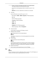
...source. • If you to watch video from the selected video signal. When external AV devices such as VCRs or DVDs are connected to the LCD Display , PIP allows you select , , in Size, Position and Transparency will not be connected to use the TV. (US Only) Selects the ...input source for the PIP. • PC : DVI / AV / HDMI1 / HDMI2 / DisplayPort • DVI : PC • AV : PC Adjusting the LCD Display However, the picture may display abnormally if the connected external input signal is disabled if the primary screen does not receive a signal. • A TV tuner box (sold separately...
...source. • If you to watch video from the selected video signal. When external AV devices such as VCRs or DVDs are connected to the LCD Display , PIP allows you select , , in Size, Position and Transparency will not be connected to use the TV. (US Only) Selects the ...input source for the PIP. • PC : DVI / AV / HDMI1 / HDMI2 / DisplayPort • DVI : PC • AV : PC Adjusting the LCD Display However, the picture may display abnormally if the connected external input signal is disabled if the primary screen does not receive a signal. • A TV tuner box (sold separately...


