User Manual (user Manual) (ver.1.0) (English)
Page 5
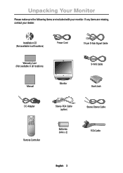
Installation CD (Not available in all locations) Power Cord 15-pin D-Sub Signal Cable Warranty Card (Not available in all locations) Manual PC V1 V2 TV Source PIP Exit Menu SyncMaster 150MB VOL Monitor S-VHS Cable Scart Jack DC Adapter Stereo-RCA Cable (option) Stereo-Stereo Cable Remote Controller Batteries (AAA x 2) RCA Cable English 3 If any items are included with your dealer. Unpacking Your Monitor Please make sure the following items are missing, contact your monitor.
Installation CD (Not available in all locations) Power Cord 15-pin D-Sub Signal Cable Warranty Card (Not available in all locations) Manual PC V1 V2 TV Source PIP Exit Menu SyncMaster 150MB VOL Monitor S-VHS Cable Scart Jack DC Adapter Stereo-RCA Cable (option) Stereo-Stereo Cable Remote Controller Batteries (AAA x 2) RCA Cable English 3 If any items are included with your dealer. Unpacking Your Monitor Please make sure the following items are missing, contact your monitor.
User Manual (user Manual) (ver.1.0) (English)
Page 7
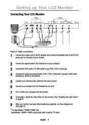
... to the DC adapter and connect the adapter jack to the DC12V power port on the back of your monitor. 2 Connect the signal cable to the video port on your computer. 3 Connect the RCA cable or S-VHS cable to your DVD, VCR or camcoder. 4 Connect the audio sources(computer, DVD, ...monitor. (See "Installing the video driver" on page 6) 9 After your monitor has been fully installed successfully, run Auto-Adjustment. (See page12) * For SyncMaster 150MP/170MP only (SyncMaster 150MP/170MP are products with a built-in TV tuner) English 5 Setting up Your LCD Monitor Connecting Your LCD Monitor Figure 3.
... to the DC adapter and connect the adapter jack to the DC12V power port on the back of your monitor. 2 Connect the signal cable to the video port on your computer. 3 Connect the RCA cable or S-VHS cable to your DVD, VCR or camcoder. 4 Connect the audio sources(computer, DVD, ...monitor. (See "Installing the video driver" on page 6) 9 After your monitor has been fully installed successfully, run Auto-Adjustment. (See page12) * For SyncMaster 150MP/170MP only (SyncMaster 150MP/170MP are products with a built-in TV tuner) English 5 Setting up Your LCD Monitor Connecting Your LCD Monitor Figure 3.

User Manual (user Manual) (ver.1.0) (English)
Page 8
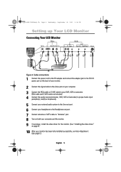
... the computer. 3 Turn on . It allows you to check whether your PC system needs a video driver, follow the instructions given below : Power Indicator Figure 4. Make sure that PC is selected as a primary source by following the steps given below according to use with your CD package ...necessary drivers for more information. If your computer and the monitor. 2 Unplug the video cable from the back of the new VESA® Plug and Play solution eliminates complicated and time consuming setup. Power Indicator 1 Turn off both your monitor and computer are properly connected but the monitor ...
... the computer. 3 Turn on . It allows you to check whether your PC system needs a video driver, follow the instructions given below : Power Indicator Figure 4. Make sure that PC is selected as a primary source by following the steps given below according to use with your CD package ...necessary drivers for more information. If your computer and the monitor. 2 Unplug the video cable from the back of the new VESA® Plug and Play solution eliminates complicated and time consuming setup. Power Indicator 1 Turn off both your monitor and computer are properly connected but the monitor ...

User Manual (user Manual) (ver.1.0) (English)
Page 10
... of the control button indicate currently active Video source. PC V1 V2 PIP Source PIP Exit Menu VOL * 17" : SyncMaster 170MB Figure 6. Name 1 Source 2 PIP 3 Exit 4 Menu 5 Power Description n Selects Video source. n PIP off . n Exits from the OSD system. n Turns ON/OFF the monitor.... English 8 n PIP to easily adjust the characteristics of the monitor. -Green : Normal Operation. -Amber : Power Saving Mode or Disconnected Signal Cable. n Turns the PIP off . User control locations No. n Exits from menus and sub-menus. n Opens the OSD and selects...
... of the control button indicate currently active Video source. PC V1 V2 PIP Source PIP Exit Menu VOL * 17" : SyncMaster 170MB Figure 6. Name 1 Source 2 PIP 3 Exit 4 Menu 5 Power Description n Selects Video source. n PIP off . n Exits from the OSD system. n Turns ON/OFF the monitor.... English 8 n PIP to easily adjust the characteristics of the monitor. -Green : Normal Operation. -Amber : Power Saving Mode or Disconnected Signal Cable. n Turns the PIP off . User control locations No. n Exits from menus and sub-menus. n Opens the OSD and selects...

User Manual (user Manual) (ver.1.0) (English)
Page 22
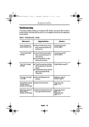
...may be able to n Adjust the Coarse function and flicker, jitter or then adjust the Fine function. Suggested Actions Reference Screen is blank and power indicator is on . Contrast, page 12. shimmer on the image Image Lock, Fine, page 12 ~13. Display Modes, page 26. The image is...;rmly connected to the PC or video sources. to your problem. Table 3. Image Lock, Coarse, page 12~13. n Ensure that the signal cable is too light n Adjust the Brightness and or too dark Contrast. Horizontal bars appear n Adjust the Fine function. " Check Signal...
...may be able to n Adjust the Coarse function and flicker, jitter or then adjust the Fine function. Suggested Actions Reference Screen is blank and power indicator is on . Contrast, page 12. shimmer on the image Image Lock, Fine, page 12 ~13. Display Modes, page 26. The image is...;rmly connected to the PC or video sources. to your problem. Table 3. Image Lock, Coarse, page 12~13. n Ensure that the signal cable is too light n Adjust the Brightness and or too dark Contrast. Horizontal bars appear n Adjust the Fine function. " Check Signal...

User Manual (user Manual) (ver.1.0) (English)
Page 30
... maximum tilt angle is restricted to the mechanical part of the stand. If possible, use flammable cleaning material to the cable connectors as explained below: Unplug the monitor from the power outlet before cleaning. n To clean your LCD monitor or any other than specified range may give more stability...
... maximum tilt angle is restricted to the mechanical part of the stand. If possible, use flammable cleaning material to the cable connectors as explained below: Unplug the monitor from the power outlet before cleaning. n To clean your LCD monitor or any other than specified range may give more stability...

User Manual (user Manual) (ver.1.0) (English)
Page 32
...OSD Lock/Unlock 10 OSD Control 17 P Pan 16 Pin Assignments 25 PIP 8, 14 Plug and Play 6 Power 8 Power Indicator 6 Power-saving modes 19 R Remote Controller 3, 18 Reset 13 S S-VHS Cable 3 Safety Instructions 2 Scart Jack 3 Screen controls 12 Self-test feature check 6 Sharpness 15 Size 14 ...Source 8, 15 Speaker mute 15 Stereo-RCA Cable 3 T Tilt the screen 4 Timer 16 Treble 15 Troubleshooting 20 U User control locations...
...OSD Lock/Unlock 10 OSD Control 17 P Pan 16 Pin Assignments 25 PIP 8, 14 Plug and Play 6 Power 8 Power Indicator 6 Power-saving modes 19 R Remote Controller 3, 18 Reset 13 S S-VHS Cable 3 Safety Instructions 2 Scart Jack 3 Screen controls 12 Self-test feature check 6 Sharpness 15 Size 14 ...Source 8, 15 Speaker mute 15 Stereo-RCA Cable 3 T Tilt the screen 4 Timer 16 Treble 15 Troubleshooting 20 U User control locations...

User Manual (user Manual) (ver.1.0) (English)
Page 33
.... You may cause undesired operation. It may cause harmful interference to radio communications. For 120 Volt applications, use only UL Listed detachable power cord with similar configuration. n Connect the equipment into an outlet on , the user is connected. For 240 Volt applications ...use shielded signal interface cables to maintain FCC compliance for product compliance: SAMSUNG ELECTRONICS CO., LTD America QA Lab of Samsung 85 West Tasman Drive San Jose, CA 95134 USA Tel) 408-544-5124 Fax) ...
.... You may cause undesired operation. It may cause harmful interference to radio communications. For 120 Volt applications, use only UL Listed detachable power cord with similar configuration. n Connect the equipment into an outlet on , the user is connected. For 240 Volt applications ...use shielded signal interface cables to maintain FCC compliance for product compliance: SAMSUNG ELECTRONICS CO., LTD America QA Lab of Samsung 85 West Tasman Drive San Jose, CA 95134 USA Tel) 408-544-5124 Fax) ...

User Manual (user Manual) (ver.1.0) (English)
Page 5
.... Installation CD (Not available in all locations) Power Cord 15-pin D-Sub Signal Cable Warranty Card (Not available in all locations) Manual PC V1 V2 TV Source PIP Exit Menu SyncMaster 150MP CH VOL Monitor DC Adapter Stereo-RCA Cable (option) Scart Jack 1 2 3 4 5 6 7 8 9 Display 0 Pre.CH Stereo-Stereo Cable Batteries (AAA x 2) Remote Controller PAL-NTSC...
.... Installation CD (Not available in all locations) Power Cord 15-pin D-Sub Signal Cable Warranty Card (Not available in all locations) Manual PC V1 V2 TV Source PIP Exit Menu SyncMaster 150MP CH VOL Monitor DC Adapter Stereo-RCA Cable (option) Scart Jack 1 2 3 4 5 6 7 8 9 Display 0 Pre.CH Stereo-Stereo Cable Batteries (AAA x 2) Remote Controller PAL-NTSC...
User Manual (user Manual) (ver.1.0) (English)
Page 7
...adapter and connect the adapter jack to the DC12V power port on the back of your monitor. 2 Connect the signal cable to the video port on your computer. 3 Connect the RCA cable or S-VHS cable to your DVD, VCR or camcoder. (RCA cable and S-VHS cable not included) 4 Connect the audio sources(computer,...Ain(stereo)). 5 Connect your external audio system to the Line-out port. 6 Connect your headphone to the Headphone-out port. 7 Connect antenna or CATV cable to "Antenna" port. 8 Turn on both your computer and the monitor. 9 If necessary, install the video driver for the monitor. (See "Installing the...
...adapter and connect the adapter jack to the DC12V power port on the back of your monitor. 2 Connect the signal cable to the video port on your computer. 3 Connect the RCA cable or S-VHS cable to your DVD, VCR or camcoder. (RCA cable and S-VHS cable not included) 4 Connect the audio sources(computer,...Ain(stereo)). 5 Connect your external audio system to the Line-out port. 6 Connect your headphone to the Headphone-out port. 7 Connect antenna or CATV cable to "Antenna" port. 8 Turn on both your computer and the monitor. 9 If necessary, install the video driver for the monitor. (See "Installing the...
User Manual (user Manual) (ver.1.0) (English)
Page 8
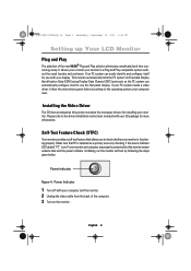
... properly. It allows you to check whether your monitor and computer are properly connected but the monitor screen remains dark and the power indicator is on the monitor. Make sure that allows you to the driver installation instructions included with your monitor. Your PC system... 1 Turn off both your PC system needs a video driver, follow the instructions given below : Power Indicator Figure 4. English 6 If your computer and the monitor. 2 Unplug the video cable from the back of the new VESA® Plug and Play solution eliminates complicated and time consuming setup. Self-...
... properly. It allows you to check whether your monitor and computer are properly connected but the monitor screen remains dark and the power indicator is on the monitor. Make sure that allows you to the driver installation instructions included with your monitor. Your PC system... 1 Turn off both your PC system needs a video driver, follow the instructions given below : Power Indicator Figure 4. English 6 If your computer and the monitor. 2 Unplug the video cable from the back of the new VESA® Plug and Play solution eliminates complicated and time consuming setup. Self-...
User Manual (user Manual) (ver.1.0) (English)
Page 10
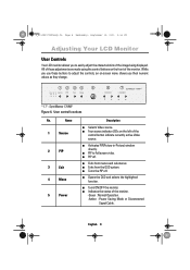
...CH VOL * 17" : SyncMaster 170MP Figure 6. User control locations No. I PIP off . I Exits from menus and sub-menus. I Turns the PIP off . I Indicates the status of the image being displayed. I PIP to easily adjust the characteristics of the monitor. -Green : Normal Operation. -Amber : Power Saving Mode or Disconnected Signal Cable. I Four source indicator ...made using the control buttons on the left of the monitor. While you their numeric values as they change. Name 1 Source 2 PIP 3 Exit 4 Menu 5 Power Description I Exits from the OSD system.
...CH VOL * 17" : SyncMaster 170MP Figure 6. User control locations No. I PIP off . I Exits from menus and sub-menus. I Turns the PIP off . I Indicates the status of the image being displayed. I PIP to easily adjust the characteristics of the monitor. -Green : Normal Operation. -Amber : Power Saving Mode or Disconnected Signal Cable. I Four source indicator ...made using the control buttons on the left of the monitor. While you their numeric values as they change. Name 1 Source 2 PIP 3 Exit 4 Menu 5 Power Description I Exits from the OSD system.
User Manual (user Manual) (ver.1.0) (English)
Page 24
... adaptor. Brightness, page 12. Vertical bars appear to solve it yourself. English 22 Suggested Actions Reference Screen is blank and power indicator is on . Connecting your problem. Display Modes, page 28. Connecting your LCD monitor, you may be able to I Ensure ...values with the data in the Display Modes Timing Chart. " Check Signal Cable" message I Adjust the Fine function. Image Lock, Coarse, page 12~13. Troubleshooting - "Sync. Horizontal bars appear I Ensure that the power cord is firmly connected and the LCD monitor is off I Adjust...
... adaptor. Brightness, page 12. Vertical bars appear to solve it yourself. English 22 Suggested Actions Reference Screen is blank and power indicator is on . Connecting your problem. Display Modes, page 28. Connecting your LCD monitor, you may be able to I Ensure ...values with the data in the Display Modes Timing Chart. " Check Signal Cable" message I Adjust the Fine function. Image Lock, Coarse, page 12~13. Troubleshooting - "Sync. Horizontal bars appear I Ensure that the power cord is firmly connected and the LCD monitor is off I Adjust...
User Manual (user Manual) (ver.1.0) (English)
Page 33
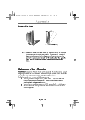
... dampened with water or mild detergent. Users cannot service the monitor. If possible, use flammable cleaning material to the cable connectors as explained below: Unplug the monitor from the power outlet before cleaning. The maximum tilt angle is restricted to cleaning as described on page 5). Maintenance of Your LCD monitor WARNING...
... dampened with water or mild detergent. Users cannot service the monitor. If possible, use flammable cleaning material to the cable connectors as explained below: Unplug the monitor from the power outlet before cleaning. The maximum tilt angle is restricted to cleaning as described on page 5). Maintenance of Your LCD monitor WARNING...
User Manual (user Manual) (ver.1.0) (English)
Page 35
...PAL-NTSC connector 3 PAL Broadcasting System 29 Pan 17 Pin Assignments 27 PIP 8, 14 Plug and Play 6 Power 8 Power Indicator 6 Power-saving modes 21 Program 10 R Remote Controller 3, 19 Reset 13 S S-VHS Cable 3 Safety Instructions 2 Scart Jack 3 Screen controls 12 Self-test feature check 6 Sharpness 16 Size 14 ...Source 8, 17 Speaker mute 17 Stereo-RCA Cable 3 Stereo System 15 Store 16 T Tilt the screen 4 Timer...
...PAL-NTSC connector 3 PAL Broadcasting System 29 Pan 17 Pin Assignments 27 PIP 8, 14 Plug and Play 6 Power 8 Power Indicator 6 Power-saving modes 21 Program 10 R Remote Controller 3, 19 Reset 13 S S-VHS Cable 3 Safety Instructions 2 Scart Jack 3 Screen controls 12 Self-test feature check 6 Sharpness 16 Size 14 ...Source 8, 17 Speaker mute 17 Stereo-RCA Cable 3 Stereo System 15 Store 16 T Tilt the screen 4 Timer...

User Manual (user Manual) (ver.1.0) (English)
Page 36
...Samsung 85 West Tasman Drive San Jose, CA 95134 USA Tel) 408-544-5124 Fax) 408-544-5191 Provided with this device must use shielded signal interface cables to any interference received, including interference that the ampere rating of the FCC Rules. For 120 Volt applications, use only UL Listed Detachable power... and magnetic fields. I Reorient or relocate the receiving antenna. For 240 Volt applications use only UL Listed detachable power cord with SWEDAC(MPR II) recommendations for help. Voltage Fluctuations I EN50082-1 : 1992 - These limits are designed to ...
...Samsung 85 West Tasman Drive San Jose, CA 95134 USA Tel) 408-544-5124 Fax) 408-544-5191 Provided with this device must use shielded signal interface cables to any interference received, including interference that the ampere rating of the FCC Rules. For 120 Volt applications, use only UL Listed Detachable power... and magnetic fields. I Reorient or relocate the receiving antenna. For 240 Volt applications use only UL Listed detachable power cord with SWEDAC(MPR II) recommendations for help. Voltage Fluctuations I EN50082-1 : 1992 - These limits are designed to ...


