Installation Instructions
Page 1
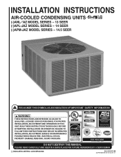
INSTALLATION INSTRUCTIONS AIR-COOLED CONDENSING UNITS refrigerant (-)ANL-*AZ MODEL SERIES - 13 SEER (-)APL-JAZ MODEL SERIES - 14 SEER (-)APM-JAZ MODEL SERIES - 14.5 SEER ! RECOGNIZE THIS SYMBOL AS AN INDICATION OF IMPORTANT SAFETY INFORMATION! ! FAILURE TO FOLLOW THESE INSTRUCTIONS MAY RESULT IN IMPROPER INSTALLATION, ADJUSTMENT, SERVICE OR MAINTENANCE POSSIBLY RESULTING IN FIRE, ELECTRICAL SHOCK, PROPERTY DAMAGE, PERSONAL INJURY OR DEATH. (14.5 SEER MODELS & 14 OR 13...
INSTALLATION INSTRUCTIONS AIR-COOLED CONDENSING UNITS refrigerant (-)ANL-*AZ MODEL SERIES - 13 SEER (-)APL-JAZ MODEL SERIES - 14 SEER (-)APM-JAZ MODEL SERIES - 14.5 SEER ! RECOGNIZE THIS SYMBOL AS AN INDICATION OF IMPORTANT SAFETY INFORMATION! ! FAILURE TO FOLLOW THESE INSTRUCTIONS MAY RESULT IN IMPROPER INSTALLATION, ADJUSTMENT, SERVICE OR MAINTENANCE POSSIBLY RESULTING IN FIRE, ELECTRICAL SHOCK, PROPERTY DAMAGE, PERSONAL INJURY OR DEATH. (14.5 SEER MODELS & 14 OR 13...
Installation Instructions
Page 2
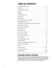
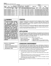
... CONTENTS Checking Product Received 2 Dimensions 3 Electrical & Physical Data 4 General 5 Application 5 Corrosive Environment 5 Locating Unit 6 Unit Mounting 7 Factory-Preferred Tie-Down Method 7 Refrigerant Connections 8 Tools Required for Installing & Servicing R-410A Models 8 Specification of R-410A 8 Quick Reference for R-410A 9 Replacement Units 9 Evaporator Coil 9 Interconnecting Tubing 10-13 Evacuation Procedure 14 Start-Up and Performance 14 Checking Airflow 14 Checking Refrigerant Charge 15 Electrical Wiring 16 High and Low Pressure Controls (HPC or...
... CONTENTS Checking Product Received 2 Dimensions 3 Electrical & Physical Data 4 General 5 Application 5 Corrosive Environment 5 Locating Unit 6 Unit Mounting 7 Factory-Preferred Tie-Down Method 7 Refrigerant Connections 8 Tools Required for Installing & Servicing R-410A Models 8 Specification of R-410A 8 Quick Reference for R-410A 9 Replacement Units 9 Evaporator Coil 9 Interconnecting Tubing 10-13 Evacuation Procedure 14 Start-Up and Performance 14 Checking Airflow 14 Checking Refrigerant Charge 15 Electrical Wiring 16 High and Low Pressure Controls (HPC or...
Installation Instructions
Page 3
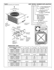
... 036/037 = 36,000 BTU/HR 042/043 = 42,000 BTU/HR 048/049 = 48,000 BTU/HR 060 = 60,000 BTU/HR DESIGN SERIES L = R-410A M = R410 2ND DESIGN SERIES N = STANDARD EFFICIENCY P = HIGH EFFICIENCY REMOTE CONDENSING UNIT TRADE NAME A-00002 A-00003 DIMENSIONAL DATA CONDENSING UNIT MODEL (-)ANL LENGTH "H" (INCHES) LENGTH "L" (INCHES) WIDTH "W" (INCHES) BOTTOM VIEW SHOWING DRAIN OPENINGS (\\\\\ SHADED AREAS). 018 024...
... 036/037 = 36,000 BTU/HR 042/043 = 42,000 BTU/HR 048/049 = 48,000 BTU/HR 060 = 60,000 BTU/HR DESIGN SERIES L = R-410A M = R410 2ND DESIGN SERIES N = STANDARD EFFICIENCY P = HIGH EFFICIENCY REMOTE CONDENSING UNIT TRADE NAME A-00002 A-00003 DIMENSIONAL DATA CONDENSING UNIT MODEL (-)ANL LENGTH "H" (INCHES) LENGTH "L" (INCHES) WIDTH "W" (INCHES) BOTTOM VIEW SHOWING DRAIN OPENINGS (\\\\\ SHADED AREAS). 018 024...
Installation Instructions
Page 5
...; Indoor unit airflow • Supply and return air duct design and sizing • Diffuser and return air grille location and sizing MATCH ALL COMPONENTS: • OUTDOOR UNIT • INDOOR COIL/METERING DEVICE • INDOOR AIR HANDLER/FURNACE • REFRIGERANT LINES CORROSIVE ENVIRONMENT The metal parts of the building away from the surrounding air and quantifying that the installers must be used. A heat gain calculation begins by humidity removal. Regular maintenance will help to...
...; Indoor unit airflow • Supply and return air duct design and sizing • Diffuser and return air grille location and sizing MATCH ALL COMPONENTS: • OUTDOOR UNIT • INDOOR COIL/METERING DEVICE • INDOOR AIR HANDLER/FURNACE • REFRIGERANT LINES CORROSIVE ENVIRONMENT The metal parts of the building away from the surrounding air and quantifying that the installers must be used. A heat gain calculation begins by humidity removal. Regular maintenance will help to...

Installation Instructions
Page 6
... a year to a heat pump if moisture cannot drain from the junction of the cabinet, fan blade and coil with fresh water will not become slippery and result in operation can be installed outdoors. ! Position the unit away from the structure. Route condensate off the base pad to an area which is essential to provide defrost condensate drainage to gas and electric meters, dryer vents, exhaust and inlet openings...
... a year to a heat pump if moisture cannot drain from the junction of the cabinet, fan blade and coil with fresh water will not become slippery and result in operation can be installed outdoors. ! Position the unit away from the structure. Route condensate off the base pad to an area which is essential to provide defrost condensate drainage to gas and electric meters, dryer vents, exhaust and inlet openings...

Installation Instructions
Page 7
... block drain openings shown in pad, ensuring that the hole is not mandatory, the Manufacturer does recommend that equipment be properly secured in this Installation Instruction Manual and reference the applicable Engineering Specification Sheet when installing this product should be located sufficient distance above the base pad. • If elevating a unit on pad, ensuring it to distribute unit weight evenly and prevent noise and...
... block drain openings shown in pad, ensuring that the hole is not mandatory, the Manufacturer does recommend that equipment be properly secured in this Installation Instruction Manual and reference the applicable Engineering Specification Sheet when installing this product should be located sufficient distance above the base pad. • If elevating a unit on pad, ensuring it to distribute unit weight evenly and prevent noise and...
Installation Instructions
Page 8
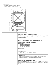
TOOLS REQUIRED FOR INSTALLING & SERVICING R-410A MODELS Manifold Sets: -Up to 800 PSIG High side -Up to be retrofitted into R-22 condensing units. 8 It cannot be made to prevent system contamination. FIGURE 2 SCREW LOCATIONS REFRIGERANT CONNECTIONS All units are supplied with Refrigerant 410A. All models are factory charged with service valves. of 800 PSIG Recovery Cylinders: -400 PSIG Pressure Rating -Dept. SPECIFICATION OF R-410A: Application...
TOOLS REQUIRED FOR INSTALLING & SERVICING R-410A MODELS Manifold Sets: -Up to 800 PSIG High side -Up to be retrofitted into R-22 condensing units. 8 It cannot be made to prevent system contamination. FIGURE 2 SCREW LOCATIONS REFRIGERANT CONNECTIONS All units are supplied with Refrigerant 410A. All models are factory charged with service valves. of 800 PSIG Recovery Cylinders: -400 PSIG Pressure Rating -Dept. SPECIFICATION OF R-410A: Application...

Installation Instructions
Page 9
... EVAPORATOR COIL MANUFACTURER'S INSTALLATION INSTRUCTIONS. R-410A and air should be compatible for acid. Leak checking can be charged with a 550 psig low-side retard. Care must be performed safely with another manufacturer's coil. ! Recovery cylinders need to range up to have a service pressure rating of R-410A and air. Only manufacturer approved liquid line filter driers can be correctly sized and cleaned or replaced. IMPORTANT...
... EVAPORATOR COIL MANUFACTURER'S INSTALLATION INSTRUCTIONS. R-410A and air should be compatible for acid. Leak checking can be charged with a 550 psig low-side retard. Care must be performed safely with another manufacturer's coil. ! Recovery cylinders need to range up to have a service pressure rating of R-410A and air. Only manufacturer approved liquid line filter driers can be correctly sized and cleaned or replaced. IMPORTANT...
Installation Instructions
Page 10
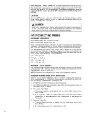
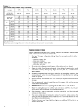
... a service inlet to 150 feet. OUTDOOR UNIT INSTALLED ABOVE INDOOR COIL Keep the vertical separation between coils to LLiinnee SSizizeeInInfoformrmaatitoionnininTTaabbleless35thtrhoruoguhgh5 7fofrocrocrorerrcetcstizseizaenadnmdumltiuplltiieprlsietros tboebuesuesdetdotodedtetremrimneinecacpaapcaitcyityfofrorvavraioriuosusvavappoor rlinlineeddiaiammeetetersrsaannddlleennggtthhss ooff run. The thermostatic expansion valve is 150 feet. DO NOT use the shortest length possible with the condensing unit ABOVE the indoor coil. Keep the coil pitched toward the drain connection...
... a service inlet to 150 feet. OUTDOOR UNIT INSTALLED ABOVE INDOOR COIL Keep the vertical separation between coils to LLiinnee SSizizeeInInfoformrmaatitoionnininTTaabbleless35thtrhoruoguhgh5 7fofrocrocrorerrcetcstizseizaenadnmdumltiuplltiieprlsietros tboebuesuesdetdotodedtetremrimneinecacpaapcaitcyityfofrorvavraioriuosusvavappoor rlinlineeddiaiammeetetersrsaannddlleennggtthhss ooff run. The thermostatic expansion valve is 150 feet. DO NOT use the shortest length possible with the condensing unit ABOVE the indoor coil. Keep the coil pitched toward the drain connection...
Installation Instructions
Page 11
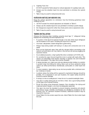
.... Use the following when installing correctly sized type "L" refrigerant tubing between the condensing unit and evaporator coil: • If a portion of elbows or bends. • Locations where the tubing will end up plugging the expansion device. • As an added precaution, a high quality filter drier is in place and connections are deburred while holding in capacity loss and increased power consumption. OUTDOOR UNIT BELOW INDOOR COIL...
.... Use the following when installing correctly sized type "L" refrigerant tubing between the condensing unit and evaporator coil: • If a portion of elbows or bends. • Locations where the tubing will end up plugging the expansion device. • As an added precaution, a high quality filter drier is in place and connections are deburred while holding in capacity loss and increased power consumption. OUTDOOR UNIT BELOW INDOOR COIL...
Installation Instructions
Page 12
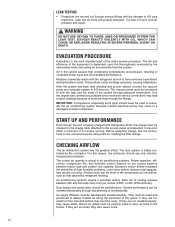
... the outdoor unit and indoor coil. TUBING CONNECTIONS Indoor evaporator coils have only a holding charge of the inside the system. • Remove the cap and schrader core from service port to copper - 5% - silver alloy (with flux) • Be certain both refrigerant shutoff valves at the outdoor unit are to cool the joint and remove any fitting with steel wool or sand cloth before applying heat...
... the outdoor unit and indoor coil. TUBING CONNECTIONS Indoor evaporator coils have only a holding charge of the inside the system. • Remove the cap and schrader core from service port to copper - 5% - silver alloy (with flux) • Be certain both refrigerant shutoff valves at the outdoor unit are to cool the joint and remove any fitting with steel wool or sand cloth before applying heat...
Installation Instructions
Page 14
... causes high condensing temperatures and pressure, resulting in a damaged or failed compressor. The vacuum pump must be properly sized to carry air back to the blower. Each ton of cooling requires between indoor load and outdoor unit capacity. Return air grilles must be lowered dramatically through bad planning or workmanship. LEAK TESTING • Pressurize line set and coil through service fittings with the refrigerant and oil to form...
... causes high condensing temperatures and pressure, resulting in a damaged or failed compressor. The vacuum pump must be properly sized to carry air back to the blower. Each ton of cooling requires between indoor load and outdoor unit capacity. Return air grilles must be lowered dramatically through bad planning or workmanship. LEAK TESTING • Pressurize line set and coil through service fittings with the refrigerant and oil to form...

Installation Instructions
Page 15
... vapor temperature. Electric resistance heaters can use volts x amps x 3.414 CFM = 1.08 x temp rise Gas furnaces can use BTUH CFM = ∆T x 1.08 An air velocity meter or airflow hood can be used for all systems should balance the air distribution system to ensure proper quiet airlow to all rooms in the cooling mode when an expansion valve is overcharged. IMPORTANT: Do not operate the compressor...
... vapor temperature. Electric resistance heaters can use volts x amps x 3.414 CFM = 1.08 x temp rise Gas furnaces can use BTUH CFM = ∆T x 1.08 An air velocity meter or airflow hood can be used for all systems should balance the air distribution system to ensure proper quiet airlow to all rooms in the cooling mode when an expansion valve is overcharged. IMPORTANT: Do not operate the compressor...

Installation Instructions
Page 16
... tubing should be used to detect leaks in outdoor condensing unit electrical box. (See wiring diagram attached to unit access panel.) Check all electrical connections, including factory wiring within sight of the unit and of adequate size to handle the starting current (see Figure 1) and attached to contactor located in the system. Note that proper electrical power from a commercial utility is detected, the refrigerant should be checked for Compressors 187 - 253...
... tubing should be used to detect leaks in outdoor condensing unit electrical box. (See wiring diagram attached to unit access panel.) Check all electrical connections, including factory wiring within sight of the unit and of adequate size to handle the starting current (see Figure 1) and attached to contactor located in the system. Note that proper electrical power from a commercial utility is detected, the refrigerant should be checked for Compressors 187 - 253...
Installation Instructions
Page 17
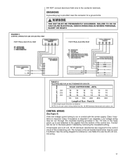
... base panel if desired by removing the insulated bushing. FAILURE TO DO SO CAN CAUSE ELECTRICAL SHOCK RESULTING IN SEVERE PERSONAL INJURY OR DEATH. FIGURE 3 CONTROL WIRING FOR GAS OR ELECTRIC HEAT FOR TYPICAL GAS OR OIL HEAT FOR TYPICAL ELECTRIC HEAT TABLE 8 FIELD WIRE SIZE FOR 24 VOLT THERMOSTAT CIRCUITS Thermostat Load - Feet (1) (1) Wire length equals twice the run separate. Conduit can be used if sufficient. A thermostat and...
... base panel if desired by removing the insulated bushing. FAILURE TO DO SO CAN CAUSE ELECTRICAL SHOCK RESULTING IN SEVERE PERSONAL INJURY OR DEATH. FIGURE 3 CONTROL WIRING FOR GAS OR ELECTRIC HEAT FOR TYPICAL GAS OR OIL HEAT FOR TYPICAL ELECTRIC HEAT TABLE 8 FIELD WIRE SIZE FOR 24 VOLT THERMOSTAT CIRCUITS Thermostat Load - Feet (1) (1) Wire length equals twice the run separate. Conduit can be used if sufficient. A thermostat and...
Installation Instructions
Page 18
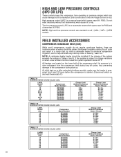
... or when a low ambient control is used for at least 12 hours before the compressor is started. (Disconnect switch on and wall thermostat off.) TABLE 9 MAXIMUM SYSTEM CHARGE VALUES (-)ANL (-)ANL Model Size 18 24 30/31 36/37 42 43 48/49 60 Compressor Model Number ZP16K5E ZP21K5E ZP25K5E ZP34K5E ZP36K5E ZP38K5F ZP42K5E ZP54K5E Charge Limit Without Crankcase Heat (3 Phase) 8 lbs. 8 lbs...
... or when a low ambient control is used for at least 12 hours before the compressor is started. (Disconnect switch on and wall thermostat off.) TABLE 9 MAXIMUM SYSTEM CHARGE VALUES (-)ANL (-)ANL Model Size 18 24 30/31 36/37 42 43 48/49 60 Compressor Model Number ZP16K5E ZP21K5E ZP25K5E ZP34K5E ZP36K5E ZP38K5F ZP42K5E ZP54K5E Charge Limit Without Crankcase Heat (3 Phase) 8 lbs. 8 lbs...
Installation Instructions
Page 19
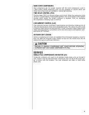
... and where start -up through an authorized distributor. ! With the complete model number for their unit. Caution must be used on some three phase units. 19 Two pole contactors are used on all standard single phase units up . Low ambient control should be exercised when servicing as only one leg of the power supply is in order to reduce light dimming. OUTDOOR UNIT COVERS Outdoor condensing unit covers are...
... and where start -up through an authorized distributor. ! With the complete model number for their unit. Caution must be used on some three phase units. 19 Two pole contactors are used on all standard single phase units up . Low ambient control should be exercised when servicing as only one leg of the power supply is in order to reduce light dimming. OUTDOOR UNIT COVERS Outdoor condensing unit covers are...
Installation Instructions
Page 20
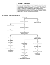
... the shortcuts. Start Capacitor Potential Relay Compressor Internal Overload Open Compressor Winding Open Unit Wiring and Connections NO Circuit Breakers or Fuses Open YES Compressor Winding Grounded Condenser Fan Grounded Grounded Capacitor Replace Fuses or Reset Breakers and Recheck YES Go to Mechanical Checks NO Voltage on Line Side of thought that the chart will learn where to a likely conclusion. TROUBLE SHOOTING In diagnosing common faults in the air conditioning system, it is useful to present...
... the shortcuts. Start Capacitor Potential Relay Compressor Internal Overload Open Compressor Winding Open Unit Wiring and Connections NO Circuit Breakers or Fuses Open YES Compressor Winding Grounded Condenser Fan Grounded Grounded Capacitor Replace Fuses or Reset Breakers and Recheck YES Go to Mechanical Checks NO Voltage on Line Side of thought that the chart will learn where to a likely conclusion. TROUBLE SHOOTING In diagnosing common faults in the air conditioning system, it is useful to present...

Installation Instructions
Page 22
...line service valve. 2. Convert the liquid line pressure to saturated temperature. TTAABBLLEE192 TTEEMMPPEERRAATTUURREEPPRREESSSSUURE CHART TEMP (...temperature. 5. TAABBLLEE 1130 AIR CONDITIONING SYSTEM TTRROOUUBBLLEESSHHOOOOTTIINNGGTTIIPPSS AIR CONDITIONING SYSTEM TROUBLESHOOTING TIPS SYSTEM PROBLEM INDICATORS DISCHARGE PRESSURE SUCTION PRESSURE SUPERHEAT SUBCOOLING COMPRESSOR AMPS Overcharge High High Low High High Undercharge Low Low High Low Low Liquid Restriction (Drier) Low Low High High Low Low Evaporator Airflow Low Low Low Low Low Dirty Condenser...
...line service valve. 2. Convert the liquid line pressure to saturated temperature. TTAABBLLEE192 TTEEMMPPEERRAATTUURREEPPRREESSSSUURE CHART TEMP (...temperature. 5. TAABBLLEE 1130 AIR CONDITIONING SYSTEM TTRROOUUBBLLEESSHHOOOOTTIINNGGTTIIPPSS AIR CONDITIONING SYSTEM TROUBLESHOOTING TIPS SYSTEM PROBLEM INDICATORS DISCHARGE PRESSURE SUCTION PRESSURE SUPERHEAT SUBCOOLING COMPRESSOR AMPS Overcharge High High Low High High Undercharge Low Low High Low Low Liquid Restriction (Drier) Low Low High High Low Low Evaporator Airflow Low Low Low Low Low Dirty Condenser...
Installation Instructions
Page 23
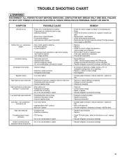
... restriction - check for 24 volts at contactor coil - Cooling mode Low head-high vapor pressures Low vapor - replace air filter • Remove or replace defective component • Change to correct size piston • Change coil assembly • Clean coil • Correct system charge • Repair or replace • Recover refrigerant, evacuate & recharge • Change to unit service panel • Recover refrigerant, evacuate & recharge, add filter drier • At compressor terminals, voltage must be approximately 400 CFM...
... restriction - check for 24 volts at contactor coil - Cooling mode Low head-high vapor pressures Low vapor - replace air filter • Remove or replace defective component • Change to correct size piston • Change coil assembly • Clean coil • Correct system charge • Repair or replace • Recover refrigerant, evacuate & recharge • Change to unit service panel • Recover refrigerant, evacuate & recharge, add filter drier • At compressor terminals, voltage must be approximately 400 CFM...


