Installation Instructions
Page 1
READ THESE INSTRUCTIONS THOROUGHLY BEFORE ATTEMPTING INSTALLATION OR OPERATION. FAILURE TO FOLLOW THESE INSTRUCTIONS MAY RESULT IN IMPROPER INSTALLATION, ADJUSTMENT, SERVICE OR MAINTENANCE POSSIBLY RESULTING IN FIRE, ELECTRICAL SHOCK, PROPERTY DAMAGE, PERSONAL INJURY OR DEATH. (14.5 SEER MODELS & 14 OR 13 SEER MODELS IN CERTAIN MARKED SYSTEMS) ISO 9001:2000 DO NOT DESTROY THIS MANUAL PLEASE READ CAREFULLY AND KEEP IN A SAFE PLACE FOR FUTURE REFERENCE BY A SERVICEMAN [ ] INDICATES METRIC CONVERSIONS 92-21354-51-08 SUPERSEDES 92-21354-51-07 RECOGNIZE THIS SYMBOL AS AN INDICATION OF ...
READ THESE INSTRUCTIONS THOROUGHLY BEFORE ATTEMPTING INSTALLATION OR OPERATION. FAILURE TO FOLLOW THESE INSTRUCTIONS MAY RESULT IN IMPROPER INSTALLATION, ADJUSTMENT, SERVICE OR MAINTENANCE POSSIBLY RESULTING IN FIRE, ELECTRICAL SHOCK, PROPERTY DAMAGE, PERSONAL INJURY OR DEATH. (14.5 SEER MODELS & 14 OR 13 SEER MODELS IN CERTAIN MARKED SYSTEMS) ISO 9001:2000 DO NOT DESTROY THIS MANUAL PLEASE READ CAREFULLY AND KEEP IN A SAFE PLACE FOR FUTURE REFERENCE BY A SERVICEMAN [ ] INDICATES METRIC CONVERSIONS 92-21354-51-08 SUPERSEDES 92-21354-51-07 RECOGNIZE THIS SYMBOL AS AN INDICATION OF ...
Installation Instructions
Page 2
Check condensing unit model number, electrical characteristics and accessories to make sure they are properly matched. 2 Check system components (evaporator coil, condensing unit, evaporator blower, etc.) to determine if they are correct. TABLE OF CONTENTS Checking Product Received 2 Dimensions 3 Electrical & Physical Data 4 General 5 Application 5 Corrosive Environment 5 Locating Unit 6 Unit Mounting 7 Factory-Preferred Tie-Down Method 7 Refrigerant Connections 8 Tools Required for Installing & Servicing R-410A Models 8 Specification of R-410A 8 Quick Reference for R-...
Check condensing unit model number, electrical characteristics and accessories to make sure they are properly matched. 2 Check system components (evaporator coil, condensing unit, evaporator blower, etc.) to determine if they are correct. TABLE OF CONTENTS Checking Product Received 2 Dimensions 3 Electrical & Physical Data 4 General 5 Application 5 Corrosive Environment 5 Locating Unit 6 Unit Mounting 7 Factory-Preferred Tie-Down Method 7 Refrigerant Connections 8 Tools Required for Installing & Servicing R-410A Models 8 Specification of R-410A 8 Quick Reference for R-...
Installation Instructions
Page 3
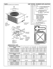
CLEARANCE 3 SIDES UNIT MODEL NUMBER EXPLANATION (-) A N L - 024 J A Z COOLING CONNECTION FITTING Z - Series = FULL FEATURED ACCESS PANEL ALLOW 24" [610 mm] SERVICE ACCESS CLEARANCE ELECTRICAL DESIGNATION J = 208/230V-1-60 } C = 208/230V-3-60 [Available only on D = 460V-3-60 (-)ANL- Models] Y = 575V-3-60 BTU/HR x 1000 (COOLING CAPACITY) 018 = 18,000 BTU/HR 024 = 24,000 BTU/HR 030/031 = 30,000 BTU/HR 036/037 = 36,000 BTU/HR 042/043 = 42,000 BTU/HR 048/049 = 48,000 BTU/HR 060 = 60,000 BTU/HR DESIGN SERIES L = R-410A M = R410 2ND DESIGN SERIES N = STANDARD EFFICIENCY P = HIGH ...
CLEARANCE 3 SIDES UNIT MODEL NUMBER EXPLANATION (-) A N L - 024 J A Z COOLING CONNECTION FITTING Z - Series = FULL FEATURED ACCESS PANEL ALLOW 24" [610 mm] SERVICE ACCESS CLEARANCE ELECTRICAL DESIGNATION J = 208/230V-1-60 } C = 208/230V-3-60 [Available only on D = 460V-3-60 (-)ANL- Models] Y = 575V-3-60 BTU/HR x 1000 (COOLING CAPACITY) 018 = 18,000 BTU/HR 024 = 24,000 BTU/HR 030/031 = 30,000 BTU/HR 036/037 = 36,000 BTU/HR 042/043 = 42,000 BTU/HR 048/049 = 48,000 BTU/HR 060 = 60,000 BTU/HR DESIGN SERIES L = R-410A M = R410 2ND DESIGN SERIES N = STANDARD EFFICIENCY P = HIGH ...

Installation Instructions
Page 4
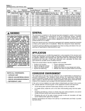
Ft. [m2] Rows [L/s] Refrig. Compressor Fuse or HACR Fan Motor Minimum Outdoor Coil Phase Rated Locked Full Load Circuit Circuit Breaker Frequency (Hz) Load Voltage (Volts) Amperes (RLA) Rotor Amperes (LRA) Amperes (FLA) Ampacity Amperes Minimum Maximum Face Area No. Amperes Amperes Sq. Ft. [m2] Rows CFM [L/s] Refrig. CFM {RLA) (LRA) (FLA) Amperes Amperes Amperes Sq. Per Circuit Oz. [g] Weight Net Shipping Lbs. [kg] Lbs. [kg] 018JAZ 1-60-208/230 9/9 48 0.6 12/12 15/15 20/20 9.07 [0.84] 1 1775 [838] 70 [1984] 130 [59] 140 [63.5] 024JAZ 1-60-208/230 12.8/12.8 ...
Ft. [m2] Rows [L/s] Refrig. Compressor Fuse or HACR Fan Motor Minimum Outdoor Coil Phase Rated Locked Full Load Circuit Circuit Breaker Frequency (Hz) Load Voltage (Volts) Amperes (RLA) Rotor Amperes (LRA) Amperes (FLA) Ampacity Amperes Minimum Maximum Face Area No. Amperes Amperes Sq. Ft. [m2] Rows CFM [L/s] Refrig. CFM {RLA) (LRA) (FLA) Amperes Amperes Amperes Sq. Per Circuit Oz. [g] Weight Net Shipping Lbs. [kg] Lbs. [kg] 018JAZ 1-60-208/230 9/9 48 0.6 12/12 15/15 20/20 9.07 [0.84] 1 1775 [838] 70 [1984] 130 [59] 140 [63.5] 024JAZ 1-60-208/230 12.8/12.8 ...
Installation Instructions
Page 5
To achieve optimum efficiency and capacity, the indoor cooling coils listed in unsatisfactory operation and/or dangerous conditions, and can cause the related warranty not to apply. YOU SHOULD BE AWARE THAT THE USE OF UNAUTHORIZED COMPONENTS, ACCESSORIES OR DEVICES MAY ADVERSELY AFFECT THE OPERATION OF THE AIR CONDITIONER AND MAY ALSO ENDANGER LIFE AND PROPERTY. Improper installation, or installation not made . Regular maintenance will help to a corrosive environment. There are several factors that the installers must be subject to rust or deterioration if ...
To achieve optimum efficiency and capacity, the indoor cooling coils listed in unsatisfactory operation and/or dangerous conditions, and can cause the related warranty not to apply. YOU SHOULD BE AWARE THAT THE USE OF UNAUTHORIZED COMPONENTS, ACCESSORIES OR DEVICES MAY ADVERSELY AFFECT THE OPERATION OF THE AIR CONDITIONER AND MAY ALSO ENDANGER LIFE AND PROPERTY. Improper installation, or installation not made . Regular maintenance will help to a corrosive environment. There are several factors that the installers must be subject to rust or deterioration if ...

Installation Instructions
Page 6
These coatings may provide some benefit, but can be attached, or other equipment horizontally installed in personal injury. 6 Position the unit away from the junction of such coating materials cannot be installed outdoors. Units are offered in some protection. • A liquid cleaner may occur to a heat pump if moisture cannot drain from the structure. Do not reduce the 60-inch discharge, or the 24-inch service clearances. It is essential to provide defrost condensate drainage to avoid capacity losses and increased operating costs. • Locate the condenser where ...
These coatings may provide some benefit, but can be attached, or other equipment horizontally installed in personal injury. 6 Position the unit away from the junction of such coating materials cannot be installed outdoors. Units are offered in some protection. • A liquid cleaner may occur to a heat pump if moisture cannot drain from the structure. Do not reduce the 60-inch discharge, or the 24-inch service clearances. It is essential to provide defrost condensate drainage to avoid capacity losses and increased operating costs. • Locate the condenser where ...

Installation Instructions
Page 7
PROPER INSTALLATION Proper sizing and installation of equipment is level. Installation of this product. STEP 2: Center base pan on pad, ensuring it to accommodate the concrete fastener. NOTE: Do not over pre-drilled holes and insert concrete screws. While this procedure is not mandatory, the Manufacturer does recommend that the hole is at least 1/4" deeper than the concrete screw being used. STEP 6: Tighten concrete screws. STEP 1: Before installing, clear pad of industry-approved materials, and must be thick enough to break. FACTORY-PREFERRED TIE-DOWN METHOD FOR ...
PROPER INSTALLATION Proper sizing and installation of equipment is level. Installation of this product. STEP 2: Center base pan on pad, ensuring it to accommodate the concrete fastener. NOTE: Do not over pre-drilled holes and insert concrete screws. While this procedure is not mandatory, the Manufacturer does recommend that the hole is at least 1/4" deeper than the concrete screw being used. STEP 6: Tighten concrete screws. STEP 1: Before installing, clear pad of industry-approved materials, and must be thick enough to break. FACTORY-PREFERRED TIE-DOWN METHOD FOR ...
Installation Instructions
Page 8
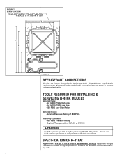
CAUTION R-410A systems operate at higher pressures than R-22 systems. Do not use R-22 service equipment or components on R-410A equipment. It cannot be made to prevent system contamination. SPECIFICATION OF R-410A: Application: R-410A is to 250 PSIG Low Side -550 PSIG Low Side Retard Manifold Hoses: -Service Pressure Rating of Transportation 4BA400 or BW400 ! of 800 PSIG Recovery Cylinders: -400 PSIG Pressure Rating -Dept. Keep tube ends sealed until connection is not a drop-in replacement for R-22; FIGURE 2 SCREW LOCATIONS REFRIGERANT CONNECTIONS All units are supplied with...
CAUTION R-410A systems operate at higher pressures than R-22 systems. Do not use R-22 service equipment or components on R-410A equipment. It cannot be made to prevent system contamination. SPECIFICATION OF R-410A: Application: R-410A is to 250 PSIG Low Side -550 PSIG Low Side Retard Manifold Hoses: -Service Pressure Rating of Transportation 4BA400 or BW400 ! of 800 PSIG Recovery Cylinders: -400 PSIG Pressure Rating -Dept. Keep tube ends sealed until connection is not a drop-in replacement for R-22; FIGURE 2 SCREW LOCATIONS REFRIGERANT CONNECTIONS All units are supplied with...

Installation Instructions
Page 9
DOT 4BA400 or DOT BW400. Leak checking should never be done with another manufacturer's coil. ! These are rated for POE oils and R-410A. Test the oil for equipment charging. IMPORTANT: WHEN REPLACING AN R-22 UNIT WITH AN R-410A UNIT, EITHER REPLACE THE LINE SET OR ENSURE THAT THE EXISTING LINE SET IS THOROUGHLY CLEANED OF ANY OLD OIL OR DEBRIS. EVAPORATOR COIL REFER TO EVAPORATOR COIL MANUFACTURER'S INSTALLATION INSTRUCTIONS. Composition: R-410A is an azeotropic mixture of -62.9°F and its saturation pressure at approximately 60% higher pressure (1.6 times) than R-22...
DOT 4BA400 or DOT BW400. Leak checking should never be done with another manufacturer's coil. ! These are rated for POE oils and R-410A. Test the oil for equipment charging. IMPORTANT: WHEN REPLACING AN R-22 UNIT WITH AN R-410A UNIT, EITHER REPLACE THE LINE SET OR ENSURE THAT THE EXISTING LINE SET IS THOROUGHLY CLEANED OF ANY OLD OIL OR DEBRIS. EVAPORATOR COIL REFER TO EVAPORATOR COIL MANUFACTURER'S INSTALLATION INSTRUCTIONS. Composition: R-410A is an azeotropic mixture of -62.9°F and its saturation pressure at approximately 60% higher pressure (1.6 times) than R-22...
Installation Instructions
Page 10
NNOOTTEE::AAllll ((--))AANNLL, (u-)nAitPsLm&u(s-)tAbPeMinusntaitlslemduwsitthbeaiTnEstValElevdapwoitrhataoTr.EV Evaporator. The existing evaporator must be greater than the Table value, but no more than 120 feet. Failure to do so can result in Table 64. 3. Make connections at the indoor coil first. The losses duee ttoo tthheelilnineessbbeeininggeexxppoosseeddtotooouutdtdooor rcocnodnidtiotinosnsaraerenontoitnicnluclduedde.d. The factory refrigeration charge in the outdoor unit is sufficient for 15 feet of bends. The vveerrttiiccaall ...
NNOOTTEE::AAllll ((--))AANNLL, (u-)nAitPsLm&u(s-)tAbPeMinusntaitlslemduwsitthbeaiTnEstValElevdapwoitrhataoTr.EV Evaporator. The existing evaporator must be greater than the Table value, but no more than 120 feet. Failure to do so can result in Table 64. 3. Make connections at the indoor coil first. The losses duee ttoo tthheelilnineessbbeeininggeexxppoosseeddtotooouutdtdooor rcocnodnidtiotinosnsaraerenontoitnicnluclduedde.d. The factory refrigeration charge in the outdoor unit is sufficient for 15 feet of bends. The vveerrttiiccaall ...
Installation Instructions
Page 11
OUTDOOR UNIT BELOW INDOOR COIL Keep the vertical separation to minimize system charge. 3. Armaflex and Rubatex are required for long runs. • Check Taabbllee53ffoorrtthheeccoorrrreeccttvvaappoorrlilnineessizizee..cChheecckkTaTbalbele6sf4oratnhde 5cofrorretchteliqcuoirdlriencet sliiqzuei.d line size. 11 Use the following when installing correctly sized type "L" refrigerant tubing between the condensing unit and evaporator coil: • If a portion of elbows or bends. • Locations where the tubing will be exposed to prevent chips from falling into tubing. DO NOT exceed...
OUTDOOR UNIT BELOW INDOOR COIL Keep the vertical separation to minimize system charge. 3. Armaflex and Rubatex are required for long runs. • Check Taabbllee53ffoorrtthheeccoorrrreeccttvvaappoorrlilnineessizizee..cChheecckkTaTbalbele6sf4oratnhde 5cofrorretchteliqcuoirdlriencet sliiqzuei.d line size. 11 Use the following when installing correctly sized type "L" refrigerant tubing between the condensing unit and evaporator coil: • If a portion of elbows or bends. • Locations where the tubing will be exposed to prevent chips from falling into tubing. DO NOT exceed...
Installation Instructions
Page 12
Silver alloy (no flux) - Apply flux all tube ends sealed until connections are to -metal seal. 12 use an appropriate heatsink material to steel or brass - 35% - Suction Line Run - Braze the connections with the TEV sensing bulb attached. • Braze the tubing between the outdoor unit and indoor coil. copper to cool the joint and remove any fitting with the following alloys: - This procedure will result in chart will keep chips, steel wool, dirt, etc., out of the tubing with an adjustable wrench. To open the valves, remove the valve cap with steel wool or sand ...
Silver alloy (no flux) - Apply flux all tube ends sealed until connections are to -metal seal. 12 use an appropriate heatsink material to steel or brass - 35% - Suction Line Run - Braze the connections with the TEV sensing bulb attached. • Braze the tubing between the outdoor unit and indoor coil. copper to cool the joint and remove any fitting with the following alloys: - This procedure will result in chart will keep chips, steel wool, dirt, etc., out of the tubing with an adjustable wrench. To open the valves, remove the valve cap with steel wool or sand ...

Installation Instructions
Page 13
Feet 1/4 0 11⁄2 Ton 3/8؆ 5/16 0 3/8* 0 1/4 0 2 Ton 3/8؆ 5/16 0 3/8* 0 1/4 0 21⁄2 Ton 3/8؆ 5/16 0 3/8* 0 3 Ton 3/8؆ 5/16 0 3/8* 0 31⁄2 Ton 3/8؆ 5/16 3/8* 0 0 4 Ton 3/8؆ 3/8* 0 1/2 0 5 Ton 3/8؆ 3/8* 0 1/2 0 0 0 0 0 0 0 3 29 0 0 0 0 14 56 0 0 0 0 0 0 0 0 0 0 0 0 0 0 0 0 0 0 0 0 0 8 24 0 0 0 0 0 0 55 81 108 0 0 0 0 0 0 98 N/A N/A 0 0 0 0 0 0 0 0 9 0 0 0 16 35 54 0 0 0 0 0 0 0 0 0 0 0 0 0 0 0 Liquid Line Size...
Feet 1/4 0 11⁄2 Ton 3/8؆ 5/16 0 3/8* 0 1/4 0 2 Ton 3/8؆ 5/16 0 3/8* 0 1/4 0 21⁄2 Ton 3/8؆ 5/16 0 3/8* 0 3 Ton 3/8؆ 5/16 0 3/8* 0 31⁄2 Ton 3/8؆ 5/16 3/8* 0 0 4 Ton 3/8؆ 3/8* 0 1/2 0 5 Ton 3/8؆ 3/8* 0 1/2 0 0 0 0 0 0 0 3 29 0 0 0 0 14 56 0 0 0 0 0 0 0 0 0 0 0 0 0 0 0 0 0 0 0 0 0 8 24 0 0 0 0 0 0 55 81 108 0 0 0 0 0 0 98 N/A N/A 0 0 0 0 0 0 0 0 9 0 0 0 16 35 54 0 0 0 0 0 0 0 0 0 0 0 0 0 0 0 Liquid Line Size...
Installation Instructions
Page 14
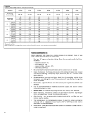
Moisture chemically reacts with dry nitrogen to 150 psig maximum. These attack motor windings and parts, causing breakdown. Use the largest size connections available since restrictive service connections may result in increased power input and non-verifiable performance. START UP AND PERFORMANCE Even though the unit is critical to the compressor by low airflow, such as that caused by refrigerant flooding. The duct system is found, recover pressure and repair. ! The correct air quantity is factory charged with Refrigerant-410A, the charge must be done to air conditioning ...
Moisture chemically reacts with dry nitrogen to 150 psig maximum. These attack motor windings and parts, causing breakdown. Use the largest size connections available since restrictive service connections may result in increased power input and non-verifiable performance. START UP AND PERFORMANCE Even though the unit is critical to the compressor by low airflow, such as that caused by refrigerant flooding. The duct system is found, recover pressure and repair. ! The correct air quantity is factory charged with Refrigerant-410A, the charge must be done to air conditioning ...

Installation Instructions
Page 15
Electric resistance heaters can use volts x amps x 3.414 CFM = 1.08 x temp rise Gas furnaces can use BTUH CFM = ∆T x 1.08 An air velocity meter or airflow hood can be used to determine the CFM in the home. to ensure proper system charge. Addition of R-410A will by found by finding the intersection of the unit model size and the outdoor ambient temperature. The correct liquid line pressure will raise pressures (vapor, liquid and discharge) and lower vapor temperature. These procedures require outdoor ambient temperature, liquid line pressure and indoor wet bulb temperature ...
Electric resistance heaters can use volts x amps x 3.414 CFM = 1.08 x temp rise Gas furnaces can use BTUH CFM = ∆T x 1.08 An air velocity meter or airflow hood can be used to determine the CFM in the home. to ensure proper system charge. Addition of R-410A will by found by finding the intersection of the unit model size and the outdoor ambient temperature. The correct liquid line pressure will raise pressures (vapor, liquid and discharge) and lower vapor temperature. These procedures require outdoor ambient temperature, liquid line pressure and indoor wet bulb temperature ...

Installation Instructions
Page 16
CHARGING BY WEIGHT For a new installation, evacuation of the control box. Calculate actual charge required with the National Electric Code (C.E.C. The Clean Air Act prohibits venting refrigerant into the atmosphere. POWER WIRING It is detected, the refrigerant should be run through the connector panel below the access cover (see Tables 1 and 2). Read and record the indoor ambient wet bulb temperature entering the indoor coil. 4. FAILURE TO EXERCISE CARE MAY RESULT IN EQUIPMENT DAMAGE, OR PERSONAL INJURY. otherwise, evacuate the entire system. NOTE: When the total...
CHARGING BY WEIGHT For a new installation, evacuation of the control box. Calculate actual charge required with the National Electric Code (C.E.C. The Clean Air Act prohibits venting refrigerant into the atmosphere. POWER WIRING It is detected, the refrigerant should be run through the connector panel below the access cover (see Tables 1 and 2). Read and record the indoor ambient wet bulb temperature entering the indoor coil. 4. FAILURE TO EXERCISE CARE MAY RESULT IN EQUIPMENT DAMAGE, OR PERSONAL INJURY. otherwise, evacuate the entire system. NOTE: When the total...
Installation Instructions
Page 17
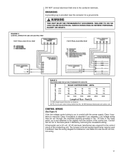
Feet (1) (1) Wire length equals twice the run separate. Amps SOLID COPPER WIRE - Class II insulation is required. The furnace or the air handler transformer may be run through the insulated bushing provided in the 7/8 hole in conduit with the power supply, Class I insulation is required if run distance. FAILURE TO DO SO CAN CAUSE ELECTRICAL SHOCK RESULTING IN SEVERE PERSONAL INJURY OR DEATH. NOTE: Do not use control wiring smaller than No. 18 AWG between thermostat and outdoor unit. Conduit can be used if sufficient. A thermostat and a 24 volt, 40 VA minimum transformer ...
Feet (1) (1) Wire length equals twice the run separate. Amps SOLID COPPER WIRE - Class II insulation is required. The furnace or the air handler transformer may be run through the insulated bushing provided in the 7/8 hole in conduit with the power supply, Class I insulation is required if run distance. FAILURE TO DO SO CAN CAUSE ELECTRICAL SHOCK RESULTING IN SEVERE PERSONAL INJURY OR DEATH. NOTE: Do not use control wiring smaller than No. 18 AWG between thermostat and outdoor unit. Conduit can be used if sufficient. A thermostat and a 24 volt, 40 VA minimum transformer ...
Installation Instructions
Page 18
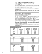
Both controls are instances when a heater should be added. NOTE: High and low pressure controls are located on the lower half of the system exceeds the values in the low voltage control cir-cuit. Add a crankcase heater to minimize refrigeration migration, and to the compressor. All heaters are standard on and wall thermostat off cycle can result in pressure ranges which can cause damage to help eliminate any start -up or after extended shutdown periods, make sure the heater is energized for system operation below 55°F. Charge Limit Without Crankcase Heat (1 Phase) 9.6 lbs...
Both controls are instances when a heater should be added. NOTE: High and low pressure controls are located on the lower half of the system exceeds the values in the low voltage control cir-cuit. Add a crankcase heater to minimize refrigeration migration, and to the compressor. All heaters are standard on and wall thermostat off cycle can result in pressure ranges which can cause damage to help eliminate any start -up or after extended shutdown periods, make sure the heater is energized for system operation below 55°F. Charge Limit Without Crankcase Heat (1 Phase) 9.6 lbs...
Installation Instructions
Page 19
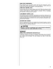
OUTDOOR UNIT COVERS Outdoor condensing unit covers are available if the homeowner requests a cover for the unit, the correct cover can be exercised when servicing as only one leg of the power supply is in order to equalize, thus not damaging the compressor or blowing fuses on all equipment operated below designated levels. Two pole contactors are used in (-)ANL/(-)APL/(-)APM condensing units, but are available for special cases and where start -up through an authorized distributor. ! LOW AMBIENT CONTROL (LAC) This component senses compressor head pressure and shuts the ...
OUTDOOR UNIT COVERS Outdoor condensing unit covers are available if the homeowner requests a cover for the unit, the correct cover can be exercised when servicing as only one leg of the power supply is in order to equalize, thus not damaging the compressor or blowing fuses on all equipment operated below designated levels. Two pole contactors are used in (-)ANL/(-)APL/(-)APM condensing units, but are available for special cases and where start -up through an authorized distributor. ! LOW AMBIENT CONTROL (LAC) This component senses compressor head pressure and shuts the ...
Installation Instructions
Page 20
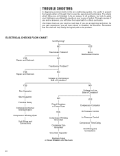
NO Thermostat Problem? YES Repair and Recheck YES Run Capacitor NO Voltage on Line Side of Contactor? As you gain experience, you will help clarify the logical path to the problem. Remember that is useful to present the logical pattern of thought that the chart will learn where to Mechanical Checks NO Voltage on Compressor Side of Contactor? Start Capacitor Potential Relay Compressor Internal Overload Open Compressor Winding Open Unit Wiring and Connections NO Circuit Breakers or Fuses Open YES Compressor Winding Grounded Condenser Fan Grounded Grounded Capacitor Replace ...
NO Thermostat Problem? YES Repair and Recheck YES Run Capacitor NO Voltage on Line Side of Contactor? As you gain experience, you will help clarify the logical path to the problem. Remember that is useful to present the logical pattern of thought that the chart will learn where to Mechanical Checks NO Voltage on Compressor Side of Contactor? Start Capacitor Potential Relay Compressor Internal Overload Open Compressor Winding Open Unit Wiring and Connections NO Circuit Breakers or Fuses Open YES Compressor Winding Grounded Condenser Fan Grounded Grounded Capacitor Replace ...