
English Manual
Page 3
... move the walking belt while the power is capable of high speeds. Wear appropriate exercise clothes while using the treadmill. 17. structions in damage to ensure that blocks air openings. To protect the floor or carpet from damage, place a mat under age 12 and pets away from the treadmill at all times. 7. When connecting the power cord (see HOW TO TURN ON THE POWER on...
... move the walking belt while the power is capable of high speeds. Wear appropriate exercise clothes while using the treadmill. 17. structions in damage to ensure that blocks air openings. To protect the floor or carpet from damage, place a mat under age 12 and pets away from the treadmill at all times. 7. When connecting the power cord (see HOW TO TURN ON THE POWER on...
English Manual
Page 4
... any object into any opening on page 5 for in a commercial, rental, or institutional setting. 26. Always unplug the power cord immediately after use this treadmill in -home use only. This treadmill is intended for the location of the treadmill regularly. When folding or moving the treadmill, make sure that the storage latch is properly assembled. (See ASSEMBLY on page 6, and HOW TO FOLD AND MOVE THE TREADMILL on page 20.) You...
... any object into any opening on page 5 for in a commercial, rental, or institutional setting. 26. Always unplug the power cord immediately after use this treadmill in -home use only. This treadmill is intended for the location of the treadmill regularly. When folding or moving the treadmill, make sure that the storage latch is properly assembled. (See ASSEMBLY on page 6, and HOW TO FOLD AND MOVE THE TREADMILL on page 20.) You...
English Manual
Page 5
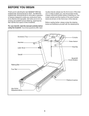
..., read - The 8000 ES treadmill with the labeled parts. Before reading further, please review the drawing below and familiarize yourself with Universal Dock for iPod®. ing this manual, please see the front cover of other treadmills. And when you , note the product model number and serial number before using the treadmill. Accessory Tray Handrail Latch Knob Upright Walking Belt Foot Rail Console Pulse Sensor Key/Clip Reset/Off Circuit Breaker Idler Roller Adjustment Bolts Platform Cushion 5
..., read - The 8000 ES treadmill with the labeled parts. Before reading further, please review the drawing below and familiarize yourself with Universal Dock for iPod®. ing this manual, please see the front cover of other treadmills. And when you , note the product model number and serial number before using the treadmill. Accessory Tray Handrail Latch Knob Upright Walking Belt Foot Rail Console Pulse Sensor Key/Clip Reset/Off Circuit Breaker Idler Roller Adjustment Bolts Platform Cushion 5

English Manual
Page 7
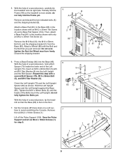
1. Partially fold the Frame (48) so that the power cord is more stable; Locate a tie in the indicated hole in the Base, and use the tie to pull the Upright Wire out of a second person, carefully tip the treadmill onto its left side. Attach a Base Pad (81) to the Base (85). Then, attach a Base Pad (81) in the location shown with an...
1. Partially fold the Frame (48) so that the power cord is more stable; Locate a tie in the indicated hole in the Base, and use the tie to pull the Upright Wire out of a second person, carefully tip the treadmill onto its left side. Attach a Base Pad (81) to the Base (85). Then, attach a Base Pad (81) in the location shown with an...
English Manual
Page 9
...Orient the Left Upright (73) and the Left Upright Spacer (83) as shown. Set the Console (87) face down on the floor. 7. Remove the six M4.2 x 19mm Screws (1). Remove and discard the two indicated bolts (A) and the shipping bracket (B). Attach a Wheel (...Press a Base Endcap (82) into the Left Upright and the Bolt Spacer. do not fully fold the Frame yet. Save the Pulse Support and all six M4.2 x 19mm Screws (1) for step 9. 6 5 8 82 79 85 73 83 7 1 1 109 1 87 9 do not fully tighten the Bolts yet. Then, attach a Base Pad (81) in the location shown with a second Bolt...
...Orient the Left Upright (73) and the Left Upright Spacer (83) as shown. Set the Console (87) face down on the floor. 7. Remove the six M4.2 x 19mm Screws (1). Remove and discard the two indicated bolts (A) and the shipping bracket (B). Attach a Wheel (...Press a Base Endcap (82) into the Left Upright and the Bolt Spacer. do not fully fold the Frame yet. Save the Pulse Support and all six M4.2 x 19mm Screws (1) for step 9. 6 5 8 82 79 85 73 83 7 1 1 109 1 87 9 do not fully tighten the Bolts yet. Then, attach a Base Pad (81) in the location shown with a second Bolt...
English Manual
Page 10
..., remove the plastic tie. Connect the Console Ground Wire (40) on the Pulse Support to the Console (87) in the location shown. Tighten two M4 x 20mm Screws (3) with two M4.2 x 19mm Screws (1). Attach the Right Handrail (90) with two M4.2 Star Washers (70) into the console assembly and set the Pulse Support on the console assembly. Note: There are no wires on the console wire into the Pulse Support (109) and the console assembly. Hold the Pulse Support...
..., remove the plastic tie. Connect the Console Ground Wire (40) on the Pulse Support to the Console (87) in the location shown. Tighten two M4 x 20mm Screws (3) with two M4.2 x 19mm Screws (1). Attach the Right Handrail (90) with two M4.2 Star Washers (70) into the console assembly and set the Pulse Support on the console assembly. Note: There are no wires on the console wire into the Pulse Support (109) and the console assembly. Hold the Pulse Support...

English Manual
Page 11
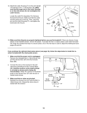
... Left Handrail (89). See steps 4 and 6. If necessary, press the Cage Nuts (38) into the Right Upright (78). Remove the wire tie from the Upright Wire and the tie from the Right Handrail (90) and the Left Handrail (not shown). Set the console assembly on the Right Upright (78) and the Left Upright (not shown). Then, fully tighten all four Bolts. Tighten the M10 x 96mm...
... Left Handrail (89). See steps 4 and 6. If necessary, press the Cage Nuts (38) into the Right Upright (78). Remove the wire tie from the Upright Wire and the tie from the Right Handrail (90) and the Left Handrail (not shown). Set the console assembly on the Right Upright (78) and the Left Upright (not shown). Then, fully tighten all four Bolts. Tighten the M10 x 96mm...
English Manual
Page 12
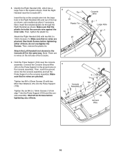
Attach the Latch Housing (71) to the indicated wire extending from the Console Base (88). Locate the Latch Pin Assembly (72). If there are on the pin. Keep the included hex keys in the Latch Housing is used to adjust the walking belt (see page 19), follow the steps below to the plastic posts on the treadmill decals, remove the plastic. Make sure that all parts are pinched. Connect the wire on...
Attach the Latch Housing (71) to the indicated wire extending from the Console Base (88). Locate the Latch Pin Assembly (72). If there are on the pin. Keep the included hex keys in the Latch Housing is used to adjust the walking belt (see page 19), follow the steps below to the plastic posts on the treadmill decals, remove the plastic. Make sure that all parts are pinched. Connect the wire on...

English Manual
Page 13
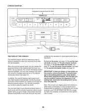
... control system of least resistance for 120 volts AC and 15 amps. OPERATION AND ADJUSTMENT THE PRE-LUBRICATED WALKING BELT Your treadmill features a walking belt coated with your treadmill (see draw- IMPORTANT: Never apply silicone spray or other appli- an equipment-grounding conductor and a grounding plug. ances being damaged, always use a surge suppressor with highperformance lubricant. Grounding Pin Grounded Outlet Grounding Plug Grounded Outlet Box Adapter...
... control system of least resistance for 120 volts AC and 15 amps. OPERATION AND ADJUSTMENT THE PRE-LUBRICATED WALKING BELT Your treadmill features a walking belt coated with your treadmill (see draw- IMPORTANT: Never apply silicone spray or other appli- an equipment-grounding conductor and a grounding plug. ances being damaged, always use a surge suppressor with highperformance lubricant. Grounding Pin Grounded Outlet Grounding Plug Grounded Outlet Box Adapter...
English Manual
Page 14
... display speed and distance in shape. As you through an effective exercise session. You can also customize your heart rate using the handgrip pulse sensor or the optional chest pulse sensor (see page 24). This product has been designed specifically to work with iPod and has been certified by the developer to the walking platform, wear clean athletic shoes while using the weight loss center. To use the manual mode...
... display speed and distance in shape. As you through an effective exercise session. You can also customize your heart rate using the handgrip pulse sensor or the optional chest pulse sensor (see page 24). This product has been designed specifically to work with iPod and has been certified by the developer to the walking platform, wear clean athletic shoes while using the weight loss center. To use the manual mode...
English Manual
Page 15
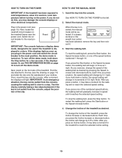
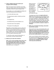
... console, adjust the position of the clip. If a classic workout or the weight loss center has been selected, remove the key and then reinsert it may take a moment for the treadmill to reach the selected incline setting. 15 To start the walking belt, press the Start button, the Speed increase button, or one of the numbered speed buttons, the walking belt will change in the power cord and switch the circuit breaker to the reset position, the demo mode...
... console, adjust the position of the clip. If a classic workout or the weight loss center has been selected, remove the key and then reinsert it may take a moment for the treadmill to reach the selected incline setting. 15 To start the walking belt, press the Start button, the Speed increase button, or one of the numbered speed buttons, the walking belt will change in the power cord and switch the circuit breaker to the reset position, the demo mode...
English Manual
Page 16
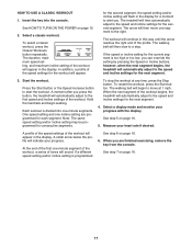
.... To reset the console, press the Stop button, remove the key, and then reinsert the key. 6. Press the Display button repeatedly to hold the pulse bar with the display. When you walk or run . • The incline level of the treadmill. Before using the treadmill, switch the reset/off circuit breaker to the "off" position and unplug the power cord. Note: If you use the handgrip pulse sensor and the optional chest pulse sensor at the lowest setting or you...
.... To reset the console, press the Stop button, remove the key, and then reinsert the key. 6. Press the Display button repeatedly to hold the pulse bar with the display. When you walk or run . • The incline level of the treadmill. Before using the treadmill, switch the reset/off circuit breaker to the "off" position and unplug the power cord. Note: If you use the handgrip pulse sensor and the optional chest pulse sensor at the lowest setting or you...
English Manual
Page 17
... workout, a series of the workout. The treadmill will then slow to the speed and incline settings for the second segment. If the speed or incline setting for the workout will automatically adjust to move one incline setting are finished exercising, remove the key from the console. A moment after you can override the setting by pressing the Speed or Incline buttons; One speed setting and one segment to start the workout. To stop . The walking belt will then move at any time, press the Stop button...
... workout, a series of the workout. The treadmill will then slow to the speed and incline settings for the second segment. If the speed or incline setting for the workout will automatically adjust to move one incline setting are finished exercising, remove the key from the console. A moment after you can override the setting by pressing the Speed or Incline buttons; One speed setting and one segment to start the workout. To stop . The walking belt will then move at any time, press the Stop button...
English Manual
Page 18
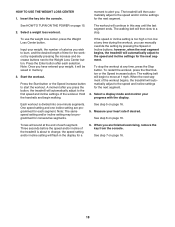
... step 6 on page 15. 2. Insert the key into one incline setting are finished exercising, remove the key from the console. moment to move at the end of the treadmill is divided into the console. See HOW TO TURN ON THE POWER on page 16. To use the weight loss center, press the Weight Loss Center button. Start the workout. The walking belt will continue in memory. 3. Note: The same speed setting and/or incline setting may...
... step 6 on page 15. 2. Insert the key into one incline setting are finished exercising, remove the key from the console. moment to move at the end of the treadmill is divided into the console. See HOW TO TURN ON THE POWER on page 16. To use the weight loss center, press the Weight Loss Center button. Start the workout. The walking belt will continue in memory. 3. Note: The same speed setting and/or incline setting may...
English Manual
Page 19
... the display demo mode. The word "English" for miles or "Metric" for iPod, you remove the key, the displays will remain lit, although the buttons will appear in the power cord, switch the reset/off the demo mode, press the Speed decrease button. To play music or audio books through the Integrated Universal Dock for iPod will be used . The display will appear in . THE OPTIONAL CHEST PULSE SENSOR An optional chest pulse sensor offers hands-free...
... the display demo mode. The word "English" for miles or "Metric" for iPod, you remove the key, the displays will remain lit, although the buttons will appear in the power cord, switch the reset/off the demo mode, press the Speed decrease button. To play music or audio books through the Integrated Universal Dock for iPod will be used . The display will appear in . THE OPTIONAL CHEST PULSE SENSOR An optional chest pulse sensor offers hands-free...
English Manual
Page 22
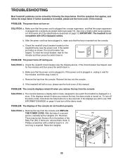
... Uprights (73, 78) down the Stop button for five minutes, and then plug it , wait for a few seconds. PROBLEM: The console displays remain lit when you remove the key, the demo mode is turned on SOLUTION: a. To turn off circuit breaker (see THE INFORMATION MODE on page 19 and turn on . To reset the circuit breaker, wait for five minutes and then press the switch back in . c Tripped Reset PROBLEM: The power turns...
... Uprights (73, 78) down the Stop button for five minutes, and then plug it , wait for a few seconds. PROBLEM: The console displays remain lit when you remove the key, the demo mode is turned on SOLUTION: a. To turn off circuit breaker (see THE INFORMATION MODE on page 19 and turn on . To reset the circuit breaker, wait for five minutes and then press the switch back in . c Tripped Reset PROBLEM: The power turns...
English Manual
Page 23
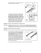
... Reed Switch. Run the treadmill for a few minutes to the minimum level. Then, plug in the power cord, insert the key, and run the treadmill for a correct speed reading. 1/8 in. 1 54 Top View 42 44 PROBLEM: The incline of this manual. 23 Idler Roller Bolts c. The treadmill will recalibrate the incline system. Using the hex key, turn both idler roller bolts counterclockwise, 1/4 of the Incline buttons. PROBLEM: The walking belt slows when walked on , see the front cover...
... Reed Switch. Run the treadmill for a few minutes to the minimum level. Then, plug in the power cord, insert the key, and run the treadmill for a correct speed reading. 1/8 in. 1 54 Top View 42 44 PROBLEM: The incline of this manual. 23 Idler Roller Bolts c. The treadmill will recalibrate the incline system. Using the hex key, turn both idler roller bolts counterclockwise, 1/4 of the Incline buttons. PROBLEM: The walking belt slows when walked on , see the front cover...
English Manual
Page 25
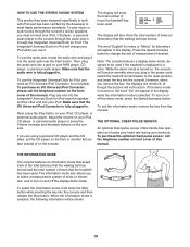
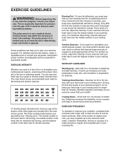
... health problems. The pulse sensor is to burn fat or to the nearest ten years). During the first few weeks of the chart (ages are essential for aerobic exercise. EXERCISE GUIDELINES WARNING: Before beginning this or any exercise program, consult your physician. For detailed exercise information, obtain a reputable book or consult your physician. Training Zone Exercise-Exercise for 20 to 10 minutes of your body uses...
... health problems. The pulse sensor is to burn fat or to the nearest ten years). During the first few weeks of the chart (ages are essential for aerobic exercise. EXERCISE GUIDELINES WARNING: Before beginning this or any exercise program, consult your physician. For detailed exercise information, obtain a reputable book or consult your physician. Training Zone Exercise-Exercise for 20 to 10 minutes of your body uses...
English Manual
Page 26
... Right Foot Hood Reed Switch Reed Switch Clip Frame Spacer Frame/Roller Ground Wire Incline Motor Idler Roller Bracket Motor Motor Bracket Lift Frame Cable Tie Lift Frame M8 Flange Nut Power Cord Controller Power Cord Grommet Reset/Off Circuit Breaker Belly Pan M4.2 Star Washer Latch Housing Latch Pin Assembly Left Upright Left Bottom Pulse Plate Audio Wire #10 x 1" Tek Screw Upright Wire Right Upright Bolt Spacer Right Upright Spacer Base Pad Base Endcap Left Upright Spacer Caution Decal Base Wheel Console Console Base Left...
... Right Foot Hood Reed Switch Reed Switch Clip Frame Spacer Frame/Roller Ground Wire Incline Motor Idler Roller Bracket Motor Motor Bracket Lift Frame Cable Tie Lift Frame M8 Flange Nut Power Cord Controller Power Cord Grommet Reset/Off Circuit Breaker Belly Pan M4.2 Star Washer Latch Housing Latch Pin Assembly Left Upright Left Bottom Pulse Plate Audio Wire #10 x 1" Tek Screw Upright Wire Right Upright Bolt Spacer Right Upright Spacer Base Pad Base Endcap Left Upright Spacer Caution Decal Base Wheel Console Console Base Left...
English Manual
Page 32
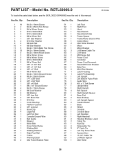
... with the use , or costs of removal or installation; Some provinces do not allow limitations on how long an implied warranty lasts. ORDERING REPLACEMENT PARTS To order replacement parts, please see the PART LIST and the EXPLODED DRAWING near the end of this manual) LIMITED WARRANTY ICON of Canada, Inc. (ICON) warrants this product to be free from the date of purchase. products used as store display models. This warranty gives...
... with the use , or costs of removal or installation; Some provinces do not allow limitations on how long an implied warranty lasts. ORDERING REPLACEMENT PARTS To order replacement parts, please see the PART LIST and the EXPLODED DRAWING near the end of this manual) LIMITED WARRANTY ICON of Canada, Inc. (ICON) warrants this product to be free from the date of purchase. products used as store display models. This warranty gives...


