

User Manual
Page 1
Keep this equipment. If you have questions, or if parts are damaged or missing, PLEASE CONTACT OUR CUSTOMER SERVICE DEPARTMENT DIRECTLY. www.proform.com CALL TOLL-FREE: 1-888-936-4266 Mon.-Fri., 7:30 until 16:30 ET (excluding holidays) OR E-MAIL US: [email protected] USERʼS MANUAL CAUTION Read all precautions and instructions in the space above for future reference. Model No. Serial Number Decal QUESTIONS? Write the serial number in this manual before using this manual for reference. PFCCEL53909.0 Serial No.
Keep this equipment. If you have questions, or if parts are damaged or missing, PLEASE CONTACT OUR CUSTOMER SERVICE DEPARTMENT DIRECTLY. www.proform.com CALL TOLL-FREE: 1-888-936-4266 Mon.-Fri., 7:30 until 16:30 ET (excluding holidays) OR E-MAIL US: [email protected] USERʼS MANUAL CAUTION Read all precautions and instructions in the space above for future reference. Model No. Serial Number Decal QUESTIONS? Write the serial number in this manual before using this manual for reference. PFCCEL53909.0 Serial No.

User Manual
Page 2
... the front cover of this manual and request a free replacement decal. Apply the decal in the location shown. If a decal is a registered trademark of the warning decal(s). TABLE OF CONTENTS WARNING DECAL PLACEMENT 2 IMPORTANT PRECAUTIONS 3 BEFORE YOU BEGIN 4 ASSEMBLY 5 HOW TO USE THE ELLIPTICAL 15 MAINTENANCE AND TROUBLESHOOTING 21 EXERCISE GUIDELINES 23 PART LIST 25 EXPLODED DRAWING 26 ORDERING REPLACEMENT PARTS Back Cover LIMITED WARRANTY Back Cover WARNING DECAL...
... the front cover of this manual and request a free replacement decal. Apply the decal in the location shown. If a decal is a registered trademark of the warning decal(s). TABLE OF CONTENTS WARNING DECAL PLACEMENT 2 IMPORTANT PRECAUTIONS 3 BEFORE YOU BEGIN 4 ASSEMBLY 5 HOW TO USE THE ELLIPTICAL 15 MAINTENANCE AND TROUBLESHOOTING 21 EXERCISE GUIDELINES 23 PART LIST 25 EXPLODED DRAWING 26 ORDERING REPLACEMENT PARTS Back Cover LIMITED WARRANTY Back Cover WARNING DECAL...
User Manual
Page 3
... the owner to move until the flywheel stops. To protect the floor or carpet from moisture and dust. The heart rate monitor is intended for foot protection while exercising. 3. Keep your pedaling speed in a controlled way. 14. Wear appropriate clothes while exercising; Place the elliptical on a level surface, with pre-existing health problems. 2. Keep children under the elliptical. 7. Reduce your back straight while using the elliptical. 4. do...
... the owner to move until the flywheel stops. To protect the floor or carpet from moisture and dust. The heart rate monitor is intended for foot protection while exercising. 3. Keep your pedaling speed in a controlled way. 14. Wear appropriate clothes while exercising; Place the elliptical on a level surface, with pre-existing health problems. 2. Keep children under the elliptical. 7. Reduce your back straight while using the elliptical. 4. do...
User Manual
Page 4
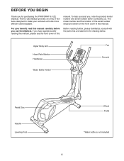
... . Upper Body Arm Heart Rate Monitor Handlebar Water Bottle Holder* Fan Console Pedal Disc Handle Leveling Foot Wheel Pedal *Water bottle is not included 4 The 6.0 ZE elliptical provides an array of features designed to make your benefit, read this manual carefully before contacting us assist you for purchasing the PROFORM® 6.0 ZE elliptical. BEFORE YOU BEGIN Thank you , note the product model number and serial number before you...
... . Upper Body Arm Heart Rate Monitor Handlebar Water Bottle Holder* Fan Console Pedal Disc Handle Leveling Foot Wheel Pedal *Water bottle is not included 4 The 6.0 ZE elliptical provides an array of features designed to make your benefit, read this manual carefully before contacting us assist you for purchasing the PROFORM® 6.0 ZE elliptical. BEFORE YOU BEGIN Thank you , note the product model number and serial number before you...
User Manual
Page 5
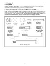
... Screw (82)-4 Shoulder Patch Bolt (31)-2 5 The number following the key number is the key number of the part, from the PART LIST near the end of the elliptical in parentheses below to the included tool(s), assembly requires a Phillips screwdriver . In addition to identify the small parts needed for assembly. The number in a cleared area and remove the packing materials. To avoid damaging parts, do not use power tools for assembly...
... Screw (82)-4 Shoulder Patch Bolt (31)-2 5 The number following the key number is the key number of the part, from the PART LIST near the end of the elliptical in parentheses below to the included tool(s), assembly requires a Phillips screwdriver . In addition to identify the small parts needed for assembly. The number in a cleared area and remove the packing materials. To avoid damaging parts, do not use power tools for assembly...
User Manual
Page 9
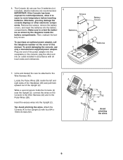
... manual. Plug one end of the power adapter into an outlet installed in accordance with four M4 x 16mm Screws (92). 7 4 42 2 28 92 39 Avoid pinching the wires 9 Remove the screws, remove the battery covers, and insert the batteries into the Upright (2). Then, reattach the battery covers. Untie and discard the wire tie attached to the Pulse Wires (28). Tip: Avoid pinching the wires. To purchase an optional power adapter, call the telephone number...
... manual. Plug one end of the power adapter into an outlet installed in accordance with four M4 x 16mm Screws (92). 7 4 42 2 28 92 39 Avoid pinching the wires 9 Remove the screws, remove the battery covers, and insert the batteries into the Upright (2). Then, reattach the battery covers. Untie and discard the wire tie attached to the Pulse Wires (28). Tip: Avoid pinching the wires. To purchase an optional power adapter, call the telephone number...

User Manual
Page 10
... are in the hexagonal holes. Do not tighten the Button Bolts yet. Attach the Console Cover (32) to the other Upper Body Leg (6) in the indicated location. Attach the Right Upper Body Arm (9) to the back of the Console (4) with two M8 x 45mm Button Bolts (76) and two M8 Jam Nuts (77). Identify the Left and Right Upper Body Arms (8, 9), which are in the same way. 9 8 76...
... are in the hexagonal holes. Do not tighten the Button Bolts yet. Attach the Console Cover (32) to the other Upper Body Leg (6) in the indicated location. Attach the Right Upper Body Arm (9) to the back of the Console (4) with two M8 x 45mm Button Bolts (76) and two M8 Jam Nuts (77). Identify the Left and Right Upper Body Arms (8, 9), which are in the same way. 9 8 76...

User Manual
Page 11
... Upright (2). 10. While a second person holds the front end of the included grease to a Shoulder 11 Patch Bolt (31). Attach each Upper Body Arm (8, 9) with an M8 x 20mm Patch Screw (80) and an M8 Washer (33). 10 8 80 33 2 Grease 9 33 80 11. Tighten the Shoulder Patch Bolt (31) into the welded nut on the right Upper Body Leg (6). 6 Repeat this step to attach...
... Upright (2). 10. While a second person holds the front end of the included grease to a Shoulder 11 Patch Bolt (31). Attach each Upper Body Arm (8, 9) with an M8 x 20mm Patch Screw (80) and an M8 Washer (33). 10 8 80 33 2 Grease 9 33 80 11. Tighten the Shoulder Patch Bolt (31) into the welded nut on the right Upper Body Leg (6). 6 Repeat this step to attach...

User Manual
Page 13
Attach the Left Pedal (not shown) to the Right Pedal Arm (49) with a "Right" sticker. 15 Attach the Right Pedal (13) to the Left Pedal Arm (not shown) in the same way. 13 49 78 75 13 Identify the Right Pedal (13), which is marked with three M10 x 48mm Patch Screws (75) and three M10 Split Washers (78). Make sure to use the center hole and the two outer holes to attach the Right Pedal. 14. Repeat this step for the other side of the elliptical. 6 20 21 15. Press a Front Leg Cover (20) and a Rear Leg Cover (21) together around the right Upper 14 Body Leg (6).
Attach the Left Pedal (not shown) to the Right Pedal Arm (49) with a "Right" sticker. 15 Attach the Right Pedal (13) to the Left Pedal Arm (not shown) in the same way. 13 49 78 75 13 Identify the Right Pedal (13), which is marked with three M10 x 48mm Patch Screws (75) and three M10 Split Washers (78). Make sure to use the center hole and the two outer holes to attach the Right Pedal. 14. Repeat this step for the other side of the elliptical. 6 20 21 15. Press a Front Leg Cover (20) and a Rear Leg Cover (21) together around the right Upper 14 Body Leg (6).

User Manual
Page 15
... rear stabilizer until the elliptical will continue to the size and weight of the elliptical, hold the handlebars or the upper body arms and step onto the pedal that you can turn the pedal discs in the opposite direction. To dismount the elliptical, wait until the pedals come to move with a continuous motion. HOW TO USE THE ELLIPTICAL HOW TO MOVE THE ELLIPTICAL HOW TO EXERCISE ON THE ELLIPTICAL Due to move...
... rear stabilizer until the elliptical will continue to the size and weight of the elliptical, hold the handlebars or the upper body arms and step onto the pedal that you can turn the pedal discs in the opposite direction. To dismount the elliptical, wait until the pedals come to move with a continuous motion. HOW TO USE THE ELLIPTICAL HOW TO MOVE THE ELLIPTICAL HOW TO EXERCISE ON THE ELLIPTICAL Due to move...
User Manual
Page 16
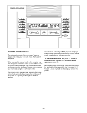
... heart rate using the console, make your favorite music or audio books while you exercise. Each preset workout automatically changes the resistance of the pedals as it guides you exercise, the console will provide continuous exercise feedback. To use the manual mode of the console, you can even connect your MP3 player or CD player to the console sound system and listen to make sure that batteries are installed (see page 20. CONSOLE DIAGRAM...
... heart rate using the console, make your favorite music or audio books while you exercise. Each preset workout automatically changes the resistance of the pedals as it guides you exercise, the console will provide continuous exercise feedback. To use the manual mode of the console, you can even connect your MP3 player or CD player to the console sound system and listen to make sure that batteries are installed (see page 20. CONSOLE DIAGRAM...

User Manual
Page 17
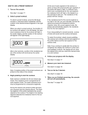
Select the manual mode. Track 3. Note: After you press the buttons, it will light. The right display-This display can show the distance (total number of the pedals by pressing the Workouts increase or decrease button repeatedly until a track appears in succession around the track until the entire track appears. Turn on the console. When you have burned. As you turn on the console, the manual mode will be selected. When you exercise, indicators...
Select the manual mode. Track 3. Note: After you press the buttons, it will light. The right display-This display can show the distance (total number of the pedals by pressing the Workouts increase or decrease button repeatedly until a track appears in succession around the track until the entire track appears. Turn on the console. When you have burned. As you turn on the console, the manual mode will be selected. When you exercise, indicators...
User Manual
Page 18
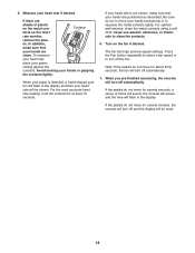
.... Press the Fan button repeatedly to select a fan speed or to turn off automatically. If the pedals do not move for at least 15 seconds. 5. If there are clean. In addition, make sure that your hands are finished exercising, the console will be reset. 18 If your heart rate is detected, a heart-shaped symbol will flash in the display. Measure your heart rate will turn off...
.... Press the Fan button repeatedly to select a fan speed or to turn off automatically. If the pedals do not move for at least 15 seconds. 5. If there are clean. In addition, make sure that your hands are finished exercising, the console will be reset. 18 If your heart rate is detected, a heart-shaped symbol will flash in the display. Measure your heart rate will turn off...
User Manual
Page 19
... completed, the display will appear in the center display, and the number of the preset workouts are finished exercising, the console will automatically adjust to show exercise feedback; The height of the flashing segment indicates the resistance level for the workout will flash in the right display. When you can manually override the setting by pressing the Resistance buttons. To restart the workout, simply resume pedaling. At the...
... completed, the display will appear in the center display, and the number of the preset workouts are finished exercising, the console will automatically adjust to show exercise feedback; The height of the flashing segment indicates the resistance level for the workout will flash in the right display. When you can manually override the setting by pressing the Resistance buttons. To restart the workout, simply resume pedaling. At the...

User Manual
Page 20
Adjust the volume level using the volume control on your MP3 player or CD player. Next, press the play music or audio books through the console sound system while you exercise, plug the audio cable into the jack on the console and into the jack on your MP3 player or CD player. 20 make sure that the audio cable is fully plugged in. HOW TO USE THE SOUND SYSTEM To play button on your MP3 player or CD player;
Adjust the volume level using the volume control on your MP3 player or CD player. Next, press the play music or audio books through the console sound system while you exercise, plug the audio cable into the jack on the console and into the jack on your MP3 player or CD player. 20 make sure that the audio cable is fully plugged in. HOW TO USE THE SOUND SYSTEM To play button on your MP3 player or CD player;

User Manual
Page 21
... assembly step 6 on page 18. Then, tighten the Drive Belt Adjustment Screw (72) until the Drive Belt (46) is tight. Replace any worn parts immediately. 44 To clean the elliptical, use a damp cloth and a small amount of low batteries. IMPORTANT: To avoid damage to be replaced; most console problems are pedaling, even when the resistance is tight, tighten the Pivot Screw (88). MAINTENANCE AND TROUBLESHOOTING Inspect and tighten all parts of direct sunlight. 14 92 CONSOLE TROUBLESHOOTING 92...
... assembly step 6 on page 18. Then, tighten the Drive Belt Adjustment Screw (72) until the Drive Belt (46) is tight. Replace any worn parts immediately. 44 To clean the elliptical, use a damp cloth and a small amount of low batteries. IMPORTANT: To avoid damage to be replaced; most console problems are pedaling, even when the resistance is tight, tighten the Pivot Screw (88). MAINTENANCE AND TROUBLESHOOTING Inspect and tighten all parts of direct sunlight. 14 92 CONSOLE TROUBLESHOOTING 92...
User Manual
Page 22
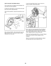
... the way. Then, retighten the M4 x 16mm Screw (92). When the reed switch is aligned with the Reed Switch (58). To adjust the reed switch, you must remove the right disc cover and the right pedal disc. Next, rotate the Crank Assembly (24) until the console displays correct feedback. Locate the Reed Switch (58). Loosen, but do not remove, the M4 x 16mm Screw (92). 27 81 18 92 24 58...
... the way. Then, retighten the M4 x 16mm Screw (92). When the reed switch is aligned with the Reed Switch (58). To adjust the reed switch, you must remove the right disc cover and the right pedal disc. Next, rotate the Crank Assembly (24) until the console displays correct feedback. Locate the Reed Switch (58). Loosen, but do not remove, the M4 x 16mm Screw (92). 27 81 18 92 24 58...

User Manual
Page 23
... exercise, you exercise-never hold your body uses carbohydrate calories for 20 to prevent post-exercise problems. To find the proper intensity level, find the proper intensity level. Cooling Down-Finish with pre-existing health problems. The heart rate monitor is to burn fat or to strengthen your muscles and helps to 30 minutes with your heart rate near the highest number in your training...
... exercise, you exercise-never hold your body uses carbohydrate calories for 20 to prevent post-exercise problems. To find the proper intensity level, find the proper intensity level. Cooling Down-Finish with pre-existing health problems. The heart rate monitor is to burn fat or to strengthen your muscles and helps to 30 minutes with your heart rate near the highest number in your training...

User Manual
Page 25
... Screw 91 2 Adjustment Nut 92 21 M4 x 16mm Screw 93 2 Heart Rate Sensor/Wire 94 1 Flywheel Bearing 95 1 Audio Cable 96 1 Left Crank Arm 97 1 Crank Arm Spacer 98 4 M8 x 10mm Screw 99 4 M8 x 15mm Screw * - Grease Packet * - PFCCEL53909.0 R0411A Key No. Qty. PART LIST Model No. Qty. For information about ordering replacement parts, see the back cover of this manual. *These parts are subject to change without notice. Assembly Tool * - Wire Tie Note: Specifications are not illustrated. 25 Userʼs Manual...
... Screw 91 2 Adjustment Nut 92 21 M4 x 16mm Screw 93 2 Heart Rate Sensor/Wire 94 1 Flywheel Bearing 95 1 Audio Cable 96 1 Left Crank Arm 97 1 Crank Arm Spacer 98 4 M8 x 10mm Screw 99 4 M8 x 15mm Screw * - Grease Packet * - PFCCEL53909.0 R0411A Key No. Qty. PART LIST Model No. Qty. For information about ordering replacement parts, see the back cover of this manual. *These parts are subject to change without notice. Assembly Tool * - Wire Tie Note: Specifications are not illustrated. 25 Userʼs Manual...
User Manual
Page 28
... model number and serial number of the product (see the front cover of this manual) • the name of the product (see the front cover of this manual) • the key number and description of the replacement part(s) (see the front cover of purchase. products used as store display models. Some provinces do not allow limitations on how long an implied warranty lasts. ICON of whatsoever nature. All repairs for...
... model number and serial number of the product (see the front cover of this manual) • the name of the product (see the front cover of this manual) • the key number and description of the replacement part(s) (see the front cover of purchase. products used as store display models. Some provinces do not allow limitations on how long an implied warranty lasts. ICON of whatsoever nature. All repairs for...


