User Manual
Page 2
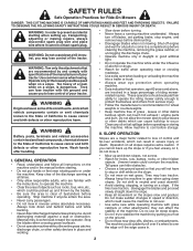
...instructions, to operate the machine. • Clear the area of objects such as rocks, toys, wire, etc., which can touch hot exhaust / engine parts and burn. If the tires lose traction, disengage the blades and proceed slowly straight down slopes. Do no use on a slope, is clear of ...running machine unattended. II. Do not shift to neutral and coast downhill. • Avoid starting . • Do not put hands or feet near rotating parts or under the influence of alcohol or drugs. • Watch for all instructions on the ground. • Do not mow near or crossing roadways. •...
...instructions, to operate the machine. • Clear the area of objects such as rocks, toys, wire, etc., which can touch hot exhaust / engine parts and burn. If the tires lose traction, disengage the blades and proceed slowly straight down slopes. Do no use on a slope, is clear of ...running machine unattended. II. Do not shift to neutral and coast downhill. • Avoid starting . • Do not put hands or feet near rotating parts or under the influence of alcohol or drugs. • Watch for all instructions on the ground. • Do not mow near or crossing roadways. •...
User Manual
Page 3
... carry passengers. • Do not mow in the watchful care of the mowing area and in safe working condition. • Never tamper with manufacturer's recommended parts, when necessary. • Mower blades are sharp. Always look down for another ride and be seriously injured or interfere with the engine running . • Check...
... carry passengers. • Do not mow in the watchful care of the mowing area and in safe working condition. • Never tamper with manufacturer's recommended parts, when necessary. • Mower blades are sharp. Always look down for another ride and be seriously injured or interfere with the engine running . • Check...
User Manual
Page 5
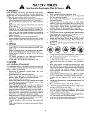
UNASSEMBLED PARTS Steering Wheel Steering Wheel Insert (1) Large Flat Washer (1) Hex Bolt 5/16-18 x 4 (1) 5/16 Lock Washer Steering Wheel Adapter Steering Boot Seat (1) Seat Steering Extension Shaft (1) Washer (1) Knob Keys (1) Oil Drain Tube For Future Use Slope Sheet (2) Keys 5
UNASSEMBLED PARTS Steering Wheel Steering Wheel Insert (1) Large Flat Washer (1) Hex Bolt 5/16-18 x 4 (1) 5/16 Lock Washer Steering Wheel Adapter Steering Boot Seat (1) Seat Steering Extension Shaft (1) Washer (1) Knob Keys (1) Oil Drain Tube For Future Use Slope Sheet (2) Keys 5

User Manual
Page 6
...located between terminals) charge battery for minimum of one hour at the factory with exception of your tractor all accessible loose parts and parts cartons from the cardboard packing. Use the correct tools as necessary to cardboard packing and set will make assembly easier....6 Remove adjustment knob and flat washer securing seat to insure proper tightness. TO REMOVE TRACTOR FROM CARTON UNPACK CARTON • Remove all parts and hardware you are horizontal (left unassembled for assembly of steering wheel. • Remove protective materials from tractor hood and grill. To...
...located between terminals) charge battery for minimum of one hour at the factory with exception of your tractor all accessible loose parts and parts cartons from the cardboard packing. Use the correct tools as necessary to cardboard packing and set will make assembly easier....6 Remove adjustment knob and flat washer securing seat to insure proper tightness. TO REMOVE TRACTOR FROM CARTON UNPACK CARTON • Remove all parts and hardware you are horizontal (left unassembled for assembly of steering wheel. • Remove protective materials from tractor hood and grill. To...
User Manual
Page 7
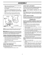
..." in the Service and Adjustments section of this manual. PLEASE REVIEW THE FOLLOWING CHECKLIST: ✓ All assembly instructions have been completed. ✓ No remaining loose parts in carton. ✓ Battery is properly prepared and charged. (Minimum 1 hour at the factory). ✓ Be sure mower deck is properly leveled side-to-side...
..." in the Service and Adjustments section of this manual. PLEASE REVIEW THE FOLLOWING CHECKLIST: ✓ All assembly instructions have been completed. ✓ No remaining loose parts in carton. ✓ Battery is properly prepared and charged. (Minimum 1 hour at the factory). ✓ Be sure mower deck is properly leveled side-to-side...
User Manual
Page 15
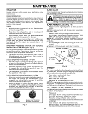
... manual). IMPORTANT: SPECIAL BLADE BOLT HEAT TREATED. Do not attempt to "leak" power. CAUTION: Use only a replacement blade approved by the manufacturer of your local parts dealer. Using a blade not approved by the manufacturer of this manual). 15 TO CLEAN BATTERY AND TERMINALS Corrosion and dirt on a level, dry concrete or...
... manual). IMPORTANT: SPECIAL BLADE BOLT HEAT TREATED. Do not attempt to "leak" power. CAUTION: Use only a replacement blade approved by the manufacturer of your local parts dealer. Using a blade not approved by the manufacturer of this manual). 15 TO CLEAN BATTERY AND TERMINALS Corrosion and dirt on a level, dry concrete or...
User Manual
Page 18
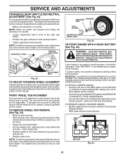
... position. • Place attachment clutch in "DISENGAGED" position. • Turn ignition key to "STOP" and remove key. • Make sure the blades and all moving parts have completely stopped. • Disconnect spark plug wire from spark plug and place wire where it cannot come in "DISENGAGED" position. • Move attachment lift...
... position. • Place attachment clutch in "DISENGAGED" position. • Turn ignition key to "STOP" and remove key. • Make sure the blades and all moving parts have completely stopped. • Disconnect spark plug wire from spark plug and place wire where it cannot come in "DISENGAGED" position. • Move attachment lift...
User Manual
Page 21
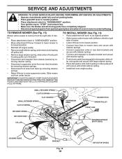
... punctures and prevent flat tires due to start the engine, it should be in neutral when the gear shift lever is normal. If your local parts dealer. NOTE: When the tractor rear wheels move mower deck height to right) when wheels are used for emergency starting, follow this manual. ADJUSTMENT BOLT...
... punctures and prevent flat tires due to start the engine, it should be in neutral when the gear shift lever is normal. If your local parts dealer. NOTE: When the tractor rear wheels move mower deck height to right) when wheels are used for emergency starting, follow this manual. ADJUSTMENT BOLT...
User Manual
Page 23
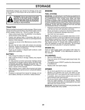
... during storage. placement instructions in the Service and Adjustments section of this manual. • Be sure that does not retain moisture. Inspect moving parts for damage, breakage and wear. BATTERY • Fully charge the battery for storage. • After a period of this manual). •.... • Use fresh fuel next season. ENGINE FUEL SYSTEM IMPORTANT: IT IS IMPORTANT TO PREVENT GUM DEPOSITS FROM FORMING IN ESSENTIAL FUEL SYSTEM PARTS SUCH AS CARBURETOR, FUEL FILTER, FUEL HOSE, OR TANK DURING STORAGE. Replace if necessary. • Touch up all dirt, grease, leaves...
... during storage. placement instructions in the Service and Adjustments section of this manual. • Be sure that does not retain moisture. Inspect moving parts for damage, breakage and wear. BATTERY • Fully charge the battery for storage. • After a period of this manual). •.... • Use fresh fuel next season. ENGINE FUEL SYSTEM IMPORTANT: IT IS IMPORTANT TO PREVENT GUM DEPOSITS FROM FORMING IN ESSENTIAL FUEL SYSTEM PARTS SUCH AS CARBURETOR, FUEL FILTER, FUEL HOSE, OR TANK DURING STORAGE. Replace if necessary. • Touch up all dirt, grease, leaves...
User Manual
Page 25
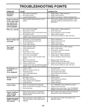
...engaged. 1. Faulty light switch. 4. Poor cable connections. 3. Faulty regulator (if so equipped). 4. Faulty alternator. 1. Tighten loose part(s). Clean underside of grass, leaves and trash under mower. 7. Poor grass discharge Headlight(s) not working (if so equipped) 1. Worn.... 1. Debris on steering plate (if equipped). 2. TROUBLESHOOTING POINTS PROBLEM Excessive vibration CAUSE 1. Tighten blade bolt. 2. Replace damaged parts. uneven Mower blades will not charge 1. Frozen idler pulley. 4. Level mower deck. 3. Travel speed too fast. 2. Shift ...
...engaged. 1. Faulty light switch. 4. Poor cable connections. 3. Faulty regulator (if so equipped). 4. Faulty alternator. 1. Tighten loose part(s). Clean underside of grass, leaves and trash under mower. 7. Poor grass discharge Headlight(s) not working (if so equipped) 1. Worn.... 1. Debris on steering plate (if equipped). 2. TROUBLESHOOTING POINTS PROBLEM Excessive vibration CAUSE 1. Tighten blade bolt. 2. Replace damaged parts. uneven Mower blades will not charge 1. Frozen idler pulley. 4. Level mower deck. 3. Travel speed too fast. 2. Shift ...
User Manual
Page 28
...as defined in materials and workmanship. Please refer to the engine, transaxle/transmission components, battery (except as noted below) or components parts thereof. Exclusions: Excluded from this Warranty, please contact: HOP Outdoor Products Customer Service Dept. 9335 Harris Corners Parkway Charlotte, NC...and normal maintenance. 7. This warranty does not apply to the applicable manufacturer's warranty on these items. 2. The Warranty period for parts or labor incurred in manufacture, during the first ninety (90) days of the purchaser. This Warranty applies only to 90 days ...
...as defined in materials and workmanship. Please refer to the engine, transaxle/transmission components, battery (except as noted below) or components parts thereof. Exclusions: Excluded from this Warranty, please contact: HOP Outdoor Products Customer Service Dept. 9335 Harris Corners Parkway Charlotte, NC...and normal maintenance. 7. This warranty does not apply to the applicable manufacturer's warranty on these items. 2. The Warranty period for parts or labor incurred in manufacture, during the first ninety (90) days of the purchaser. This Warranty applies only to 90 days ...
Parts Manual
Page 1
IMPORTANT MANUAL DO NOT THROW AWAY 5000 REPAIR PARTS MANUAL MODEL: PO14542LT LAWN TRACTOR WARNING: Read this Manual and follow all Warnings and Safety Instructions. Failure to do so can result in serious injury. ALWAYS WEAR EYE PROTECTION DURING OPERATION Visit our website: www.poulan.com 440627
IMPORTANT MANUAL DO NOT THROW AWAY 5000 REPAIR PARTS MANUAL MODEL: PO14542LT LAWN TRACTOR WARNING: Read this Manual and follow all Warnings and Safety Instructions. Failure to do so can result in serious injury. ALWAYS WEAR EYE PROTECTION DURING OPERATION Visit our website: www.poulan.com 440627

Parts Manual
Page 2
Some hardware and parts are drawn larger in order to assemble or disassemble the tractor. Each tractor has its own model number. When ordering parts, always give the following information: • Product - The illustrations may or may not represent the actual... the seat. The model number for your tractor can be found on his/her tractor when ordering repair parts. "TRACTOR" • MODEL NUMBER - "PO14542LT (96012011900)" • Part Number • Part Description TABLE OF CONTENTS SCHEMATIC ...3 ELECTRICAL ...4-5 CHASSIS ...6-7 DRIVE...8-9 ENGINE ...10-11 STEERING ...12-13 ...
Some hardware and parts are drawn larger in order to assemble or disassemble the tractor. Each tractor has its own model number. When ordering parts, always give the following information: • Product - The illustrations may or may not represent the actual... the seat. The model number for your tractor can be found on his/her tractor when ordering repair parts. "TRACTOR" • MODEL NUMBER - "PO14542LT (96012011900)" • Part Number • Part Description TABLE OF CONTENTS SCHEMATIC ...3 ELECTRICAL ...4-5 CHASSIS ...6-7 DRIVE...8-9 ENGINE ...10-11 STEERING ...12-13 ...

Parts Manual
Page 5
... Hex 1/4-20 42 532 13 15-63 Cover Terminal Red 43 532 19 25-07 Solenoid 79 532 17 52-42 Socket Asm. MODEL NUMBER PO14542LT (96012011900), PRODUCT NO. 960 12 01-19 ELECTRICAL KEY...
... Hex 1/4-20 42 532 13 15-63 Cover Terminal Red 43 532 19 25-07 Solenoid 79 532 17 52-42 Socket Asm. MODEL NUMBER PO14542LT (96012011900), PRODUCT NO. 960 12 01-19 ELECTRICAL KEY...

Parts Manual
Page 7
... Plug Button Blk 359 Dia Choke - - 532 18 78-01 Plug Dome Plastic NOTE: All component dimensions given in U.S. MODEL NUMBER PO14542LT (96012011900), PRODUCT NO. 960 12 01-19 CHASSIS KEY PART NO. NO. inches 1 inch = 25.4 mm. 7 DESCRIPTION 1 532 17 46-19 Chassis 2 532 17 65-54 Drawbar, Stretch 5 532 15...
... Plug Button Blk 359 Dia Choke - - 532 18 78-01 Plug Dome Plastic NOTE: All component dimensions given in U.S. MODEL NUMBER PO14542LT (96012011900), PRODUCT NO. 960 12 01-19 CHASSIS KEY PART NO. NO. inches 1 inch = 25.4 mm. 7 DESCRIPTION 1 532 17 46-19 Chassis 2 532 17 65-54 Drawbar, Stretch 5 532 15...

Parts Manual
Page 9
...3/8-16 x 1-1/4 57 532 13 82-55 V-Belt Ground Drive 62 532 12 48-72 Cover Pedal Blk Round KEY PART NO. TRACTOR - NO. DESCRIPTION 63 532 17 54-10 Engine Pulley 64 532 17 39-37 Bolt Hex 65 810...RdHd 3/8-16 unc x 1-3/4 Gr. 5 NOTE: All component dimensions given in U.S. NO. DESCRIPTION 1 Transaxle Peerless 206-545C (165670) (Order parts from transaxle manufacturer) 2 532 14 66-82 Spring Return Brake T/a Zinc 3 532 12 36-66 Pulley Transaxle 18" Tires 4 812 00...05 Retainer Belt Style Spring 50 872 11 06-12 Bolt Carr. MODEL NUMBER PO14542LT (96012011900), PRODUCT NO. 960 12 01-19 DRIVE KEY...
...3/8-16 x 1-1/4 57 532 13 82-55 V-Belt Ground Drive 62 532 12 48-72 Cover Pedal Blk Round KEY PART NO. TRACTOR - NO. DESCRIPTION 63 532 17 54-10 Engine Pulley 64 532 17 39-37 Bolt Hex 65 810...RdHd 3/8-16 unc x 1-3/4 Gr. 5 NOTE: All component dimensions given in U.S. NO. DESCRIPTION 1 Transaxle Peerless 206-545C (165670) (Order parts from transaxle manufacturer) 2 532 14 66-82 Spring Return Brake T/a Zinc 3 532 12 36-66 Pulley Transaxle 18" Tires 4 812 00...05 Retainer Belt Style Spring 50 872 11 06-12 Bolt Carr. MODEL NUMBER PO14542LT (96012011900), PRODUCT NO. 960 12 01-19 DRIVE KEY...

Parts Manual
Page 11
...DESCRIPTION 1 532 17 05-51 Control Th/ch Flag 2 817 72 04-08 Screw Hex Thd Cut 1/4-20 x 1/2 3 Engine, B&S 31A507-4405-G1(440006) (Order parts from engine manufacturer) 4 532 13 73-52 Muffler Exhaust B&S 13 532 16 52-91 Gasket Eng 1 313 Id Tin Plated 23 532 16 98-37...component dimensions given in accordance with SAE J1995 (Revision 2002-05). horsepower values are derived at 3060 RPM; MODEL NUMBER PO14542LT (96012011900), PRODUCT NO. 960 12 01-19 ENGINE KEY PART NO. Given both the wide array of environmental issues applicable to operating the equipment, the gas engine will be lower...
...DESCRIPTION 1 532 17 05-51 Control Th/ch Flag 2 817 72 04-08 Screw Hex Thd Cut 1/4-20 x 1/2 3 Engine, B&S 31A507-4405-G1(440006) (Order parts from engine manufacturer) 4 532 13 73-52 Muffler Exhaust B&S 13 532 16 52-91 Gasket Eng 1 313 Id Tin Plated 23 532 16 98-37...component dimensions given in accordance with SAE J1995 (Revision 2002-05). horsepower values are derived at 3060 RPM; MODEL NUMBER PO14542LT (96012011900), PRODUCT NO. 960 12 01-19 ENGINE KEY PART NO. Given both the wide array of environmental issues applicable to operating the equipment, the gas engine will be lower...

Parts Manual
Page 13
inches 1 inch = 25.4 mm. 13 TRACTOR - NO. MODEL NUMBER PO14542LT (96012011900), PRODUCT NO. 960 12 01-19 STEERING KEY PART NO. DESCRIPTION 1 532 42 45-43 Wheel Steering 2 532 41 81-68 Axle Asm 3 532 16 98-40 Spindle Asm LH 4 532 16 98-39 ...
inches 1 inch = 25.4 mm. 13 TRACTOR - NO. MODEL NUMBER PO14542LT (96012011900), PRODUCT NO. 960 12 01-19 STEERING KEY PART NO. DESCRIPTION 1 532 42 45-43 Wheel Steering 2 532 41 81-68 Axle Asm 3 532 16 98-40 Spindle Asm LH 4 532 16 98-39 ...

Parts Manual
Page 14
... Ga. 532 19 55-30 Pan Pnt Seat 532 16 63-69 Knob Seat 532 17 46-48 Bracket Pnt Mounting Switch KEY PART NO. TRACTOR - MODEL NUMBER PO14542LT (96012011900), PRODUCT NO. 960 12 01-19 SEAT 1 14 24 8 9 7 10 5 8 9 7 5 6 22 2 21 16 25 15 11 4 13 17 12 3 seat-stlt_knob_1 KEY...
... Ga. 532 19 55-30 Pan Pnt Seat 532 16 63-69 Knob Seat 532 17 46-48 Bracket Pnt Mounting Switch KEY PART NO. TRACTOR - MODEL NUMBER PO14542LT (96012011900), PRODUCT NO. 960 12 01-19 SEAT 1 14 24 8 9 7 10 5 8 9 7 5 6 22 2 21 16 25 15 11 4 13 17 12 3 seat-stlt_knob_1 KEY...
Parts Manual
Page 15
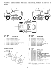
..., Ins Str Wh 9 532 43 19-86 Decal, Fender WHEELS & TIRES 1 2 5,8 4,10 7 6 3,9 11 wheel_1 KEY PART NO. NO. MODEL NUMBER PO14542LT (96012011900), PRODUCT NO. 960 12 01-19 DECALS 7 12 2 12 6 15 9 5 11 1 4 11 5 3 10 KEY PART NO. NO. TRACTOR - DESCRIPTION 10 532 16 03-96 Decal, V-Belt Sch. 11 532 43 84...-91 Pad Footrest LH - - 532 13 83-11 Decal, Handle Lft Height Adj. - - 532 44 06-26 Manual, Operator's - - 532 44 06-27 Manual, Parts KEY PART NO. DESCRIPTION 1 532 05 91-92 Cap, Tire Valve 2 532 06 51-39 Stem, Valve 3 532 10 62-22 Tire, Front 4 532 05 99-04...
..., Ins Str Wh 9 532 43 19-86 Decal, Fender WHEELS & TIRES 1 2 5,8 4,10 7 6 3,9 11 wheel_1 KEY PART NO. NO. MODEL NUMBER PO14542LT (96012011900), PRODUCT NO. 960 12 01-19 DECALS 7 12 2 12 6 15 9 5 11 1 4 11 5 3 10 KEY PART NO. NO. TRACTOR - DESCRIPTION 10 532 16 03-96 Decal, V-Belt Sch. 11 532 43 84...-91 Pad Footrest LH - - 532 13 83-11 Decal, Handle Lft Height Adj. - - 532 44 06-26 Manual, Operator's - - 532 44 06-27 Manual, Parts KEY PART NO. DESCRIPTION 1 532 05 91-92 Cap, Tire Valve 2 532 06 51-39 Stem, Valve 3 532 10 62-22 Tire, Front 4 532 05 99-04...


