Service Manual
Page 1
... T-FZK MAY 1997 Printed in Belgium KU KC SD KU/CA AC120V AC120V AC110V/1 20 -127V/220Vi240V AC120V With the volta e selector CONTENTS 1. SAFETY INFORMATION . 2. SCHEMATIC DIAGRAM 4. ADJUSTMENT 7. EXPLODED VIEWS AND PARTS LIST 3. PCB CONNECTION DIAGRAM 5. R RV1 7 7 0 VSX-07TX VSX-09TX THIS MANUAL IS APPLICABLE TO THE FOLLOWING MODEL(S) AND TYPE(S). GENERAL INFORMATION. 7.1 PARTS 7.1. 1 IC 7 .1.2 DISPLAY . 7.2 BLOCK DIAGRAM . 7.3 REMOTE CONT ROL UNIT 8. PIONEER ELECTRONIC [EUROPEI N.V.
... T-FZK MAY 1997 Printed in Belgium KU KC SD KU/CA AC120V AC120V AC110V/1 20 -127V/220Vi240V AC120V With the volta e selector CONTENTS 1. SAFETY INFORMATION . 2. SCHEMATIC DIAGRAM 4. ADJUSTMENT 7. EXPLODED VIEWS AND PARTS LIST 3. PCB CONNECTION DIAGRAM 5. R RV1 7 7 0 VSX-07TX VSX-09TX THIS MANUAL IS APPLICABLE TO THE FOLLOWING MODEL(S) AND TYPE(S). GENERAL INFORMATION. 7.1 PARTS 7.1. 1 IC 7 .1.2 DISPLAY . 7.2 BLOCK DIAGRAM . 7.3 REMOTE CONT ROL UNIT 8. PIONEER ELECTRONIC [EUROPEI N.V.
Service Manual
Page 2
... this Service Manual. Improperly performed repairs can be above 0.5 rnA Test all exposed Irlslal surfaces 0 Also test with plug reversed (Using AC adapter plug as Simpson Model 229-2 or equivalent between the earth ground and all exposed metal parts of the product and may cause birth defects or other reproductive harm (California Health & Safety Code, Section 25249.5). Device under review and new instructions...
... this Service Manual. Improperly performed repairs can be above 0.5 rnA Test all exposed Irlslal surfaces 0 Also test with plug reversed (Using AC adapter plug as Simpson Model 229-2 or equivalent between the earth ground and all exposed metal parts of the product and may cause birth defects or other reproductive harm (California Health & Safety Code, Section 25249.5). Device under review and new instructions...
Service Manual
Page 3
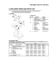
VSX-D906S, VSX-07TX, VSX-09TX 2. found on some component parts indicates rhe importance of the safen' factor of identical designation. ~ Screws adj acent to W nrark on product are not in our Master Spare Parts Lisr. ~ The /h . VSX117) Remote Conuol Unit (CU - marl. T/terefore, when replacing, be stoa to 11 Sub PQ(I FM Antenna ADH 1015 NSP 2 AlkalineDryCellBatteries(LR6.AA)AEX1007 3 Operating Instructions See Contrast...
VSX-D906S, VSX-07TX, VSX-09TX 2. found on some component parts indicates rhe importance of the safen' factor of identical designation. ~ Screws adj acent to W nrark on product are not in our Master Spare Parts Lisr. ~ The /h . VSX117) Remote Conuol Unit (CU - marl. T/terefore, when replacing, be stoa to 11 Sub PQ(I FM Antenna ADH 1015 NSP 2 AlkalineDryCellBatteries(LR6.AA)AEX1007 3 Operating Instructions See Contrast...

Service Manual
Page 10
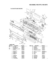
... 14 15 Descri tion Volume Ring Center Panel Name Piste Power Button 5 -Action Button Parts No. VSX-D906S, VSX-07TX, VSX-09TX 21 2.4 FRONT PANEL SECTION For VSX-D906S ONLY 13 19 0 14 oQ 21 21 21 Cutti.n7g o g o hooiQ+oo0 w+4o 17 o 4o 16 21 . UCOM ASSY 3 RMC ASSY 4 P OWER SWITCH ASSY 5 FFC 29P Parts No. Symbol & Description VSX-D906S/Ku Part No VSX-D906S/KC VSX-D906S/SD Remarks 32 NSP...
... 14 15 Descri tion Volume Ring Center Panel Name Piste Power Button 5 -Action Button Parts No. VSX-D906S, VSX-07TX, VSX-09TX 21 2.4 FRONT PANEL SECTION For VSX-D906S ONLY 13 19 0 14 oQ 21 21 21 Cutti.n7g o g o hooiQ+oo0 w+4o 17 o 4o 16 21 . UCOM ASSY 3 RMC ASSY 4 P OWER SWITCH ASSY 5 FFC 29P Parts No. Symbol & Description VSX-D906S/Ku Part No VSX-D906S/KC VSX-D906S/SD Remarks 32 NSP...
Service Manual
Page 11
... 12 Mark No . Descri tion 16 Enter Button 17 PVC Panel 18 Function Button 19 I KEY ASSY 2 FL -UCOM ASSY 3 RMC ASSY 4 PO WER SW IT CH ASSY 5 FFC 29P Parts No. Q + 27 0 QQ Qo o .+Q 16 22 17 ~ 0 20 .S' 28 la 26 28 - @ - For VSX-OTtX AND VSX-09TX VSX-D906S, VSX-07TX, VSX-09TX 21 19 Qw O oo, O oo, 25...
... 12 Mark No . Descri tion 16 Enter Button 17 PVC Panel 18 Function Button 19 I KEY ASSY 2 FL -UCOM ASSY 3 RMC ASSY 4 PO WER SW IT CH ASSY 5 FFC 29P Parts No. Q + 27 0 QQ Qo o .+Q 16 22 17 ~ 0 20 .S' 28 la 26 28 - @ - For VSX-OTtX AND VSX-09TX VSX-D906S, VSX-07TX, VSX-09TX 21 19 Qw O oo, O oo, 25...
Service Manual
Page 12
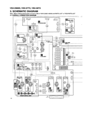
... FAN AXM70 12 4 5m 5 551 51063- 0905 5 505 m5 m S-VIDEO ASSY :* Q PRE-OUT a sR ASSY SCHEMATIC DIAGRAM Note : When ordering service parts, be sure to refer to "EXPLODED VIEWS and PARTS LIST" or SPCB PARTS LIST" 3.1 OVERALL CONNECTION DIAGRAM 0 CD CK D 10 III X CD 52044- 2945 51065- 8985 51063- ...100 J21 ( 015A04 200 EI KP E4 POWER SWITCH ASSY V-AMP ASSY ADJX736eee SD AND KU/CA TYPES J'3' D15A03 ( 01I5A515)) 51063- 0305 I 51 063-1 5$5 g» LIMITTER ASSY 4 D 52044- 2945 45551 CONNECTION ASSY 88208TA1 9 KPE 3 K M 208TA9 MASTER VR ASST J15 D15A05 125 KPE9 5106'3- ...
... FAN AXM70 12 4 5m 5 551 51063- 0905 5 505 m5 m S-VIDEO ASSY :* Q PRE-OUT a sR ASSY SCHEMATIC DIAGRAM Note : When ordering service parts, be sure to refer to "EXPLODED VIEWS and PARTS LIST" or SPCB PARTS LIST" 3.1 OVERALL CONNECTION DIAGRAM 0 CD CK D 10 III X CD 52044- 2945 51065- 8985 51063- ...100 J21 ( 015A04 200 EI KP E4 POWER SWITCH ASSY V-AMP ASSY ADJX736eee SD AND KU/CA TYPES J'3' D15A03 ( 01I5A515)) 51063- 0305 I 51 063-1 5$5 g» LIMITTER ASSY 4 D 52044- 2945 45551 CONNECTION ASSY 88208TA1 9 KPE 3 K M 208TA9 MASTER VR ASST J15 D15A05 125 KPE9 5106'3- ...
Service Manual
Page 33
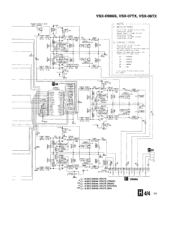
... 1 kl el r ID J R9684 r 22k Jsc sses Rge gg 1 I 88 (F) L 9 6 8 1 Q9681 2 56 3 326 R aces ( 4. 7k O TL I II OO O O ~: AUDIO SIGNAL ROUTE (~ ~ : A UD IO SIGNAL ROUTE (FRONT) MR o D ot h e s e o t ed R a t ed power . l ess n l ess n i sse I / 25 YF AZ C 964 2 R9 64 1 1 1 8 / 1 6 3. CKSQYF Y B . . . I 2. C a p a c ... Cpu)I Olul L CC C 9632 R963 1 J 1 8/ 1 6 5. 5 k rl ID Z r J a ) asst I STORS U t. k (I Sk V+15 C9681 8. VSX-D906S, VSX-07TX, VSX-09TX R9 4 8 6 2 PD 6 8 1A Q / R 27 k Qg 4 82 V+5A C 968 2 1 18 /I 6 IeD r all 0 IS R9 68 1 I I , M .
... 1 kl el r ID J R9684 r 22k Jsc sses Rge gg 1 I 88 (F) L 9 6 8 1 Q9681 2 56 3 326 R aces ( 4. 7k O TL I II OO O O ~: AUDIO SIGNAL ROUTE (~ ~ : A UD IO SIGNAL ROUTE (FRONT) MR o D ot h e s e o t ed R a t ed power . l ess n l ess n i sse I / 25 YF AZ C 964 2 R9 64 1 1 1 8 / 1 6 3. CKSQYF Y B . . . I 2. C a p a c ... Cpu)I Olul L CC C 9632 R963 1 J 1 8/ 1 6 5. 5 k rl ID Z r J a ) asst I STORS U t. k (I Sk V+15 C9681 8. VSX-D906S, VSX-07TX, VSX-09TX R9 4 8 6 2 PD 6 8 1A Q / R 27 k Qg 4 82 V+5A C 968 2 1 18 /I 6 IeD r all 0 IS R9 68 1 I I , M .

Service Manual
Page 43
... AKX1008 220.240V J Dezzeees I SD TYPE ONLY I 4 AC POWER CORD 1 21 A PDGIOI5 IKU AND KC TYPES) C 1 20 V... S C N15 1 IL O Z 3 CAUT I ON FOR CONT I NUEO PROTECT I ON AGA I NST R I SK OF F I RE REPLACE ONL Y W I T H SAME T YPE NO . 4'3100 I MF D BY L I TTEL.FUSE I N K FO R I C 1 0 3 ~ T RANS~ EO oweEJELIMI...lllll ~ NOTE F OR F USE R EPLACEMENT CA U T ! O J1053 /41 47 + POWER SUPPLY ASSY (AWZ8792 : KU ...SUB POWER TRANSFORMER ATT1123 : KU, KC AND K U/CA TYPES / S I RE . FOR CONT)NUEO PROTECT)ON AGAINST RISK OF F)RE R EPLACE ONLY W) T H SAME TYPE ANO RATINGS ONLY . VSX-D906S, VSX-07TX, VSX...
... AKX1008 220.240V J Dezzeees I SD TYPE ONLY I 4 AC POWER CORD 1 21 A PDGIOI5 IKU AND KC TYPES) C 1 20 V... S C N15 1 IL O Z 3 CAUT I ON FOR CONT I NUEO PROTECT I ON AGA I NST R I SK OF F I RE REPLACE ONL Y W I T H SAME T YPE NO . 4'3100 I MF D BY L I TTEL.FUSE I N K FO R I C 1 0 3 ~ T RANS~ EO oweEJELIMI...lllll ~ NOTE F OR F USE R EPLACEMENT CA U T ! O J1053 /41 47 + POWER SUPPLY ASSY (AWZ8792 : KU ...SUB POWER TRANSFORMER ATT1123 : KU, KC AND K U/CA TYPES / S I RE . FOR CONT)NUEO PROTECT)ON AGAINST RISK OF F)RE R EPLACE ONLY W) T H SAME TYPE ANO RATINGS ONLY . VSX-D906S, VSX-07TX, VSX...
Service Manual
Page 47
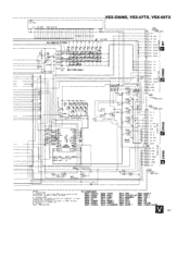
...ohm. SW 6 O. R E S I STORS i nd i c a t e d n ohm I IIAZZ D 15A1 2 - 2 58 - 265 1 FL 2 FL 1 -VF DG 0 + 5V ts ST. +5V FAN RY. S818 MPX S825 AM 38 12 : RESET 3819 SP A S826 FM 38 13 : DIRECT 6 820 SP B S8 27 LIST IN 3814 : LOUDNESS 882 1 BASS - S850 TUNER...DVD/TV S802 : LD/SAT S803 : VIDEO S804 : CD 5805 : TUNER S806 : TAPE2 5807 : PHONO S808 : TAPE1 S815 DRC S822 BASS+ S809: VCR1 S8 16 SYS SET...T 3 1 - PROT HP. VBBI A AV 78 3 7 ( F L HOLDER sl Sl m e R6 5 5 1K R656 1K 1VSX-D906S, VSX-07TX, YSX-09TX I I PNB14 29 - 8 ) I KU AND KC TYPES 1 '11 3 6 765 3 2 6 7 8 9 ...
...ohm. SW 6 O. R E S I STORS i nd i c a t e d n ohm I IIAZZ D 15A1 2 - 2 58 - 265 1 FL 2 FL 1 -VF DG 0 + 5V ts ST. +5V FAN RY. S818 MPX S825 AM 38 12 : RESET 3819 SP A S826 FM 38 13 : DIRECT 6 820 SP B S8 27 LIST IN 3814 : LOUDNESS 882 1 BASS - S850 TUNER...DVD/TV S802 : LD/SAT S803 : VIDEO S804 : CD 5805 : TUNER S806 : TAPE2 5807 : PHONO S808 : TAPE1 S815 DRC S822 BASS+ S809: VCR1 S8 16 SYS SET...T 3 1 - PROT HP. VBBI A AV 78 3 7 ( F L HOLDER sl Sl m e R6 5 5 1K R656 1K 1VSX-D906S, VSX-07TX, YSX-09TX I I PNB14 29 - 8 ) I KU AND KC TYPES 1 '11 3 6 765 3 2 6 7 8 9 ...

Service Manual
Page 51
...are 2 effective digits (any digit apart from 0), such as shown in our Master Spare Parts List. ~ The 4 m ark found on some component parts indicares the i nponance of the safety factor of identical designation. ~ When ordering resistors, first convert resistance values into code fornt as 560 ohrn and 47k ohm (tolerance is ...AW Z8874 AW K 7368 AWZ8732 AW Z 8734 AWZ8735 AWZ8736 AWZ8733 AW Z 88 19 AWZ8874 NSP POWER AMP ASSY L- Therefore, when replacing, be sure to use parts of the part. CURR DRIVE ASSY VOLTAGE AMP ASSY AW K 7385 AW Z 87 17 AWZ8776 AW K7385 AW Z 87 17 AWZ8776 AW ...
...are 2 effective digits (any digit apart from 0), such as shown in our Master Spare Parts List. ~ The 4 m ark found on some component parts indicares the i nponance of the safety factor of identical designation. ~ When ordering resistors, first convert resistance values into code fornt as 560 ohrn and 47k ohm (tolerance is ...AW Z8874 AW K 7368 AWZ8732 AW Z 8734 AWZ8735 AWZ8736 AWZ8733 AW Z 88 19 AWZ8874 NSP POWER AMP ASSY L- Therefore, when replacing, be sure to use parts of the part. CURR DRIVE ASSY VOLTAGE AMP ASSY AW K 7385 AW Z 87 17 AWZ8776 AW K7385 AW Z 87 17 AWZ8776 AW ...
Service Manual
Page 64
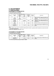
... Frequency Display TUNED IND. Ad j u s tment Title Center Adjustment Front End Sensitivity adjustment FM SG ( lkHz. e7SkHz dev.) Frequency (M Hz) Level (dBlt V) 98 Non modulation 80 or more 98 Low input (0 to light up . Notes: ~ Befo re adj usnng, make sure there is a gap between L6101 and L6102 . Lighting Level 999a ~ 47(e2dB) 999kHzv' v/ t For the area using /OkHz step, frequencies should be 1000kHz Adjustment Location Specifications...
... Frequency Display TUNED IND. Ad j u s tment Title Center Adjustment Front End Sensitivity adjustment FM SG ( lkHz. e7SkHz dev.) Frequency (M Hz) Level (dBlt V) 98 Non modulation 80 or more 98 Low input (0 to light up . Notes: ~ Befo re adj usnng, make sure there is a gap between L6101 and L6102 . Lighting Level 999a ~ 47(e2dB) 999kHzv' v/ t For the area using /OkHz step, frequencies should be 1000kHz Adjustment Location Specifications...
Service Manual
Page 68
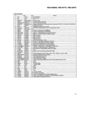
.../SCK I 26 SYNC.DEC PB6/SC I TUN ER : TUNER input. (L: T UNED)/JOG2 : Port data input Detection of AMP power error, A/D input. Port data input/TUNER: Stereo input (L: Receiving broadcasting in the main unit fmm AC3. (L: Request for communications with AC3 IC module. 5V. 29 V OL DOW N 30 PEAK.LEV PAO/ANO PA I/AN I 0 Master Volume (elecuically operated) DOW N output. 3 1 9K/I OK 32 P A2/A N 2 P A3/A N 3 Switching frequency steps of LEF...
.../SCK I 26 SYNC.DEC PB6/SC I TUN ER : TUNER input. (L: T UNED)/JOG2 : Port data input Detection of AMP power error, A/D input. Port data input/TUNER: Stereo input (L: Receiving broadcasting in the main unit fmm AC3. (L: Request for communications with AC3 IC module. 5V. 29 V OL DOW N 30 PEAK.LEV PAO/ANO PA I/AN I 0 Master Volume (elecuically operated) DOW N output. 3 1 9K/I OK 32 P A2/A N 2 P A3/A N 3 Switching frequency steps of LEF...
Service Manual
Page 69
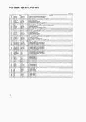
.... Audio mute ON/OFF. 0 Strobe output for TC9299. 0 Strobe output for M663 1) . )C output enable signal for TC9162 and TC9164. Clock for IC. LM7001 (T UNER) control . 0 Tuner mute ON/OFF. 0 Data for IC. control. 0 IC module reset output for AC3. 0 Master Volume (electrically operated) UP output. 0 K EY scan output I l . 0 Segment output I/ KEY scan output 10. 0 Segment output 2/KEY scan output 9. 0 Segment output 3/KEY scan output 8. 0 Segment output 4/KEY scan output 7. 0 Segment output S/KEY scan output 6. 0 Segment output...
.... Audio mute ON/OFF. 0 Strobe output for TC9299. 0 Strobe output for M663 1) . )C output enable signal for TC9162 and TC9164. Clock for IC. LM7001 (T UNER) control . 0 Tuner mute ON/OFF. 0 Data for IC. control. 0 IC module reset output for AC3. 0 Master Volume (electrically operated) UP output. 0 K EY scan output I l . 0 Segment output I/ KEY scan output 10. 0 Segment output 2/KEY scan output 9. 0 Segment output 3/KEY scan output 8. 0 Segment output 4/KEY scan output 7. 0 Segment output S/KEY scan output 6. 0 Segment output...
Service Manual
Page 70
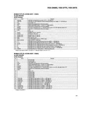
.... LED lights up when function is VIDEO. LED lights up if AC3 signal from M66311. 99 H: relay ON Speaker B relay. After that . Strobe line for communications with microcomputer. LED lights up when function is PHONO. LED lights up . Fixed to "H" . GND 10 F ixed to -H". H : relay ON R/C relay. L ; VSX-D906S, VSX-07TX, VSX-09TX ~ M66311FP (FL-UCOM ASSY : IC803) ~ LED DRIVER ~ Pin Function No. Reset input. L : LED lights up when function is received.
.... LED lights up when function is VIDEO. LED lights up if AC3 signal from M66311. 99 H: relay ON Speaker B relay. After that . Strobe line for communications with microcomputer. LED lights up when function is PHONO. LED lights up . Fixed to "H" . GND 10 F ixed to -H". H : relay ON R/C relay. L ; VSX-D906S, VSX-07TX, VSX-09TX ~ M66311FP (FL-UCOM ASSY : IC803) ~ LED DRIVER ~ Pin Function No. Reset input. L : LED lights up when function is received.
Service Manual
Page 79
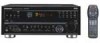
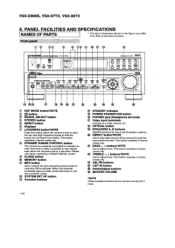
...POWER STANDBY/ON button ® PHONES jack (Headphone terminal) © Video input terminals Connect to a video camera, etc. ® OPTICAL button ® SPEAKERS A, B buttons ON/OFF switches for the A and B speaker systems. ® DIRECT button'NOTE Use to switch the auto stereo/monaural mode for receiving FM broadcasts. This button operates in stereo mode only. ® TREBLE -, + buttons NOTE Use to adjust tone. This button operates in stereo mode only. ® BASS - , + buttons NOTE Use to adjust tone. VSX-D906S, VSX-07TX, VSX-09TX 8. Qe DYNAMIC RANGE CONTROL button The volume...
...POWER STANDBY/ON button ® PHONES jack (Headphone terminal) © Video input terminals Connect to a video camera, etc. ® OPTICAL button ® SPEAKERS A, B buttons ON/OFF switches for the A and B speaker systems. ® DIRECT button'NOTE Use to switch the auto stereo/monaural mode for receiving FM broadcasts. This button operates in stereo mode only. ® TREBLE -, + buttons NOTE Use to adjust tone. This button operates in stereo mode only. ® BASS - , + buttons NOTE Use to adjust tone. VSX-D906S, VSX-07TX, VSX-09TX 8. Qe DYNAMIC RANGE CONTROL button The volume...
Service Manual
Page 80
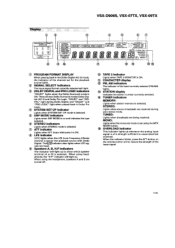
... PROGRAM FORMAT DISPLAY When playing back in Dolby Pro Logic. There are two Dolby Surround modes-Do)by Surround mode is ON. "DOLBY" and "DIG ITAL" light during auto stereo mode. TUNED: Lights when broadcasts are input. MONO: Lights when the monaural mode is set for the playback source with Dolby Digital. Os SYSTEM SET UP indicator Lights when SYSTEM SET UP mode is of the channel set using the MPX MODE button. ® OVERLOAD Indicator This indicator lights up whenever the analog input signal is selected...
... PROGRAM FORMAT DISPLAY When playing back in Dolby Pro Logic. There are two Dolby Surround modes-Do)by Surround mode is ON. "DOLBY" and "DIG ITAL" light during auto stereo mode. TUNED: Lights when broadcasts are input. MONO: Lights when the monaural mode is set for the playback source with Dolby Digital. Os SYSTEM SET UP indicator Lights when SYSTEM SET UP mode is of the channel set using the MPX MODE button. ® OVERLOAD Indicator This indicator lights up whenever the analog input signal is selected...
Service Manual
Page 81
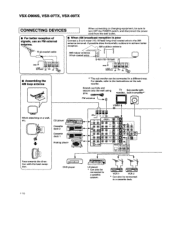
.... DVD player LD player " Can also be connected in amplifier"' FM antenna ® VIDEO IN When attaching on the sub woofer. Ce -'8 Qpu Qp. e CANAAN(( p NCOPBI QeQe ~QeQo -.Oe:O C6) k~ CO oN IN I u e T N VIDEO ZR ' O Qp. O~ C O~ VOR cz z z z o VOR VCR 1 VCR 2 " Can also be sure to turn OFF the POWER switch, and disconnect the power cord from ths wall outlet. ~ For better reception of signals, use an...
.... DVD player LD player " Can also be connected in amplifier"' FM antenna ® VIDEO IN When attaching on the sub woofer. Ce -'8 Qpu Qp. e CANAAN(( p NCOPBI QeQe ~QeQo -.Oe:O C6) k~ CO oN IN I u e T N VIDEO ZR ' O Qp. O~ C O~ VOR cz z z z o VOR VCR 1 VCR 2 " Can also be sure to turn OFF the POWER switch, and disconnect the power cord from ths wall outlet. ~ For better reception of signals, use an...
Service Manual
Page 82
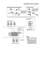
... figures may differ from speakers connected to ON . 111 Be sure to VIDEO. R, and yellow plug to L insert completely. VSX-D906S, YSX-07TX, VSX-09TX ~ AIRantenna terminal ~ Inputloutput plugs ~ Speaker terminals (3/S Ln I 0 OO W CHED OKH OHUK Video equipment such as a video camera, etc. Please reger to the plug's manual for the speaker system. ~ Sound is output from those on the front panel is set the SPEAKERS B button to FR, FL...
... figures may differ from speakers connected to ON . 111 Be sure to VIDEO. R, and yellow plug to L insert completely. VSX-D906S, YSX-07TX, VSX-09TX ~ AIRantenna terminal ~ Inputloutput plugs ~ Speaker terminals (3/S Ln I 0 OO W CHED OKH OHUK Video equipment such as a video camera, etc. Please reger to the plug's manual for the speaker system. ~ Sound is output from those on the front panel is set the SPEAKERS B button to FR, FL...
Service Manual
Page 83
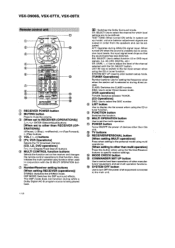
... broadcast channel. SELECT: Use to select the channel for setting the frequency value when the station call is unstable due to exces sive input levels, the input signal level drops so that function. LIST IN: Use to sw itch to other than RECEIVER (OP ERATIONS)] tuner function. 06 FUNCTION button Switches the function. CLASS: Switches the CLASS number. The DSP mode does not function during ANALOG signal input. VSX-D906S, VSX-07TX, VSX-09TX QD : Switches the Dolby Surround mode. Qo MULTI OPERATION button Use to set to the list input screen w hen...
... broadcast channel. SELECT: Use to select the channel for setting the frequency value when the station call is unstable due to exces sive input levels, the input signal level drops so that function. LIST IN: Use to sw itch to other than RECEIVER (OP ERATIONS)] tuner function. 06 FUNCTION button Switches the function. CLASS: Switches the CLASS number. The DSP mode does not function during ANALOG signal input. VSX-D906S, VSX-07TX, VSX-09TX QD : Switches the Dolby Surround mode. Qo MULTI OPERATION button Use to set to the list input screen w hen...
Service Manual
Page 84
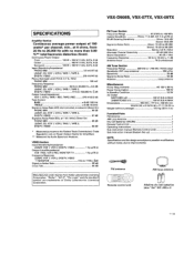
... . Sub instruction manual (Remote Control Unit) ... Sub instruction manual [System Set up NOTE: Specificetl ons and the design are trademarks of 100 watts" per channel, min., at 6 ohms, from Do/by Au dio Spectrum A na/yzer. Continuous Power Output Front 100 W + 100 W (1 kHz, 0.8 %, 6 Q) Center . 1 00 W (1 kHz, 0.8 %, 6 n l Surround 100 W + 100 W (1 kHz, 0.8 %, 6 tt) Input (Sensitivity/Impedance) PHONO M M 3.8 mV/47 kQ LD/SAT, CD, VCR 1, VCR 2, TAPE 1, TAPE 2, DVD/TV, VIDEO . . 275 mV/47 kD Phono Overload Level...
... . Sub instruction manual (Remote Control Unit) ... Sub instruction manual [System Set up NOTE: Specificetl ons and the design are trademarks of 100 watts" per channel, min., at 6 ohms, from Do/by Au dio Spectrum A na/yzer. Continuous Power Output Front 100 W + 100 W (1 kHz, 0.8 %, 6 Q) Center . 1 00 W (1 kHz, 0.8 %, 6 n l Surround 100 W + 100 W (1 kHz, 0.8 %, 6 tt) Input (Sensitivity/Impedance) PHONO M M 3.8 mV/47 kQ LD/SAT, CD, VCR 1, VCR 2, TAPE 1, TAPE 2, DVD/TV, VIDEO . . 275 mV/47 kD Phono Overload Level...


