Operating Instructions
Page 5
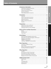
SET UP Table of Contents Introductory Information 6 Checking the Supplied Accessories 6 How to Use This Manual 6 Preparing the Remote Control 6 Receiver Installation 7 When Making Cable Connections 7 Connections 8 Antennas ...8 Audio Components Connections 9 Video Components Connections 10 Digital Connections ...Selecting a Sound Mode 31 CINEMA Re-EQ playback 33 Listening in MIDNIGHT Listening Mode 35 Tuner Operations 36 Automatic and Manual Tuning 36 Direct Tuning 37 Memorizing Frequently Tuned Stations 38 Recalling the Memorized Stations 39 Other Operations 40 Playback ...40...
SET UP Table of Contents Introductory Information 6 Checking the Supplied Accessories 6 How to Use This Manual 6 Preparing the Remote Control 6 Receiver Installation 7 When Making Cable Connections 7 Connections 8 Antennas ...8 Audio Components Connections 9 Video Components Connections 10 Digital Connections ...Selecting a Sound Mode 31 CINEMA Re-EQ playback 33 Listening in MIDNIGHT Listening Mode 35 Tuner Operations 36 Automatic and Manual Tuning 36 Direct Tuning 37 Memorizing Frequently Tuned Stations 38 Recalling the Memorized Stations 39 Other Operations 40 Playback ...40...
Operating Instructions
Page 6
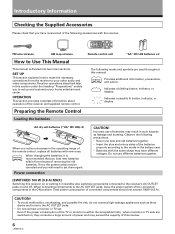
...Indicates a steadily lit button, indicator, or display. Power connection CAUTION! FM wire antenna AM loop antenna How to Use This Manual This manual is within five minutes of the connected components in the battery case. • Batteries with the same shape may result in...that you have different voltages. OPERATION This section provides complete information about operation of connected components should not exceed 100W (0.8 A) . Receiver operations described later in such hazards as blow dryers and irons to set up and customize your other audio and video components. ...
...Indicates a steadily lit button, indicator, or display. Power connection CAUTION! FM wire antenna AM loop antenna How to Use This Manual This manual is within five minutes of the connected components in the battery case. • Batteries with the same shape may result in...that you have different voltages. OPERATION This section provides complete information about operation of connected components should not exceed 100W (0.8 A) . Receiver operations described later in such hazards as blow dryers and irons to set up and customize your other audio and video components. ...
Operating Instructions
Page 9
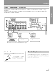
...187; OUTPUT L R FRONT PREOUT L R FRONT SPEAKERS R L CENTER PREOUT L SORROUND PREOUT R SUBWOOFER PREOUT CENTER SPEAKER R L SURROUND SPEAKERS A B CAUTION: SEE INSTRUCTION MANUAL ATTENTION: SEE INSTRUCTION MANUAL 6~LESS THAN 8Ω /SPEAKER 6~MOINS DE 8Ω /HAUTPARLEUR 8~16Ω / SPEAKER 8~16Ω / SPEAKER IMPEDANCE SELECTOR » « PLAY REC L L..."Digital Connections" on where the cassette deck is caused by leakage flux from the transformer in the receiver. SET UP Connections Audio Components Connections Be sure to switch power to standby and remove the power ...
...187; OUTPUT L R FRONT PREOUT L R FRONT SPEAKERS R L CENTER PREOUT L SORROUND PREOUT R SUBWOOFER PREOUT CENTER SPEAKER R L SURROUND SPEAKERS A B CAUTION: SEE INSTRUCTION MANUAL ATTENTION: SEE INSTRUCTION MANUAL 6~LESS THAN 8Ω /SPEAKER 6~MOINS DE 8Ω /HAUTPARLEUR 8~16Ω / SPEAKER 8~16Ω / SPEAKER IMPEDANCE SELECTOR » « PLAY REC L L..."Digital Connections" on where the cassette deck is caused by leakage flux from the transformer in the receiver. SET UP Connections Audio Components Connections Be sure to switch power to standby and remove the power ...

Operating Instructions
Page 10
...Digital Connections" on the rear panel, S, S1 and S2 S-video connection can make connections to this unit is possible by connecting the receiver to your TV monitor or video camera via the S-Video jack. TV monitor INPUT VIDEO S-VIDEO » Video deck (1) «... L R FRONT SPEAKERS R L CENTER PREOUT L SORROUND PREOUT R SUBWOOFER PREOUT CENTER SPEAKER R L SURROUND SPEAKERS A B CAUTION: SEE INSTRUCTION MANUAL ATTENTION: SEE INSTRUCTION MANUAL 6~LESS THAN 8Ω /SPEAKER 6~MOINS DE 8Ω /HAUTPARLEUR 8~16Ω / SPEAKER 8~16Ω / SPEAKER IMPEDANCE SELECTOR AC OUTLET...
...Digital Connections" on the rear panel, S, S1 and S2 S-video connection can make connections to this unit is possible by connecting the receiver to your TV monitor or video camera via the S-Video jack. TV monitor INPUT VIDEO S-VIDEO » Video deck (1) «... L R FRONT SPEAKERS R L CENTER PREOUT L SORROUND PREOUT R SUBWOOFER PREOUT CENTER SPEAKER R L SURROUND SPEAKERS A B CAUTION: SEE INSTRUCTION MANUAL ATTENTION: SEE INSTRUCTION MANUAL 6~LESS THAN 8Ω /SPEAKER 6~MOINS DE 8Ω /HAUTPARLEUR 8~16Ω / SPEAKER 8~16Ω / SPEAKER IMPEDANCE SELECTOR AC OUTLET...
Operating Instructions
Page 11
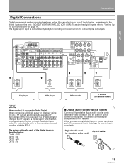
... signal which is output directly to four of the digital inputs is required. The factory setting for Surround Sound" on this receiver. ANTENNA DIGITAL IN OPT 1 PCM/ /DTS FM UNBAL 75Ω OPT 2 DVD 5.1 CH INPUT OPT 3 SURROUND ... FRONT PREOUT L R FRONT SPEAKERS R L CENTER PREOUT L SORROUND PREOUT R SUBWOOFER PREOUT CENTER SPEAKER R L SURROUND SPEAKERS A B CAUTION: SEE INSTRUCTION MANUAL ATTENTION: SEE INSTRUCTION MANUAL 6~LESS THAN 8Ω /SPEAKER 6~MOINS DE 8Ω /HAUTPARLEUR 8~16Ω / SPEAKER 8~16Ω / SPEAKER IMPEDANCE SELECTOR » »...
... signal which is output directly to four of the digital inputs is required. The factory setting for Surround Sound" on this receiver. ANTENNA DIGITAL IN OPT 1 PCM/ /DTS FM UNBAL 75Ω OPT 2 DVD 5.1 CH INPUT OPT 3 SURROUND ... FRONT PREOUT L R FRONT SPEAKERS R L CENTER PREOUT L SORROUND PREOUT R SUBWOOFER PREOUT CENTER SPEAKER R L SURROUND SPEAKERS A B CAUTION: SEE INSTRUCTION MANUAL ATTENTION: SEE INSTRUCTION MANUAL 6~LESS THAN 8Ω /SPEAKER 6~MOINS DE 8Ω /HAUTPARLEUR 8~16Ω / SPEAKER 8~16Ω / SPEAKER IMPEDANCE SELECTOR » »...
Operating Instructions
Page 29
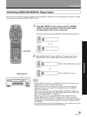
...one of the component set in "ANALOG", digital noise is set to the instruction manual supplied with your DVD player. 29 With digital signal formats other than these, set SIGNAL SELECT to "ANALOG". • This receiver can be switched to the source component. SIGNAL SELECT ANALOG SIGNAL SELECT ANALOG SP...When an LD or CD player compatible with DTS is played back with SIGNAL SELECT set in the digital input setting (Refer to page 20, 21) can only play back Dolby Digital, PCM (32kHz, 44kHz, and 48kHz), DTS digital signal formats. Each press switches between ANALOG and DIGITAL ...
...one of the component set in "ANALOG", digital noise is set to the instruction manual supplied with your DVD player. 29 With digital signal formats other than these, set SIGNAL SELECT to "ANALOG". • This receiver can be switched to the source component. SIGNAL SELECT ANALOG SIGNAL SELECT ANALOG SP...When an LD or CD player compatible with DTS is played back with SIGNAL SELECT set in the digital input setting (Refer to page 20, 21) can only play back Dolby Digital, PCM (32kHz, 44kHz, and 48kHz), DTS digital signal formats. Each press switches between ANALOG and DIGITAL ...
Operating Instructions
Page 30
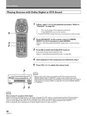
...CONTROL UNIT (Refer to "Switching the Dolby/DTS mode" on . To prevent noise, you need to make digital connections (Refer to pages 20, 21) and set in Dolby Digital When connecting a DVD/LD player or LD player using the AC-3 RF output, a commercially available RF demodulator (RFD...-1) is required. Refer to the instruction manual supplied with the RFD-1. FQ 5 VOL VOL CHANNEL 1 Turn on the power of the playback component. 2 Press RECEIVER to turn on page 40.) - The RF demodulator changes the RF signal to a digital ...
...CONTROL UNIT (Refer to "Switching the Dolby/DTS mode" on . To prevent noise, you need to make digital connections (Refer to pages 20, 21) and set in Dolby Digital When connecting a DVD/LD player or LD player using the AC-3 RF output, a commercially available RF demodulator (RFD...-1) is required. Refer to the instruction manual supplied with the RFD-1. FQ 5 VOL VOL CHANNEL 1 Turn on the power of the playback component. 2 Press RECEIVER to turn on page 40.) - The RF demodulator changes the RF signal to a digital ...

Operating Instructions
Page 36
Tuner Operations Automatic and Manual Tuning The following steps show you want, see "Direct Tuning" on the following page. 3 RECEIVER TV MUTING FQ TV FUNC + ENTER - Each press switches the band: FM j AM...not light when tuning an FM station, because the station is too far away or the broadcast signal is received automatically. 4 SIGNAL SELECT ANALOG SP A dB 1 2 Press ENTER on the remote or FM/AM on...or AM). FQ VOL VOL CHANNEL MULTI CONTROL DVD/LD TV/SAT CD VCR 1 TVCONTROL TUNER VCR 2 RECEIVER MD/TAPE DSP MODE MIDNIGHT 12 34 CH.SELECT TEST TONE ATT SIG.SELECT 56 7 8 CN.LEVEL ...
Tuner Operations Automatic and Manual Tuning The following steps show you want, see "Direct Tuning" on the following page. 3 RECEIVER TV MUTING FQ TV FUNC + ENTER - Each press switches the band: FM j AM...not light when tuning an FM station, because the station is too far away or the broadcast signal is received automatically. 4 SIGNAL SELECT ANALOG SP A dB 1 2 Press ENTER on the remote or FM/AM on...or AM). FQ VOL VOL CHANNEL MULTI CONTROL DVD/LD TV/SAT CD VCR 1 TVCONTROL TUNER VCR 2 RECEIVER MD/TAPE DSP MODE MIDNIGHT 12 34 CH.SELECT TEST TONE ATT SIG.SELECT 56 7 8 CN.LEVEL ...
Operating Instructions
Page 38
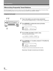
Using the front panel 32 4 1 Tune in the station you how to memorize up to 30 stations. 38 See "Automatic and Manual Tuning" or "Direct Tuning" on pages 36, 37. 2 Press MEMORY to select a class. SIGNAL SELECT ANALOG SP A dB The station is ...memorized automatically after 5 seconds. "A--" blinks in 3 classes (each holding 10 channels). When memorizing FM frequencies, the receiver also memorizes the MPX mode (STEREO or MONO). SIGNAL SELECT ANALOG SP A dB 3 Press CLASS repeatedly to activate the memory function. Repeat steps 1 through...
Using the front panel 32 4 1 Tune in the station you how to memorize up to 30 stations. 38 See "Automatic and Manual Tuning" or "Direct Tuning" on pages 36, 37. 2 Press MEMORY to select a class. SIGNAL SELECT ANALOG SP A dB The station is ...memorized automatically after 5 seconds. "A--" blinks in 3 classes (each holding 10 channels). When memorizing FM frequencies, the receiver also memorizes the MPX mode (STEREO or MONO). SIGNAL SELECT ANALOG SP A dB 3 Press CLASS repeatedly to activate the memory function. Repeat steps 1 through...
Operating Instructions
Page 55
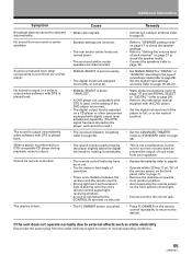
...11) and set SIGNAL SELECT to "DIGITAL" (refer to page 29). • Refer to the instruction manual supplied with the DVD player. • Set the digital volume level of connections made (refer to page... 29). • Set the digital input settings correctly (refer to page 16, 20, 21). If the unit does not operate normally due to external effects such as fluorescent light is shining... are turned down to prevent the output of operation. • There is an obstacle between the receiver and the remote control. • Strong light such as static electricity Disconnect the power plug from...
...11) and set SIGNAL SELECT to "DIGITAL" (refer to page 29). • Refer to the instruction manual supplied with the DVD player. • Set the digital volume level of connections made (refer to page... 29). • Set the digital input settings correctly (refer to page 16, 20, 21). If the unit does not operate normally due to external effects such as fluorescent light is shining... are turned down to prevent the output of operation. • There is an obstacle between the receiver and the remote control. • Strong light such as static electricity Disconnect the power plug from...


