Owner's Manual
Page 4
...224; la clientèle de Pioneer: Pioneer Électroniques du Canada, Inc. S018_A_EF iivi EN Safety Precautions Product Name: Plasma Display Model Number: PRO-1010HD / PRO-810HD Product Category: Class B Personal Computers & Peripherals Responsible Party Name: PIONEER ELECTRONICS [USA] INC. Service &#... COMMISSION DECLARATION OF CONFORMITY This device complies with part 15 of Canada, Inc. Operation is subject to purchase replacement parts, operating instructions, service manuals, or accessories, please call the number shown below. 8 0 0 - 4 2 1 - 1 4 0 4 Please do not ship...
...224; la clientèle de Pioneer: Pioneer Électroniques du Canada, Inc. S018_A_EF iivi EN Safety Precautions Product Name: Plasma Display Model Number: PRO-1010HD / PRO-810HD Product Category: Class B Personal Computers & Peripherals Responsible Party Name: PIONEER ELECTRONICS [USA] INC. Service &#... COMMISSION DECLARATION OF CONFORMITY This device complies with part 15 of Canada, Inc. Operation is subject to purchase replacement parts, operating instructions, service manuals, or accessories, please call the number shown below. 8 0 0 - 4 2 1 - 1 4 0 4 Please do not ship...

Owner's Manual
Page 5
... PHASE (Automatic Adjust 39 Adjusting Screen POSITION, CLOCK, and PHASE (Manual Adjust 39 Other Operations 42 Setting the PURECINEMA Mode 42 Setting Screen Center Brightness Compensation (BRT. PIONEER cannot assume liabilities for purchasing this Unit 11 Connection to INPUT1 (D-sub... 33 Picture and Screen Adjustment ......... 35 Picture Adjustment (1 35 Picture Adjustment (2 36 Picture Adjustment (3 37 Returning to Use This Manual 2 Checking Supplied Accessories 4 Part Names and Functions 5 Main Unit 5 Remote Control Unit 6 Connection Panel 8 Installation and Connections...
... PHASE (Automatic Adjust 39 Adjusting Screen POSITION, CLOCK, and PHASE (Manual Adjust 39 Other Operations 42 Setting the PURECINEMA Mode 42 Setting Screen Center Brightness Compensation (BRT. PIONEER cannot assume liabilities for purchasing this Unit 11 Connection to INPUT1 (D-sub... 33 Picture and Screen Adjustment ......... 35 Picture Adjustment (1 35 Picture Adjustment (2 36 Picture Adjustment (3 37 Returning to Use This Manual 2 Checking Supplied Accessories 4 Part Names and Functions 5 Main Unit 5 Remote Control Unit 6 Connection Panel 8 Installation and Connections...
Owner's Manual
Page 6
... EXIT Please note that would seem most logical for both the PRO-1010HD and PRO-810HD. Power Management and Sun Microsystems are those for correct operation of Microsoft Corporation. FontAvenue is a registered trademark of the plasma display with selecting a source component up this manual are registered trademarks of NEC Corporation. The remainder of the...
... EXIT Please note that would seem most logical for both the PRO-1010HD and PRO-810HD. Power Management and Sun Microsystems are those for correct operation of Microsoft Corporation. FontAvenue is a registered trademark of the plasma display with selecting a source component up this manual are registered trademarks of NEC Corporation. The remainder of the...
Owner's Manual
Page 7
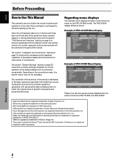
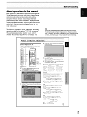
English About operations in this manual Each operation is described in its contents, the input source and various other control settings. some difference will refer to the operating controls found on ...
English About operations in this manual Each operation is described in its contents, the input source and various other control settings. some difference will refer to the operating controls found on ...
Owner's Manual
Page 14
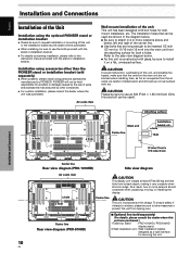
...sure to use the bolts provided with the stand or installation bracket. ÷ For details concerning installation, please refer to the instruction manual provided with the stand or installation bracket. Air vents (fan) Wall-mount installation of the unit This unit has been designed with ... Rear view diagram (PRO-810HD) CAUTION This display unit weighs at least 67 lbs (30 kg) and has little front-to prevent the unit from tipping over. 7 Optional line (sold separately) ÷ When possible, please install using parts and accessories manufactured by PIONEER. PIONEER will not be held...
...sure to use the bolts provided with the stand or installation bracket. ÷ For details concerning installation, please refer to the instruction manual provided with the stand or installation bracket. Air vents (fan) Wall-mount installation of the unit This unit has been designed with ... Rear view diagram (PRO-810HD) CAUTION This display unit weighs at least 67 lbs (30 kg) and has little front-to prevent the unit from tipping over. 7 Optional line (sold separately) ÷ When possible, please install using parts and accessories manufactured by PIONEER. PIONEER will not be held...

Owner's Manual
Page 18
.... Please see pages 23 to 25. On-screen setup is necessary after connection. Secure by tightening the terminal screws on top of your PC's instruction manual or consult the maker or nearest dealer of the green signal. Note When making G ON SYNC connections, do not make any connections to ANALOG RGB...
.... Please see pages 23 to 25. On-screen setup is necessary after connection. Secure by tightening the terminal screws on top of your PC's instruction manual or consult the maker or nearest dealer of the green signal. Note When making G ON SYNC connections, do not make any connections to ANALOG RGB...

Owner's Manual
Page 21
...) (HDMI) Installation and Connections 17 EN English Installation and Connections About DTV Set Top Box Connection To ensure proper connection, please carefully read the instruction manual supplied with are as follows.
...) (HDMI) Installation and Connections 17 EN English Installation and Connections About DTV Set Top Box Connection To ensure proper connection, please carefully read the instruction manual supplied with are as follows.
Owner's Manual
Page 23
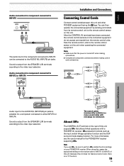
...such as the input switch linkage operation function and the DSP surround mode display function. About SR+ The CONTROL OUT terminal on your PIONEER AV receiver. Sound is turned off when making connections. ÷ Complete all component connections before making control cord connections. For more... information, see the user's manual for component connected to perform SR+ related function settings on the rear of this unit (because this unit and other PIONEER equipment having the Î logo. Audio connection for the PIONEER AV receiver supporting SR+. Note If you use...
...such as the input switch linkage operation function and the DSP surround mode display function. About SR+ The CONTROL OUT terminal on your PIONEER AV receiver. Sound is turned off when making connections. ÷ Complete all component connections before making control cord connections. For more... information, see the user's manual for component connected to perform SR+ related function settings on the rear of this unit (because this unit and other PIONEER equipment having the Î logo. Audio connection for the PIONEER AV receiver supporting SR+. Note If you use...
Owner's Manual
Page 27
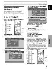
... procedure described below and make settings as follows: 3 D-SUB 2 3 HDMI 2 5 Press the SET button. Adjustment for other signal frequency formats is performed automatically, so no manual setting is required (Setting [SIGNAL FORMAT] is not possible). ÷ The [COLOR DECODING] setting is not supported when inputting a computer signal, or when the [SIGNAL...
... procedure described below and make settings as follows: 3 D-SUB 2 3 HDMI 2 5 Press the SET button. Adjustment for other signal frequency formats is performed automatically, so no manual setting is required (Setting [SIGNAL FORMAT] is not possible). ÷ The [COLOR DECODING] setting is not supported when inputting a computer signal, or when the [SIGNAL...
Owner's Manual
Page 28
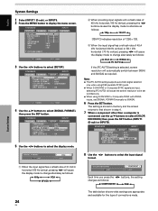
... returns to that shown in step 4. 7 When a component other than a computer is selected, screen resolution will cause the screen resolution to be set [SIGNAL FORMAT] manually to select [COLOR DECODING] then press the SET button (INPUT1 (D-sub) or INPUT5). System Settings English System Settings 1 Select INPUT1 (D-sub), or INPUT5. 2 Press the...
... returns to that shown in step 4. 7 When a component other than a computer is selected, screen resolution will cause the screen resolution to be set [SIGNAL FORMAT] manually to select [COLOR DECODING] then press the SET button (INPUT1 (D-sub) or INPUT5). System Settings English System Settings 1 Select INPUT1 (D-sub), or INPUT5. 2 Press the...
Owner's Manual
Page 29
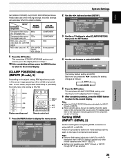
... [AUTO]. This completes [CLAMP POSITION] setting, and returns you are selected. ENHANCE : OFF : AUTO : 480p : RGB : ON OPTION 3 Use the 5/∞ buttons to the instruction manual supplied with [INPUT1 SELECT]. ÷ Setting is [AUTO].
... [AUTO]. This completes [CLAMP POSITION] setting, and returns you are selected. ENHANCE : OFF : AUTO : 480p : RGB : ON OPTION 3 Use the 5/∞ buttons to the instruction manual supplied with [INPUT1 SELECT]. ÷ Setting is [AUTO].

Owner's Manual
Page 30
... : HDMI INPUT BRT. The unit has been factory set at the AUTO setting. In this event, select COLOR1, COLOR2, COLOR3 or COLOR4 manually in step 3. 7 After completing settings, press the MENU button to return to the display shown in accordance with some input signals. PICTURE SELECT... signals. COLOR4: Select COLOR4 to select [HDMI INPUT], then press the SET button. Each time you to switch the input signal format to automatic or manual when inputting the digital signal. 1 Press the MENU button to select [SET UP]. S TA N D A R D PICTURE SCREEN SETUP CONTRAST BRIGHTNESS ...
... : HDMI INPUT BRT. The unit has been factory set at the AUTO setting. In this event, select COLOR1, COLOR2, COLOR3 or COLOR4 manually in step 3. 7 After completing settings, press the MENU button to return to the display shown in accordance with some input signals. PICTURE SELECT... signals. COLOR4: Select COLOR4 to select [HDMI INPUT], then press the SET button. Each time you to switch the input signal format to automatic or manual when inputting the digital signal. 1 Press the MENU button to select [SET UP]. S TA N D A R D PICTURE SCREEN SETUP CONTRAST BRIGHTNESS ...

Owner's Manual
Page 31
...signals. The unit has been factory set at the AUTO setting. English AUDIO This function allows you to switch the audio signal to automatic or manual when inputting the digital signal. 1 Press the MENU button to display the menu screen. Note Even when AUTO is required when using the ...CONTROL OUT jack on the rear of this event, select DIGITAL or ANALOG manually in step 3. 7 After completing settings, press the MENU button to return to the normal display. In this unit to connect another Pioneer product (Refer to page 19 for connection details). 1 Press the MENU button to...
...signals. The unit has been factory set at the AUTO setting. English AUDIO This function allows you to switch the audio signal to automatic or manual when inputting the digital signal. 1 Press the MENU button to display the menu screen. Note Even when AUTO is required when using the ...CONTROL OUT jack on the rear of this event, select DIGITAL or ANALOG manually in step 3. 7 After completing settings, press the MENU button to return to the normal display. In this unit to connect another Pioneer product (Refer to page 19 for connection details). 1 Press the MENU button to...

Owner's Manual
Page 41
... (3) You can save picture adjustment values for each INPUT and each AV SELECTION mode. LOW, G. HIGH, R. HIGH, B. MANUAL/** is not possible when in the DYNAMIC mode in COLOR TEMP. Provides standard brightness γ characteristics. ¶ GAMMA2.2 ... ... ** section as follows: 3 GAMMA1.8 2 3 GAMMA2.0 2 3 GAMMA2.2 2 Picture and Screen Adjustment ¶ GAMMA1.8 ... 3 LOW 2 3 MID LOW 2 3 MID 2 3 MANUAL/**2 3 HIGH 2 3 MID HIGH 2 ¶ LOW ......... Provides yellowish color tone with low warmth. ¶ MID-LOW ... HIGH ... LOW ... MENU 5/∞ 2/3 SET MENU ...
... (3) You can save picture adjustment values for each INPUT and each AV SELECTION mode. LOW, G. HIGH, R. HIGH, B. MANUAL/** is not possible when in the DYNAMIC mode in COLOR TEMP. Provides standard brightness γ characteristics. ¶ GAMMA2.2 ... ... ** section as follows: 3 GAMMA1.8 2 3 GAMMA2.0 2 3 GAMMA2.2 2 Picture and Screen Adjustment ¶ GAMMA1.8 ... 3 LOW 2 3 MID LOW 2 3 MID 2 3 MANUAL/**2 3 HIGH 2 3 MID HIGH 2 ¶ LOW ......... Provides yellowish color tone with low warmth. ¶ MID-LOW ... HIGH ... LOW ... MENU 5/∞ 2/3 SET MENU ...
Owner's Manual
Page 43
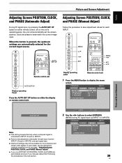
...signals. When the button is connected to INPUT1 (D-sub) or INPUT5. ÷ Perform this page, "Adjusting Screen POSITION, CLOCK, and PHASE (Manual Adjust)". ÷ If you manually adjust them following the procedures in the next section. S TA N D A R D PICTURE SCREEN CONTRAST : BRIGHTNESS : H. SET ENTER MENU... be possible for each input function (INPUT1 (D-sub) or INPUT5), and each INPUT. AUTO SET UP Adjusting Screen POSITION, CLOCK, and PHASE (Manual Adjust) Follow the procedure to select [SCREEN]. (MENU during PC signal input via INPUT1 or INPUT5.) S TA N D A R D PICTURE...
...signals. When the button is connected to INPUT1 (D-sub) or INPUT5. ÷ Perform this page, "Adjusting Screen POSITION, CLOCK, and PHASE (Manual Adjust)". ÷ If you manually adjust them following the procedures in the next section. S TA N D A R D PICTURE SCREEN CONTRAST : BRIGHTNESS : H. SET ENTER MENU... be possible for each input function (INPUT1 (D-sub) or INPUT5), and each INPUT. AUTO SET UP Adjusting Screen POSITION, CLOCK, and PHASE (Manual Adjust) Follow the procedure to select [SCREEN]. (MENU during PC signal input via INPUT1 or INPUT5.) S TA N D A R D PICTURE...


