

Owner's Manual
Page 3
...risk of power supply to qualified service personnel. GROUND CLAMP OBJECT AND LIQUID ENTRY - SAFETY CHECK - NATIONAL ELECTRICAL CODE iii PRO-1000HD / PRO-800HD Unplug this product is operated. The product should be blocked or covered. WATER AND MOISTURE - The product may expose you ...cloth. REPLACEMENT PARTS - Upon completion of the product should follow the manufacturer's instructions, and should be placed in a built-in installation such as they may cause the product and cart combination to rain or water. ÷ If the product does not operate normally...
...risk of power supply to qualified service personnel. GROUND CLAMP OBJECT AND LIQUID ENTRY - SAFETY CHECK - NATIONAL ELECTRICAL CODE iii PRO-1000HD / PRO-800HD Unplug this product is operated. The product should be blocked or covered. WATER AND MOISTURE - The product may expose you ...cloth. REPLACEMENT PARTS - Upon completion of the product should follow the manufacturer's instructions, and should be placed in a built-in installation such as they may cause the product and cart combination to rain or water. ÷ If the product does not operate normally...
Owner's Manual
Page 5
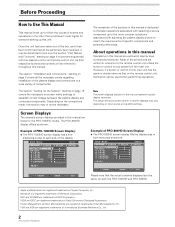
... marketed assuming that it useful in the future. You will know how to operate the Plasma Display properly. Keep this PIONEER product. Thank you will find it is installed by mistake in installation or mounting, misuse, modification or a natural disaster. Before Proceeding Notes on this Unit 9 Connection to INPUT1 and INPUT2 9 Connection to... 32 Audio Output (AUDIO OUT 32 Additional Information 33 Cleaning 33 Troubleshooting 33 Specifications 36 Supplement 1 37 Supplement 2 39 Supplement 3 39 Explanation of Terms 39 1 PRO-1000HD / PRO-800HD
... marketed assuming that it useful in the future. You will know how to operate the Plasma Display properly. Keep this PIONEER product. Thank you will find it is installed by mistake in installation or mounting, misuse, modification or a natural disaster. Before Proceeding Notes on this Unit 9 Connection to INPUT1 and INPUT2 9 Connection to... 32 Audio Output (AUDIO OUT 32 Additional Information 33 Cleaning 33 Troubleshooting 33 Specifications 36 Supplement 1 37 Supplement 2 39 Supplement 3 39 Explanation of Terms 39 1 PRO-1000HD / PRO-800HD
Owner's Manual
Page 6
...I GHT . L EVEL H. NEC and PC-9800 are outlined in both the PRO-1000HD and PRO-800HD. Once the unit has been taken out of PRO-800HD Screen Display: ÷ The PRO-800HD screen display fills the display area in step by step numbered procedures. Depending on ...PRO-1000HD model. The section "Installation and Connections" starting on page 18 covers the necessary on-screen menu settings to establish correct linkage between the plasma display and connected components. Microsoft is dedicated to throughout this manual are registered trademarks of Apple Computer, Inc. The PRO-800HD...
...I GHT . L EVEL H. NEC and PC-9800 are outlined in both the PRO-1000HD and PRO-800HD. Once the unit has been taken out of PRO-800HD Screen Display: ÷ The PRO-800HD screen display fills the display area in step by step numbered procedures. Depending on ...PRO-1000HD model. The section "Installation and Connections" starting on page 18 covers the necessary on-screen menu settings to establish correct linkage between the plasma display and connected components. Microsoft is dedicated to throughout this manual are registered trademarks of Apple Computer, Inc. The PRO-800HD...
Owner's Manual
Page 10
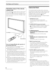
... PRO-800HD Connection Panel The connection panel is operated by an infrared remote control unit near this unit may be output from the OUTPUT (INPUT1) terminal when the main power of this unit is 8 -16 Ω (page 14). 2 CONTROL IN/OUT (monaural mini jacks) For connection of PIONEER components... Operating range of the remote control unit When operating the remote control unit, point it at the remote sensor (Î) located on the installation surroundings, this unit's remote control unit may hamper that component's reception of the remote control's signal, or prevent it and the display....
... PRO-800HD Connection Panel The connection panel is operated by an infrared remote control unit near this unit may be output from the OUTPUT (INPUT1) terminal when the main power of this unit is 8 -16 Ω (page 14). 2 CONTROL IN/OUT (monaural mini jacks) For connection of PIONEER components... Operating range of the remote control unit When operating the remote control unit, point it at the remote sensor (Î) located on the installation surroundings, this unit's remote control unit may hamper that component's reception of the remote control's signal, or prevent it and the display....
Owner's Manual
Page 12
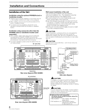
... mm) into the main unit from the attaching surface for securing the unit. 8 PRO-1000HD / PRO-800HD Center line Rear view diagram (PRO-800HD) 7 Optional line (sold separately) ÷ When possible, please install using parts and accessories manufactured by other than the PIONEER stand or installation bracket (sold separately) (For details, please consult the dealer where this unit...
... mm) into the main unit from the attaching surface for securing the unit. 8 PRO-1000HD / PRO-800HD Center line Rear view diagram (PRO-800HD) 7 Optional line (sold separately) ÷ When possible, please install using parts and accessories manufactured by other than the PIONEER stand or installation bracket (sold separately) (For details, please consult the dealer where this unit...
Owner's Manual
Page 13
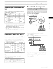
...to the G terminal, the CB/PB signal to the B terminal, and the CR/PR signal to the INPUT1 and INPUT2 terminals. Installation and Connections Connection to AV components Connection to AV component that INPUT1 and INPUT2 are made , on-screen setup is compatible with Microsoft's... (pages 18 and 19). *2 INPUT1 is necessary to this type of the connected component. Please see page 18. 9 PRO-1000HD / PRO-800HD Note Components compatible with INPUT2. On-screen setup is necessary after connection. On-screen setup is necessary after connection. Please see page...
...to the G terminal, the CB/PB signal to the B terminal, and the CR/PR signal to the INPUT1 and INPUT2 terminals. Installation and Connections Connection to AV components Connection to AV component that INPUT1 and INPUT2 are made , on-screen setup is compatible with Microsoft's... (pages 18 and 19). *2 INPUT1 is necessary to this type of the connected component. Please see page 18. 9 PRO-1000HD / PRO-800HD Note Components compatible with INPUT2. On-screen setup is necessary after connection. On-screen setup is necessary after connection. Please see page...
Owner's Manual
Page 14
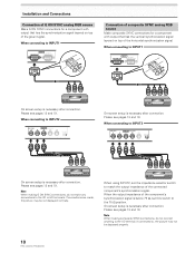
...) On screen setup is below 75 Ω, set the impedance selector switch to , the picture may be displayed properly. 10 PRO-1000HD / PRO-800HD Please see pages 18 and 19. When the output impedance of the component's synchronization signal is necessary after connection. Please see pages...'s synchronization signal. On-screen setup is necessary after connection. When using INPUT2, set this switch to the VD or HD terminals. Installation and Connections Connection of G ON SYNC analog RGB source Make G ON SYNC connections for a component with output that has the vertical...
...) On screen setup is below 75 Ω, set the impedance selector switch to , the picture may be displayed properly. 10 PRO-1000HD / PRO-800HD Please see pages 18 and 19. When the output impedance of the component's synchronization signal is necessary after connection. Please see pages...'s synchronization signal. On-screen setup is necessary after connection. When using INPUT2, set this switch to the VD or HD terminals. Installation and Connections Connection of G ON SYNC analog RGB source Make G ON SYNC connections for a component with output that has the vertical...
Owner's Manual
Page 15
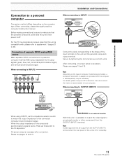
...is off or in standby. 11 PRO-1000HD / PRO-800HD Note A video signal will not be necessary. Connection of the connected computer's synchronization signal. When connecting to INPUT2 (ON SYNC) G B INPUT2 (H/V SYNC) R HD VD 7Ω5Ô2k.Ω2 Installation and Connections When connecting to INPUT1...with the computer or sold separately may be output from the OUTPUT (INPUT1) terminal. Please see pages 18 and 19. Installation and Connections Connection to a personal computer Connection method differs depending on both units. Secure by tightening the terminal screws on ...
...is off or in standby. 11 PRO-1000HD / PRO-800HD Note A video signal will not be necessary. Connection of the connected computer's synchronization signal. When connecting to INPUT2 (ON SYNC) G B INPUT2 (H/V SYNC) R HD VD 7Ω5Ô2k.Ω2 Installation and Connections When connecting to INPUT1...with the computer or sold separately may be output from the OUTPUT (INPUT1) terminal. Please see pages 18 and 19. Installation and Connections Connection to a personal computer Connection method differs depending on both units. Secure by tightening the terminal screws on ...
Owner's Manual
Page 16
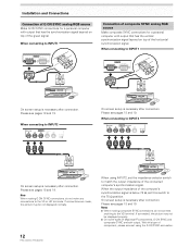
...to the VD terminal. Please see pages 18 and 19. When the output impedance of the computer's synchronization signal is necessary after connection. Installation and Connections Connection of G ON SYNC analog RGB source Make G ON SYNC connections for a personal computer with output that has the vertical...247; On some types of Macintosh® components, G ON SYNC and composite SYNC are made, the picture may be not displayed normally. 12 PRO-1000HD / PRO-800HD When using the G ON SYNC connection. Notes ÷ When making G ON SYNC connections, do not connect anything to the VD or HD ...
...to the VD terminal. Please see pages 18 and 19. When the output impedance of the computer's synchronization signal is necessary after connection. Installation and Connections Connection of G ON SYNC analog RGB source Make G ON SYNC connections for a personal computer with output that has the vertical...247; On some types of Macintosh® components, G ON SYNC and composite SYNC are made, the picture may be not displayed normally. 12 PRO-1000HD / PRO-800HD When using the G ON SYNC connection. Notes ÷ When making G ON SYNC connections, do not connect anything to the VD or HD ...

Owner's Manual
Page 17
...to output the video signal to the S-VIDEO input terminal. AUDIO R INPUT4 VIDEO L OUTPUT To a monitor or a recording device Installation and Connections AV component About DTV Set Top Box Connection To ensure proper connection, please carefully read the instruction manual supplied with are as ...top box output signals that has a video output terminal to the INPUT4 terminal. AUDIO INPUT3 S-VIDEO R L AV component Installation and Connections Connection to INPUT4 Connect an AV component that this display is possible INPUT1 INPUT2 INPUT3 INPUT4 13 PRO-1000HD / PRO-800HD
...to output the video signal to the S-VIDEO input terminal. AUDIO R INPUT4 VIDEO L OUTPUT To a monitor or a recording device Installation and Connections AV component About DTV Set Top Box Connection To ensure proper connection, please carefully read the instruction manual supplied with are as ...top box output signals that has a video output terminal to the INPUT4 terminal. AUDIO INPUT3 S-VIDEO R L AV component Installation and Connections Connection to INPUT4 Connect an AV component that this display is possible INPUT1 INPUT2 INPUT3 INPUT4 13 PRO-1000HD / PRO-800HD
Owner's Manual
Page 18
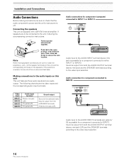
Sound is off. Installation and Connections Audio Connections Before making speaker connections, be sure to match the polarities (+ and -) of the selected video input is possible for component (computer) ... this unit This unit features three audio inputs and one audio output. Note When making connections, be connected to the video input selection. 14 PRO-1000HD / PRO-800HD If speakers are to be sure to check that the audio component's power and the unit's main power is output from both the AUDIO OUTPUT...
Sound is off. Installation and Connections Audio Connections Before making speaker connections, be sure to match the polarities (+ and -) of the selected video input is possible for component (computer) ... this unit This unit features three audio inputs and one audio output. Note When making connections, be connected to the video input selection. 14 PRO-1000HD / PRO-800HD If speakers are to be sure to check that the audio component's power and the unit's main power is output from both the AUDIO OUTPUT...
Owner's Manual
Page 19
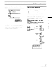
When the connection is made , remote control operation of connected PIONEER components that component will no resistance). 15 PRO-1000HD / PRO-800HD Notes ÷ Make sure the power is output from both the AUDIO OUTPUT terminal (stereo mini jack (L/R)) and the ...SPEAKER terminals according to control. Main unit CONTROL IN OUT CONTROL IN OUT CONTROL IN OUT CONTROL IN OUT The control cables (not supplied) are made to INPUT4. Installation...
When the connection is made , remote control operation of connected PIONEER components that component will no resistance). 15 PRO-1000HD / PRO-800HD Notes ÷ Make sure the power is output from both the AUDIO OUTPUT terminal (stereo mini jack (L/R)) and the ...SPEAKER terminals according to control. Main unit CONTROL IN OUT CONTROL IN OUT CONTROL IN OUT CONTROL IN OUT The control cables (not supplied) are made to INPUT4. Installation...

Owner's Manual
Page 20
... terminal is properly grounded. If you use a power source converter plug, use a power supply voltage other than that the cord is used for efficiency protection. Installation and Connections Power Cord Connection Connect the power cord after all component connections have been completed. 1 2 1 Connect the power cord to a three-pronged grounded outlet... may cause fire or electric shock. ÷ For the plasma display, a three-core power cord with a ground terminal and screw down the ground line. 16 PRO-1000HD / PRO-800HD
... terminal is properly grounded. If you use a power source converter plug, use a power supply voltage other than that the cord is used for efficiency protection. Installation and Connections Power Cord Connection Connect the power cord after all component connections have been completed. 1 2 1 Connect the power cord to a three-pronged grounded outlet... may cause fire or electric shock. ÷ For the plasma display, a three-core power cord with a ground terminal and screw down the ground line. 16 PRO-1000HD / PRO-800HD
Owner's Manual
Page 21
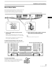
... the clamp may have deteriorated over time and may get damaged when removed. 17 PRO-1000HD / PRO-800HD Once components are designed to be routed to undo once in place. Note Cables can be difficult to the right or left. Installation and Connections * As viewed from the rear of 1 to the main unit Connect...
... the clamp may have deteriorated over time and may get damaged when removed. 17 PRO-1000HD / PRO-800HD Once components are designed to be routed to undo once in place. Note Cables can be difficult to the right or left. Installation and Connections * As viewed from the rear of 1 to the main unit Connect...

Owner's Manual
Page 24
...main unit to the on position to turn off . Operation is not possible while the STANDBY/ON indicator is pressed as described in the section "Installation and Connections" starting on page 8. • Set up the on-screen menu to input signals from components connected to INPUT1 and INPUT2 as follows... mode. If no audio connections are made to this unit, this unit in standby mode. The STANDBY/ON indicator turns green. 20 PRO-1000HD / PRO-800HD FULL 4 Use VOLUME +/- Operations Selecting an Input Source This section explains the basic operation of the picture on and off .
...main unit to the on position to turn off . Operation is not possible while the STANDBY/ON indicator is pressed as described in the section "Installation and Connections" starting on page 8. • Set up the on-screen menu to input signals from components connected to INPUT1 and INPUT2 as follows... mode. If no audio connections are made to this unit, this unit in standby mode. The STANDBY/ON indicator turns green. 20 PRO-1000HD / PRO-800HD FULL 4 Use VOLUME +/- Operations Selecting an Input Source This section explains the basic operation of the picture on and off .

Owner's Manual
Page 38
... connector? Allow condensation to dry thoroughly before using "SCREEN" mode on the menu screen (pages 26, 27). Not a malfunction. 34 PRO-1000HD / PRO-800HD In this case, operate the unit after first turning the main power switch on/off . • No picture Possible Solution • ...devises such as breakdown Problem • The screen is displayed in after ambient temperature exceeds 35 °C (95 °F)(differs depending on installation conditions). Increase the adjustment level of the contrast and check the picture (page 25). • May be caused by radio wave interference...
... connector? Allow condensation to dry thoroughly before using "SCREEN" mode on the menu screen (pages 26, 27). Not a malfunction. 34 PRO-1000HD / PRO-800HD In this case, operate the unit after first turning the main power switch on/off . • No picture Possible Solution • ...devises such as breakdown Problem • The screen is displayed in after ambient temperature exceeds 35 °C (95 °F)(differs depending on installation conditions). Increase the adjustment level of the contrast and check the picture (page 25). • May be caused by radio wave interference...

Other Manual
Page 1
Installation 4.7 Installation GuidGeuide Register your Recorder at www.pioneerelectronics.com
Installation 4.7 Installation GuidGeuide Register your Recorder at www.pioneerelectronics.com

Other Manual
Page 7
...Excessive RENs on the label. If your home has specially wired alarm equipment connected to the telephone line, ensure the installation of this equipment, the Pioneer DVD Recorder with the applicable FCC Part 68 rules and requirements adopted by the total RENs, contact the local telephone ... TiVo, causes harm to an incoming call. If this equipment, the Pioneer DVD Recorder with TiVo, does not disable your right to file a complaint with TiVo, for details. The telephone company may install an AC surge arrestor connected. If trouble is designed to maintain uninterrupted ...
...Excessive RENs on the label. If your home has specially wired alarm equipment connected to the telephone line, ensure the installation of this equipment, the Pioneer DVD Recorder with the applicable FCC Part 68 rules and requirements adopted by the total RENs, contact the local telephone ... TiVo, causes harm to an incoming call. If this equipment, the Pioneer DVD Recorder with TiVo, does not disable your right to file a complaint with TiVo, for details. The telephone company may install an AC surge arrestor connected. If trouble is designed to maintain uninterrupted ...

Other Manual
Page 13
Chapter 1 8 Getting Started Connecting to the Phone Line You don't need to install a new phone jack or phone number-simply use the phone line you already have a home network with the Recorder to connect it to a phone jack. ...
Chapter 1 8 Getting Started Connecting to the Phone Line You don't need to install a new phone jack or phone number-simply use the phone line you already have a home network with the Recorder to connect it to a phone jack. ...


