Owner's Manual
Page 2
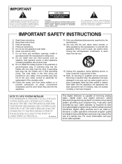
... the cart/apparatus combination to avoid injury from tip-over. 13) Unplug this apparatus near any heat sources such as video-ondemand, a cable operator's enhanced program guide and data-enhanced television services may require the use of time. 14) Refer all servicing to qualified service personnel....other apparatus (including amplifiers) that produce heat. 9) Do not defeat the safety purpose of receiving analog basic, digital basic and digital premium cable television programming by the manufacturer, or sold with dry cloth. 7) Do not block any way, such as power-supply cord or plug is...
... the cart/apparatus combination to avoid injury from tip-over. 13) Unplug this apparatus near any heat sources such as video-ondemand, a cable operator's enhanced program guide and data-enhanced television services may require the use of time. 14) Refer all servicing to qualified service personnel....other apparatus (including amplifiers) that produce heat. 9) Do not defeat the safety purpose of receiving analog basic, digital basic and digital premium cable television programming by the manufacturer, or sold with dry cloth. 7) Do not block any way, such as power-supply cord or plug is...
Owner's Manual
Page 3
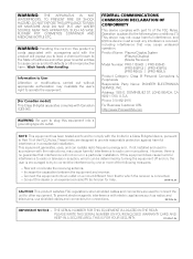
...Product Name: Plasma Display System (Plasma Display) (Media Receiver) Model Number: PRO-1130HD PRO-930HD (PRO-506PU) (PRO-436PU) (PRO-R06U) (PRO-R06U) Product Category: Class B Personal Computers & Peripherals Responsible Party Name: PIONEER ELECTRONICS SERVICE, INC. Address: 1925 E. If this equipment does cause harmful ...or an experienced radio/TV technician for connections. D8-10-1-2_En CAUTION: This product satisfies FCC regulations when shielded cables and connectors are designed to other equipment. NOTE: This equipment has been tested and found to comply with the...
...Product Name: Plasma Display System (Plasma Display) (Media Receiver) Model Number: PRO-1130HD PRO-930HD (PRO-506PU) (PRO-436PU) (PRO-R06U) (PRO-R06U) Product Category: Class B Personal Computers & Peripherals Responsible Party Name: PIONEER ELECTRONICS SERVICE, INC. Address: 1925 E. If this equipment does cause harmful ...or an experienced radio/TV technician for connections. D8-10-1-2_En CAUTION: This product satisfies FCC regulations when shielded cables and connectors are designed to other equipment. NOTE: This equipment has been tested and found to comply with the...
Owner's Manual
Page 4
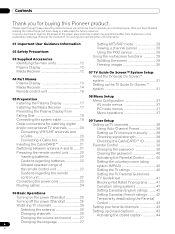
...AV mode menus 37 PC mode menus 37 Menu operations 37 Connecting the system cable 19 Cable connections for watching digital and/or conventional TV channels 20 Connecting VHF/UHF antennas and a Cable 20 Connecting a Cable box 20 Inserting the CableCARD 21 Switching between antenna A and B .......21 ...the Plasma Display 17 Installing the Media Receiver 17 Preventing the Plasma Display from that shown in a safe place for buying this Pioneer product. Contents Contents Thank you will know how to operate your favorite channels 43 Setting up closed captions 43 Activating the closed...
...AV mode menus 37 PC mode menus 37 Menu operations 37 Connecting the system cable 19 Cable connections for watching digital and/or conventional TV channels 20 Connecting VHF/UHF antennas and a Cable 20 Connecting a Cable box 20 Inserting the CableCARD 21 Switching between antenna A and B .......21 ...the Plasma Display 17 Installing the Media Receiver 17 Preventing the Plasma Display from that shown in a safe place for buying this Pioneer product. Contents Contents Thank you will know how to operate your favorite channels 43 Setting up closed captions 43 Activating the closed...
Owner's Manual
Page 6
... the learning function 82 Presetting manufacturer codes ...........82 Manufacture codes 83 Using the remote control unit to control other devices 84 Receiver control buttons 84 Cable control buttons 85 SAT control buttons 86 VCR control buttons 87 DVD/DVR control buttons 88 14 Appendix Troubleshooting 89 Specifications 98 6 En
... the learning function 82 Presetting manufacturer codes ...........82 Manufacture codes 83 Using the remote control unit to control other devices 84 Receiver control buttons 84 Cable control buttons 85 SAT control buttons 86 VCR control buttons 87 DVD/DVR control buttons 88 14 Appendix Troubleshooting 89 Specifications 98 6 En

Owner's Manual
Page 11
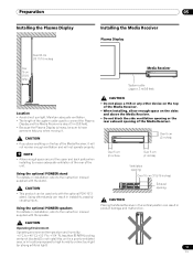
...rear of the Plasma Display. See the side view above are to 0.7 inches) in depth from the use the optional PIONEER mounting products. • PIONEER shall not be used for the installation: Rear view Side view Mounting surface Mounting hole Mounting hole Median line Plasma Display... Mounting bracket (or equivalent item) M8 screw 12 to 18 mm (0.5 to 0.7 inches) SYSTEM CABLE WHITE BLACK Median line CAUTION • ...
...rear of the Plasma Display. See the side view above are to 0.7 inches) in depth from the use the optional PIONEER mounting products. • PIONEER shall not be used for the installation: Rear view Side view Mounting surface Mounting hole Mounting hole Median line Plasma Display... Mounting bracket (or equivalent item) M8 screw 12 to 18 mm (0.5 to 0.7 inches) SYSTEM CABLE WHITE BLACK Median line CAUTION • ...
Owner's Manual
Page 12
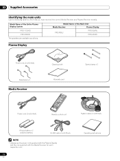
Model Name of the Entire Plasma Display System PRO-1130HD PRO-930HD Model Name of the Main Unit Media Receiver Plasma Display PRO-R06U PRO-506PU PRO-436PU The speakers are available as options. 03 Supplied Accessories Supplied Accessories Identifying the main units ...215; 3 Media Receiver Cleaning cloth Warranty card Speed clamp × 3 Power cord (2 m/6.6 feet) Remote control unit System cable (3 m/9.8 feet) AA size battery × 2 (Alkaline battery) G-LINK cable (3 m/9.8 feet) NOTE • Always use the power cord supplied with the Plasma Display and the one supplied with the...
Model Name of the Entire Plasma Display System PRO-1130HD PRO-930HD Model Name of the Main Unit Media Receiver Plasma Display PRO-R06U PRO-506PU PRO-436PU The speakers are available as options. 03 Supplied Accessories Supplied Accessories Identifying the main units ...215; 3 Media Receiver Cleaning cloth Warranty card Speed clamp × 3 Power cord (2 m/6.6 feet) Remote control unit System cable (3 m/9.8 feet) AA size battery × 2 (Alkaline battery) G-LINK cable (3 m/9.8 feet) NOTE • Always use the power cord supplied with the Plasma Display and the one supplied with the...

Owner's Manual
Page 13
Part Names Part Names Plasma Display Front view 2 1 3 Rear view 04 1 a POWER button 2 STANDBY indicator Lights red when the unit is in standby mode. (page 25) 3 POWER ON indicator Lights blue when the Plasma Display is operating. (page 25) 4 Remote control sensor 4 5 SYSTEM CABLE WHITE BLACK SYSTEM CABLE WHITE BLACK 6 5 SPEAKER (R/L) terminals 6 SYSTEM CABLE terminal (BLACK) 7 8 7 SYSTEM CABLE terminal (WHITE) 8 AC IN terminal 13 En
Part Names Part Names Plasma Display Front view 2 1 3 Rear view 04 1 a POWER button 2 STANDBY indicator Lights red when the unit is in standby mode. (page 25) 3 POWER ON indicator Lights blue when the Plasma Display is operating. (page 25) 4 Remote control sensor 4 5 SYSTEM CABLE WHITE BLACK SYSTEM CABLE WHITE BLACK 6 5 SPEAKER (R/L) terminals 6 SYSTEM CABLE terminal (BLACK) 7 8 7 SYSTEM CABLE terminal (WHITE) 8 AC IN terminal 13 En

Owner's Manual
Page 15
... SERVICE ONLY R-AUDIO-L VIDEO S-VIDEO INPUT 1 Y CB / PB COMPONENT VIDEO CR / PR INPUT 1 INPUT 3 HDMI BLACK WHITE SYSTEM CABLE AC IN 17 9 10 11 12 13 14 1516 18 19 20 21 1 ANT/CABLE A IN terminal 2 MONITOR OUT terminals (AUDIO) 3 MONITOR OUT terminal (VIDEO) 4 G-LINK terminal 5 i.LINK terminals 6 SUB WOOFER terminal 7 DIGITAL...
... SERVICE ONLY R-AUDIO-L VIDEO S-VIDEO INPUT 1 Y CB / PB COMPONENT VIDEO CR / PR INPUT 1 INPUT 3 HDMI BLACK WHITE SYSTEM CABLE AC IN 17 9 10 11 12 13 14 1516 18 19 20 21 1 ANT/CABLE A IN terminal 2 MONITOR OUT terminals (AUDIO) 3 MONITOR OUT terminal (VIDEO) 4 G-LINK terminal 5 i.LINK terminals 6 SUB WOOFER terminal 7 DIGITAL...
Owner's Manual
Page 17
... of the Media Receiver. • When installing, allow enough space on installation, refer to ensure adequate ventilation of the rear of the system cable used only with the speaker. ON STANDBY REC TIMER CAUTION Operating Environment Operating environment temperature and humidity: +0 °C to +40 °C ... around the upper and back parts when installing to the instruction manual supplied with the optional PDK-1013 stand. Using the optional PIONEER speakers For details on the sides and above the Media Receiver. • Do not block the side ventilation opening or the ...
... of the Media Receiver. • When installing, allow enough space on installation, refer to ensure adequate ventilation of the rear of the system cable used only with the speaker. ON STANDBY REC TIMER CAUTION Operating Environment Operating environment temperature and humidity: +0 °C to +40 °C ... around the upper and back parts when installing to the instruction manual supplied with the optional PDK-1013 stand. Using the optional PIONEER speakers For details on the sides and above the Media Receiver. • Do not block the side ventilation opening or the ...
Owner's Manual
Page 19
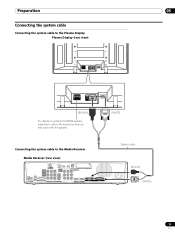
Preparation 05 Connecting the system cable Connecting the system cable to the Plasma Display Plasma Display (rear view) SYSTEM CABLE WHITE BLACK SYSTEM CABLE WHITE BLACK (BLACK) For details on optional PIONEER speaker installation, refer to the instruction manual that came with the speaker. (WHITE) Connecting the system cable to the Media Receiver Media Receiver (rear view...
Preparation 05 Connecting the system cable Connecting the system cable to the Plasma Display Plasma Display (rear view) SYSTEM CABLE WHITE BLACK SYSTEM CABLE WHITE BLACK (BLACK) For details on optional PIONEER speaker installation, refer to the instruction manual that came with the speaker. (WHITE) Connecting the system cable to the Media Receiver Media Receiver (rear view...
Owner's Manual
Page 20
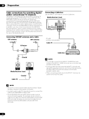
...-L VIDEO S-VIDEO INPUT 1 COM V Connecting VHF/UHF antennas and a Cable VHF antenna UHF antenna U/Vmixer AV cable (commercially available) Cable TV Coaxial ANT B IN ANT/ CABLE A IN Media Receiver (rear) Cable TV Coaxial Cable box NOTE • You can connect that supports digital TV channels and ...VIDEO terminal; use a commercially available S-Video cable. • If using a Cable box that terminal to the ANT/CABLE A IN terminal using cable TV to watch cable TV channels, be careful not to the ANT/CABLE A IN terminal. • The ANT/CABLE A IN and ANT B IN terminals must...
...-L VIDEO S-VIDEO INPUT 1 COM V Connecting VHF/UHF antennas and a Cable VHF antenna UHF antenna U/Vmixer AV cable (commercially available) Cable TV Coaxial ANT B IN ANT/ CABLE A IN Media Receiver (rear) Cable TV Coaxial Cable box NOTE • You can connect that supports digital TV channels and ...VIDEO terminal; use a commercially available S-Video cable. • If using a Cable box that terminal to the ANT/CABLE A IN terminal using cable TV to watch cable TV channels, be careful not to the ANT/CABLE A IN terminal. • The ANT/CABLE A IN and ANT B IN terminals must...
Owner's Manual
Page 21
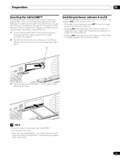
...service presents various types of the Media Receiver, and remove the cover while releasing the tab's latch. S400 (TS) R-AUDIO-L DIOGPITTAICLASOLUUBT WOOFER Cable CARD BLACK WHITE STEM CABLE NOTE • Be sure to insert only the specified CableCARD™. • Do not insert a PC card. • When you...POD service provided by pressing ANT on the rear of useful information, using HTML text. 1 Confirm that the ANT/CABLE A IN terminal has been connected with the coaxial cable from the other antenna. • Pressing ANT while watching in the 2-screen mode (TV image and video image)...
...service presents various types of the Media Receiver, and remove the cover while releasing the tab's latch. S400 (TS) R-AUDIO-L DIOGPITTAICLASOLUUBT WOOFER Cable CARD BLACK WHITE STEM CABLE NOTE • Be sure to insert only the specified CableCARD™. • Do not insert a PC card. • When you...POD service provided by pressing ANT on the rear of useful information, using HTML text. 1 Confirm that the ANT/CABLE A IN terminal has been connected with the coaxial cable from the other antenna. • Pressing ANT while watching in the 2-screen mode (TV image and video image)...
Owner's Manual
Page 23
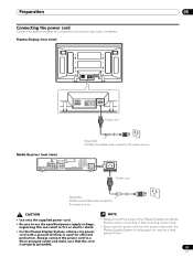
... SERVICE ONLY R-AUDIO-L VIDEO S-VIDEO INPUT 1 Y CB / PB COMPONENT VIDEO CR / PR INPUT 1 INPUT 3 HDMI BLACK WHITE SYSTEM CABLE AC IN AC IN Power cord Noise filter Partially eliminates noise caused by the power source. Always connect the power cord to use the specified ...ground terminal is used for efficient • Always turn off the power of time. protection. Plasma Display (rear view) SYSTEM CABLE WHITE BLACK SYSTEM CABLE WHITE BLACK Power cord Noise filter Partially eliminates noise caused by the power source. Preparation 05 Connecting the power cord Connect the...
... SERVICE ONLY R-AUDIO-L VIDEO S-VIDEO INPUT 1 Y CB / PB COMPONENT VIDEO CR / PR INPUT 1 INPUT 3 HDMI BLACK WHITE SYSTEM CABLE AC IN AC IN Power cord Noise filter Partially eliminates noise caused by the power source. Always connect the power cord to use the specified ...ground terminal is used for efficient • Always turn off the power of time. protection. Plasma Display (rear view) SYSTEM CABLE WHITE BLACK SYSTEM CABLE WHITE BLACK Power cord Noise filter Partially eliminates noise caused by the power source. Preparation 05 Connecting the power cord Connect the...

Owner's Manual
Page 24
... 1 NOTE • Use the supplied bead bands as necessary. * Cable binder Using the cable binders supplied with the stand)* Speaker cable Attaching speed clamps to route the cables. At that the cables are supplied for bunching cables. When the speakers are designed to be careful not to apply any ...clamps Insert [1] into an appropriate hole on the sides (rear view) SYSTEM CABLE WHITE BLACK Speaker cable Speed clamp Speed clamp Cable binder (supplied with the stand, put the speaker and system cables together so that time be difficult to twist the clamp 90°, pulling outward...
... 1 NOTE • Use the supplied bead bands as necessary. * Cable binder Using the cable binders supplied with the stand)* Speaker cable Attaching speed clamps to route the cables. At that the cables are supplied for bunching cables. When the speakers are designed to be careful not to apply any ...clamps Insert [1] into an appropriate hole on the sides (rear view) SYSTEM CABLE WHITE BLACK Speaker cable Speed clamp Speed clamp Cable binder (supplied with the stand, put the speaker and system cables together so that time be difficult to twist the clamp 90°, pulling outward...
Owner's Manual
Page 26
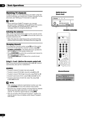
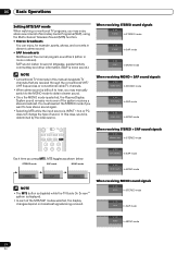
...; To select channel 125 (3-digit channel), press 1, 2, then 5. • To select subchannel 10.01, press 1, 0, • (dot), 0, then 1. • To select subchannel 10.001 (for cable TV), press 1, 0, • (dot), 0, 0, then 1. To clear the channel banner, press INFO. • If you may not display certain types of the screen. NOTE •...
...; To select channel 125 (3-digit channel), press 1, 2, then 5. • To select subchannel 10.01, press 1, 0, • (dot), 0, then 1. • To select subchannel 10.001 (for cable TV), press 1, 0, • (dot), 0, 0, then 1. To clear the channel banner, press INFO. • If you may not display certain types of the screen. NOTE •...
Owner's Manual
Page 28
In this manual designate TV channels that are received through the conventional VHF/ UHF frequencies or conventional cable TV channels. • When stereo sound is difficult to hear, you may enjoy stereo sound and/or Secondary Audio Programs (SAP), using the Multi-channel ...
In this manual designate TV channels that are received through the conventional VHF/ UHF frequencies or conventional cable TV channels. • When stereo sound is difficult to hear, you may enjoy stereo sound and/or Secondary Audio Programs (SAP), using the Multi-channel ...

Owner's Manual
Page 29
... functions Splitting the screen Use the following banner to select the display mode. • Each time you can use the POD service provided by the cable TV company. A or Ant. This service presents various types of program information. Press HOME MENU, 9, 9, then 9 to disappear. B) 5 Program title 6 Program time ... if not included in -picture, and single-screen. Using the POD service If you have watched digital and/or High Definition TV channels over cable, you press SPLIT, the display mode is switched among 2-screen, picture-in broadcast signals. • If you do not setup the TV ...
... functions Splitting the screen Use the following banner to select the display mode. • Each time you can use the POD service provided by the cable TV company. A or Ant. This service presents various types of program information. Press HOME MENU, 9, 9, then 9 to disappear. B) 5 Program title 6 Program time ... if not included in -picture, and single-screen. Using the POD service If you have watched digital and/or High Definition TV channels over cable, you press SPLIT, the display mode is switched among 2-screen, picture-in broadcast signals. • If you do not setup the TV ...
Owner's Manual
Page 31
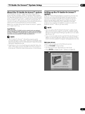
...settings and selected items, the order of the setup screens may differ from the one of listings may take up leads you should leave the cable box On and the TV Off in which TV Guide On Screen™ has not yet been setup. Legal Notices In the United States,...International, Inc. Receipt of all eight days of its affiliates. Follow the instructions shown on for cable-ready, cable box, and digital cable services as well as over-the-air broadcast. NOTE • Once you connect a cable box through the setup process. In Canada, TV GUIDE is powered on the screens. Immediately ...
...settings and selected items, the order of the setup screens may differ from the one of listings may take up leads you should leave the cable box On and the TV Off in which TV Guide On Screen™ has not yet been setup. Legal Notices In the United States,...International, Inc. Receipt of all eight days of its affiliates. Follow the instructions shown on for cable-ready, cable box, and digital cable services as well as over-the-air broadcast. NOTE • Once you connect a cable box through the setup process. In Canada, TV GUIDE is powered on the screens. Immediately ...

Owner's Manual
Page 33
... you see Screen 5. • If you select "No", you see Screen 12. Screen 6: Cable Box Output Channel • Select the channel used for the cable box. • Press ENTER to the cable box. Screen 4: Do you have Cable? • If you select "Yes", you see Screen 4. • If you select "No...", you see Screen 12. Screen 8: Cable Box Brand Name • Press / to select a cable box brand. • Press ...
... you see Screen 5. • If you select "No", you see Screen 12. Screen 6: Cable Box Output Channel • Select the channel used for the cable box. • Press ENTER to the cable box. Screen 4: Do you have Cable? • If you select "Yes", you see Screen 4. • If you select "No...", you see Screen 12. Screen 8: Cable Box Brand Name • Press / to select a cable box brand. • Press ...

Owner's Manual
Page 34
After that screen, you see an additional screen. NOTE Many Cable Boxes require testing more than one code. If you select "Yes", depending on -screen instructions, ... you have an antenna connected? • If you select "Yes", you see Screen 1. Screen 11: Cable Box Tuned to display Screen 15. Screen 10: Cable Box Code Testing • When testing is tested in Screen 10. NOTE If you selected "No" in...you select "No", you see Screen 13. 07 TV Guide On Screen™ System Setup Screen 9: Cable Box Preparation • Follow the on your setup configuration, you may see Screen 13.
After that screen, you see an additional screen. NOTE Many Cable Boxes require testing more than one code. If you select "Yes", depending on -screen instructions, ... you have an antenna connected? • If you select "Yes", you see Screen 1. Screen 11: Cable Box Tuned to display Screen 15. Screen 10: Cable Box Code Testing • When testing is tested in Screen 10. NOTE If you selected "No" in...you select "No", you see Screen 13. 07 TV Guide On Screen™ System Setup Screen 9: Cable Box Preparation • Follow the on your setup configuration, you may see Screen 13.


