Owner's Manual
Page 3
...may cause harmful interference to provide reasonable protection against harmful interference in a secure area. Reorient or relocate the receiving antenna. - To prevent electromagnetic interference with part 15 of the following two conditions: (1) This device may ...other equipment. Product Name: Plasma Display System (Plasma Display) (Media Receiver) Model Number: PDP-5030HD (PDP-503PU) (PDP-R03U) PDP-4330HD (PDP-433PU) (PDP-R03U) Product Category: Class B Personal Computers & Peripherals Responsible Party Name: PIONEER ELECTRONICS (USA), INC., Customer Support Div. Please write this ...
...may cause harmful interference to provide reasonable protection against harmful interference in a secure area. Reorient or relocate the receiving antenna. - To prevent electromagnetic interference with part 15 of the following two conditions: (1) This device may ...other equipment. Product Name: Plasma Display System (Plasma Display) (Media Receiver) Model Number: PDP-5030HD (PDP-503PU) (PDP-R03U) PDP-4330HD (PDP-433PU) (PDP-R03U) Product Category: Class B Personal Computers & Peripherals Responsible Party Name: PIONEER ELECTRONICS (USA), INC., Customer Support Div. Please write this ...
Owner's Manual
Page 4
...Fine Sync. Contents Dear customer 1 Contents 1 Important User Guidance Information 2 Features 3 Supplied accessories 4 Plasma Display 4 Media Receiver 4 Preparation 5 Installing the Plasma Display 5 Setting the system 6 How to route cables 7 Using the remote control unit...regarding remote control unit ...... 8 Inserting the batteries 8 Cautions regarding batteries 8 Part names 9 Plasma Display 9 Media Receiver 10 Remote control unit 11 Watching TV 12 Basic connection 12 Turning on the power 14 Turning off the ... or camcorder 38 Displaying an image of the PIONEER product.
...Fine Sync. Contents Dear customer 1 Contents 1 Important User Guidance Information 2 Features 3 Supplied accessories 4 Plasma Display 4 Media Receiver 4 Preparation 5 Installing the Plasma Display 5 Setting the system 6 How to route cables 7 Using the remote control unit...regarding remote control unit ...... 8 Inserting the batteries 8 Cautions regarding batteries 8 Part names 9 Plasma Display 9 Media Receiver 10 Remote control unit 11 Watching TV 12 Basic connection 12 Turning on the power 14 Turning off the ... or camcorder 38 Displaying an image of the PIONEER product.

Owner's Manual
Page 7
Media Receiver Power cord Remote control unit Two AA size batteries (Alkaline battery) System cable Operating instruction E-4 Supplied accessories Plasma Display Power cord Cleaning cloth Three speed clamps Three bead bands Warranty card A • Always use the power cord supplied with the Plasma Display and the one supplied with the Media Receiver for each respective unit.
Media Receiver Power cord Remote control unit Two AA size batteries (Alkaline battery) System cable Operating instruction E-4 Supplied accessories Plasma Display Power cord Cleaning cloth Three speed clamps Three bead bands Warranty card A • Always use the power cord supplied with the Plasma Display and the one supplied with the Media Receiver for each respective unit.

Owner's Manual
Page 8
...inch) Over 10 cm (3 15/16 inch ) Locating • Avoid the direct sunlight. Keep enough ventilation. • The length of the Media Receiver it by more than 20 % to 80% RH (cooling vents not blocked) Avoid installing in order to the instruction manual provided with the stand....to connect the Plasma Display and the Media Receiver is about 3 m (118 inch). • Because the Plasma Display is heavy, be sure to sunlight, • Under strong artificial light, • In high humidity, • Poorly ventilated. Using the optional PIONEER stand • For details on installation...
...inch) Over 10 cm (3 15/16 inch ) Locating • Avoid the direct sunlight. Keep enough ventilation. • The length of the Media Receiver it by more than 20 % to 80% RH (cooling vents not blocked) Avoid installing in order to the instruction manual provided with the stand....to connect the Plasma Display and the Media Receiver is about 3 m (118 inch). • Because the Plasma Display is heavy, be sure to sunlight, • Under strong artificial light, • In high humidity, • Poorly ventilated. Using the optional PIONEER stand • For details on installation...

Owner's Manual
Page 9
... cable and the power cord to the Plasma Display Plasma Display (rear view) (bottom view) (WHITE) (GRAY) For details on optional PIONEER speaker installation refer to the Media Receiver System cable (GRAY) (WHITE) Media Receiver (rear view) A B COMPONENT VIDEO INPUT 3 Y PB PR RGB INPUT OUT ANT/CABLE 75Ω MONITOR OUTPUT S-VIDEO VIDEO R-AUDIO-L COMPONENT...
... cable and the power cord to the Plasma Display Plasma Display (rear view) (bottom view) (WHITE) (GRAY) For details on optional PIONEER speaker installation refer to the Media Receiver System cable (GRAY) (WHITE) Media Receiver (rear view) A B COMPONENT VIDEO INPUT 3 Y PB PR RGB INPUT OUT ANT/CABLE 75Ω MONITOR OUTPUT S-VIDEO VIDEO R-AUDIO-L COMPONENT...
Owner's Manual
Page 13
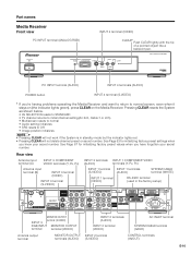
...your secret number. MEDIA RECEIVER PDP-R03U PC INPUT terminal (AUDIO) INPUT 4 terminals (AUDIO) POWER button INPUT 4 terminal (S-VIDEO) * If you know your secret number. See Page 67 for initializing factory preset settings when you 're having problems operating the Media Receiver and want to... terminal (GRAY) Antenna output terminal MONITOR OUTPUT INPUT 2 terminal terminals (AUDIO) (S-VIDEO) CONTROL terminals (IN/OUT) E-10 Part names Media Receiver Front view PC INPUT terminal (ANALOG RGB) STANDBY/ON POWER INPUT 4 terminal (VIDEO) CLEAR* Push CLEAR lightly with the tip of ...
...your secret number. MEDIA RECEIVER PDP-R03U PC INPUT terminal (AUDIO) INPUT 4 terminals (AUDIO) POWER button INPUT 4 terminal (S-VIDEO) * If you know your secret number. See Page 67 for initializing factory preset settings when you 're having problems operating the Media Receiver and want to... terminal (GRAY) Antenna output terminal MONITOR OUTPUT INPUT 2 terminal terminals (AUDIO) (S-VIDEO) CONTROL terminals (IN/OUT) E-10 Part names Media Receiver Front view PC INPUT terminal (ANALOG RGB) STANDBY/ON POWER INPUT 4 terminal (VIDEO) CLEAR* Push CLEAR lightly with the tip of ...
Owner's Manual
Page 15
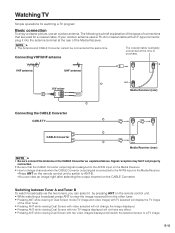
... The coaxial cable is already connected at the same time. VHF antenna UHF antenna B A U/V mixer OUT Media Receiver (rear) Connecting the CABLE Converter CABLE TV A B CABLE Converter OUT Media Receiver (rear) A • Be sure connect the Antenna or the CABLE Converter as explained above. Signal reception may...A and Tuner B To watch broadcasts via the two tuners, you can view an image right after selecting the output channel on the Media Receiver. • How to change the image displayed. • Pressing ANT while viewing Dual Screen with two TV images displayed will switch the...
... The coaxial cable is already connected at the same time. VHF antenna UHF antenna B A U/V mixer OUT Media Receiver (rear) Connecting the CABLE Converter CABLE TV A B CABLE Converter OUT Media Receiver (rear) A • Be sure connect the Antenna or the CABLE Converter as explained above. Signal reception may...A and Tuner B To watch broadcasts via the two tuners, you can view an image right after selecting the output channel on the Media Receiver. • How to change the image displayed. • Pressing ANT while viewing Dual Screen with two TV images displayed will switch the...
Owner's Manual
Page 16
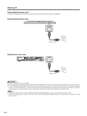
Plasma Display (bottom view) AC INLET Power cord Media Receiver (rear view) A B COMPONENT VIDEO INPUT 3 Y PB PR RGB INPUT OUT ANT/CABLE 75Ω MONITOR OUTPUT S-VIDEO VIDEO R-AUDIO-L COMPONENT VIDEO Y PB PR INPUT 1 RS-... L • Use only the power cord provided. • Do not use an outlet with a ground terminal is used for a long period of Plasma Display and Media Receiver when connecting the power cords. • Disconnect the power cord from the power outlet when the Plasma Display System is not going to be sure...
Plasma Display (bottom view) AC INLET Power cord Media Receiver (rear view) A B COMPONENT VIDEO INPUT 3 Y PB PR RGB INPUT OUT ANT/CABLE 75Ω MONITOR OUTPUT S-VIDEO VIDEO R-AUDIO-L COMPONENT VIDEO Y PB PR INPUT 1 RS-... L • Use only the power cord provided. • Do not use an outlet with a ground terminal is used for a long period of Plasma Display and Media Receiver when connecting the power cords. • Disconnect the power cord from the power outlet when the Plasma Display System is not going to be sure...
Owner's Manual
Page 17
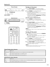
... after approximately 5 seconds. Watching TV Plasma Display STANDBY/ON STANDBY/ON INPUT CHANNEL STANDBY/ON Power indicator MAIN POWER VOLUME STANDBY/ON POWER Media Receiver PLASMA DISPLAY SYSTEM PUSH MEDIA RECEIVER PDP-R03U POWER Power indicator TV CBL VCR DVD TV /SAT /LD /DTV ANT INPUT FRONT AV SURR MTS CC SELECTION SPLIT SELECT ...
... after approximately 5 seconds. Watching TV Plasma Display STANDBY/ON STANDBY/ON INPUT CHANNEL STANDBY/ON Power indicator MAIN POWER VOLUME STANDBY/ON POWER Media Receiver PLASMA DISPLAY SYSTEM PUSH MEDIA RECEIVER PDP-R03U POWER Power indicator TV CBL VCR DVD TV /SAT /LD /DTV ANT INPUT FRONT AV SURR MTS CC SELECTION SPLIT SELECT ...
Owner's Manual
Page 18
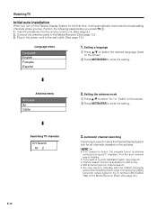
Setting a language 1 Press a/b to select the desired language listed on the screen. 2 Press SET/ENTER to the Media Receiver. (See page 12.) 3. Antenna menu Air/Cable Air Cable 2. A • If no channel is available for ANT-A only. • ANT-B cannot perform channel search. &#... to manually add the CABLE Converter output channel setting (fixed), when connecting the CABLE Converter output signal to the B terminal (ANT/CABLE 75q) on the Media Receiver (Rear).(See page 25.) E-15 And the auto channel search finishes. • If you want to try auto installation again, see page 23. •...
Setting a language 1 Press a/b to select the desired language listed on the screen. 2 Press SET/ENTER to the Media Receiver. (See page 12.) 3. Antenna menu Air/Cable Air Cable 2. A • If no channel is available for ANT-A only. • ANT-B cannot perform channel search. &#... to manually add the CABLE Converter output channel setting (fixed), when connecting the CABLE Converter output signal to the B terminal (ANT/CABLE 75q) on the Media Receiver (Rear).(See page 25.) E-15 And the auto channel search finishes. • If you want to try auto installation again, see page 23. •...

Owner's Manual
Page 35
...is factory preset value. • Return to the previous menu by pressing MENU RETURN. • When a TV program finishes, and the Media Receiver should receives a signal input, but this may not occur. Basic adjustment settings Power Control Power Control setting allows you to reduce the display brightness to ...DVD TOP MENU DTV/SAT GUIDE SET/ ENTER FAVORITE CH DTV/SAT INFO VCR REC A B C D INPUT VOL RECEIVER VOL PLASMA DISPLAY MENU Power Control Energy Save [Standard] Standard Save MENU Power Control No Signal off [Disable] Disable...
...is factory preset value. • Return to the previous menu by pressing MENU RETURN. • When a TV program finishes, and the Media Receiver should receives a signal input, but this may not occur. Basic adjustment settings Power Control Power Control setting allows you to reduce the display brightness to ...DVD TOP MENU DTV/SAT GUIDE SET/ ENTER FAVORITE CH DTV/SAT INFO VCR REC A B C D INPUT VOL RECEIVER VOL PLASMA DISPLAY MENU Power Control Energy Save [Standard] Standard Save MENU Power Control No Signal off [Disable] Disable...
Owner's Manual
Page 37
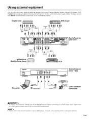
...GRAY) S-VIDEO INPUT 2 VIDEO R-AUDIO-L IN OUT CONTROL (WHITE) AC INLET Media Receiver (rear view) S-VIDEO AV AV Receiver (Built-in Tuner Amp) AV S-VIDEO VCR STANDBY/ON POWER MEDIA RECEIVER PDP-R03U Media Receiver (front view) Computer PC-AUDIO ANALOG RGB AV S-VIDEO Game console/ Camcorder L... • To protect all equipment, always turn off the Media Receiver before connecting to the relevant operation manual (DVD...
...GRAY) S-VIDEO INPUT 2 VIDEO R-AUDIO-L IN OUT CONTROL (WHITE) AC INLET Media Receiver (rear view) S-VIDEO AV AV Receiver (Built-in Tuner Amp) AV S-VIDEO VCR STANDBY/ON POWER MEDIA RECEIVER PDP-R03U Media Receiver (front view) Computer PC-AUDIO ANALOG RGB AV S-VIDEO Game console/ Camcorder L... • To protect all equipment, always turn off the Media Receiver before connecting to the relevant operation manual (DVD...

Owner's Manual
Page 38
... equipment Watching a DVD image Connecting a DVD player You can be selected on the "Input Select" menu. • Refer to a DVD player and other audiovisual equipment. Media Receiver (rear view) Component video cable (commercially available) A B COMPONENT VIDEO INPUT 3 Y PB PR RGB INPUT OUT ANT/CABLE 75Ω MONITOR OUTPUT S-VIDEO VIDEO R-AUDIO-L COMPONENT...
... equipment Watching a DVD image Connecting a DVD player You can be selected on the "Input Select" menu. • Refer to a DVD player and other audiovisual equipment. Media Receiver (rear view) Component video cable (commercially available) A B COMPONENT VIDEO INPUT 3 Y PB PR RGB INPUT OUT ANT/CABLE 75Ω MONITOR OUTPUT S-VIDEO VIDEO R-AUDIO-L COMPONENT...
Owner's Manual
Page 39
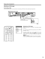
... "INPUT SOURCE" menu. E-36 Using external equipment Watching a VCR image Connecting a VCR You can use the INPUT 2 terminal when connecting a VCR and other audiovisual equipment. Media Receiver (rear view) A B COMPONENT VIDEO INPUT 3 Y PB PR RGB INPUT OUT ANT/CABLE 75Ω MONITOR OUTPUT S-VIDEO VIDEO R-AUDIO-L COMPONENT VIDEO Y PB PR INPUT 1 RS...
... "INPUT SOURCE" menu. E-36 Using external equipment Watching a VCR image Connecting a VCR You can use the INPUT 2 terminal when connecting a VCR and other audiovisual equipment. Media Receiver (rear view) A B COMPONENT VIDEO INPUT 3 Y PB PR RGB INPUT OUT ANT/CABLE 75Ω MONITOR OUTPUT S-VIDEO VIDEO R-AUDIO-L COMPONENT VIDEO Y PB PR INPUT 1 RS...

Owner's Manual
Page 40
... signal type on "Input Select" in clearly, you may need to change the input signal type setting on the front of the Media Receiver when connecting a computer.(See page 39.) E-37 Media Receiver (rear view) Component video cable (commercially available) A B COMPONENT VIDEO INPUT 3 Y PB PR RGB INPUT OUT ANT/CABLE 75Ω MONITOR OUTPUT...
... signal type on "Input Select" in clearly, you may need to change the input signal type setting on the front of the Media Receiver when connecting a computer.(See page 39.) E-37 Media Receiver (rear view) Component video cable (commercially available) A B COMPONENT VIDEO INPUT 3 Y PB PR RGB INPUT OUT ANT/CABLE 75Ω MONITOR OUTPUT...
Owner's Manual
Page 41
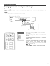
... "INPUT SOURCE" menu. E-38 To connect a game console or view a camcorder, select "INPUT4" from the "INPUT SOURCE" menu using the INPUT 4 terminals. Media Receiver (front view) STANDBY/ON POWER MEDIA RECEIVER PDP-R03U AV cable (commercially available) S-video cable (commercially available) TV CBL VCR DVD TV /SAT /LD /DTV ANT INPUT FRONT AV SURR MTS...
... "INPUT SOURCE" menu. E-38 To connect a game console or view a camcorder, select "INPUT4" from the "INPUT SOURCE" menu using the INPUT 4 terminals. Media Receiver (front view) STANDBY/ON POWER MEDIA RECEIVER PDP-R03U AV cable (commercially available) S-video cable (commercially available) TV CBL VCR DVD TV /SAT /LD /DTV ANT INPUT FRONT AV SURR MTS...
Owner's Manual
Page 42
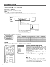
... the input source toggles. • PC INPUT terminals cannot be required for use for audiovisual equipment. Media Receiver (front view) STANDBY/ON POWER MEDIA RECEIVER PDP-R03U RGB cable (commercially available) ø 3.5 mm stereo minijack cable (commercially available) Computer Signal names ...for a list of the Media Receiver when connecting audiovisual equipment with the Plasma Display System. A • The ...
... the input source toggles. • PC INPUT terminals cannot be required for use for audiovisual equipment. Media Receiver (front view) STANDBY/ON POWER MEDIA RECEIVER PDP-R03U RGB cable (commercially available) ø 3.5 mm stereo minijack cable (commercially available) Computer Signal names ...for a list of the Media Receiver when connecting audiovisual equipment with the Plasma Display System. A • The ...

Owner's Manual
Page 43
... supplied) are performed through the sensor on the System side. E-40 After connecting to the Media Receiver form other remote controlled PIONEER components bearing the t logo, remote control operations are mono sound cables with mini plugs (no longer receive signals. To operate a component remotely, point the remote control unit of the connected component at...
... supplied) are performed through the sensor on the System side. E-40 After connecting to the Media Receiver form other remote controlled PIONEER components bearing the t logo, remote control operations are mono sound cables with mini plugs (no longer receive signals. To operate a component remotely, point the remote control unit of the connected component at...

Owner's Manual
Page 45
... factory preset values, 1 Press a/b to select "Reset", and then press SET/ ENTER. 2 Press a/b to select "Yes", and then press SET/ ENTER. • Return to the Media Receiver and switch it up or down. Centers the image by pressing MENU RETURN. • When Auto Sync. adjustment (PC mode only) For automatically adjusting the... TV/SAT/DVD MENU DTV/DVD TOP MENU DTV/SAT GUIDE SET/ ENTER FAVORITE CH DTV/SAT INFO VCR REC A B C D INPUT VOL RECEIVER VOL PLASMA DISPLAY MENU Option Auto Sync.
... factory preset values, 1 Press a/b to select "Reset", and then press SET/ ENTER. 2 Press a/b to select "Yes", and then press SET/ ENTER. • Return to the Media Receiver and switch it up or down. Centers the image by pressing MENU RETURN. • When Auto Sync. adjustment (PC mode only) For automatically adjusting the... TV/SAT/DVD MENU DTV/DVD TOP MENU DTV/SAT GUIDE SET/ ENTER FAVORITE CH DTV/SAT INFO VCR REC A B C D INPUT VOL RECEIVER VOL PLASMA DISPLAY MENU Option Auto Sync.

Owner's Manual
Page 57
...DTV/DVD TOP MENU DTV/SAT GUIDE SET/ ENTER FAVORITE CH DTV/SAT INFO VCR REC A B C D INPUT VOL RECEIVER VOL PLASMA DISPLAY How to temporarily release the V-CHIP BLOCK • The V-CHIP BLOCK is working and censors a broadcast, ... BLOCK as shown below. Method 1: Select Status setting ("On" or "Off") from the Parental CTRL to reactivate BLOCK. Method 3: Switch off the Media Receiver power. displays. 1 Press SET/ENTER while the V-CHIP is working and then the secret number. Method 2: Select V-CHIP setting ("MPAA", "TV Guidelines...
...DTV/DVD TOP MENU DTV/SAT GUIDE SET/ ENTER FAVORITE CH DTV/SAT INFO VCR REC A B C D INPUT VOL RECEIVER VOL PLASMA DISPLAY How to temporarily release the V-CHIP BLOCK • The V-CHIP BLOCK is working and censors a broadcast, ... BLOCK as shown below. Method 1: Select Status setting ("On" or "Off") from the Parental CTRL to reactivate BLOCK. Method 3: Switch off the Media Receiver power. displays. 1 Press SET/ENTER while the V-CHIP is working and then the secret number. Method 2: Select V-CHIP setting ("MPAA", "TV Guidelines...


