
Owner's Manual
Page 2
This reminder is provided to call the CATV system installer's attention to Article 820-40 of the NEC that provides guidelines for proper grounding and, in particular, specifies that the cable ground-shall be connected to the grounding system of cable entry as practical. Note to the point of the building, as close to CATV system installer.
This reminder is provided to call the CATV system installer's attention to Article 820-40 of the NEC that provides guidelines for proper grounding and, in particular, specifies that the cable ground-shall be connected to the grounding system of cable entry as practical. Note to the point of the building, as close to CATV system installer.
Owner's Manual
Page 3
...against harmful interference in accordance with electric appliances such as radios and televisions, use shielded cables and connectors for your enclosed warranty card and keep it in a particular installation. CAUTION: This product satisfies FCC .... Product Name: Plasma Display System (Plasma Display) (Media Receiver) Model Number: PDP-5030HD (PDP-503PU) (PDP-R03U) PDP-4330HD (PDP-433PU) (PDP-R03U) Product Category: Class B Personal Computers & Peripherals Responsible Party Name: PIONEER ELECTRONICS (USA), INC., Customer Support Div. NOTE: This equipment has been tested...
...against harmful interference in accordance with electric appliances such as radios and televisions, use shielded cables and connectors for your enclosed warranty card and keep it in a particular installation. CAUTION: This product satisfies FCC .... Product Name: Plasma Display System (Plasma Display) (Media Receiver) Model Number: PDP-5030HD (PDP-503PU) (PDP-R03U) PDP-4330HD (PDP-433PU) (PDP-R03U) Product Category: Class B Personal Computers & Peripherals Responsible Party Name: PIONEER ELECTRONICS (USA), INC., Customer Support Div. NOTE: This equipment has been tested...
Owner's Manual
Page 4
...37 Enjoying a game console or viewing camcorder images 38 Connecting a game console or camcorder 38 Displaying an image of the PIONEER product. Contents Dear customer 1 Contents 1 Important User Guidance Information 2 Features 3 Supplied accessories 4 Plasma Display 4 Media ...Receiver 4 Preparation 5 Installing the Plasma Display 5 Setting the system 6 How to route cables 7 Using the remote control unit 8 Cautions regarding remote control unit ...... 8 Inserting the batteries 8 Cautions regarding batteries 8 Part names...
...37 Enjoying a game console or viewing camcorder images 38 Connecting a game console or camcorder 38 Displaying an image of the PIONEER product. Contents Dear customer 1 Contents 1 Important User Guidance Information 2 Features 3 Supplied accessories 4 Plasma Display 4 Media ...Receiver 4 Preparation 5 Installing the Plasma Display 5 Setting the system 6 How to route cables 7 Using the remote control unit 8 Cautions regarding remote control unit ...... 8 Inserting the batteries 8 Cautions regarding batteries 8 Part names...

Owner's Manual
Page 7
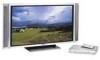
Supplied accessories Plasma Display Power cord Cleaning cloth Three speed clamps Three bead bands Warranty card A • Always use the power cord supplied with the Plasma Display and the one supplied with the Media Receiver for each respective unit. Media Receiver Power cord Remote control unit Two AA size batteries (Alkaline battery) System cable Operating instruction E-4
Supplied accessories Plasma Display Power cord Cleaning cloth Three speed clamps Three bead bands Warranty card A • Always use the power cord supplied with the Plasma Display and the one supplied with the Media Receiver for each respective unit. Media Receiver Power cord Remote control unit Two AA size batteries (Alkaline battery) System cable Operating instruction E-4

Owner's Manual
Page 8
less than two persons. L • If you place anything on top of the system cable used to connect the Plasma Display and the Media Receiver is about 3 m (118 inch). • Because the Plasma Display is heavy, be used only with ... the Media Receiver it by more than 20 % to 80% RH (cooling vents not blocked) Avoid installing in instability causing possible injury. Using the optional PIONEER speakers • For details on installation refer to sunlight, • Under strong artificial light, • In high humidity, • Poorly ventilated. Preparation Installing the Plasma...
less than two persons. L • If you place anything on top of the system cable used to connect the Plasma Display and the Media Receiver is about 3 m (118 inch). • Because the Plasma Display is heavy, be used only with ... the Media Receiver it by more than 20 % to 80% RH (cooling vents not blocked) Avoid installing in instability causing possible injury. Using the optional PIONEER speakers • For details on installation refer to sunlight, • Under strong artificial light, • In high humidity, • Poorly ventilated. Preparation Installing the Plasma...

Owner's Manual
Page 9
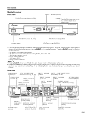
... Plasma Display Plasma Display (rear view) (bottom view) (WHITE) (GRAY) For details on optional PIONEER speaker installation refer to the Media Receiver System cable (GRAY) (WHITE) Media Receiver (rear view) A B COMPONENT VIDEO INPUT 3 Y PB PR RGB INPUT OUT ANT/CABLE 75Ω MONITOR OUTPUT S-VIDEO VIDEO R-AUDIO-L COMPONENT VIDEO Y PB PR INPUT 1 RS...
... Plasma Display Plasma Display (rear view) (bottom view) (WHITE) (GRAY) For details on optional PIONEER speaker installation refer to the Media Receiver System cable (GRAY) (WHITE) Media Receiver (rear view) A B COMPONENT VIDEO INPUT 3 Y PB PR RGB INPUT OUT ANT/CABLE 75Ω MONITOR OUTPUT S-VIDEO VIDEO R-AUDIO-L COMPONENT VIDEO Y PB PR INPUT 1 RS...

Owner's Manual
Page 10
... over time and become damaged if removed. 2 1 Gather cables into an appropriate hole on your routing system. E-7 System cable To the right Speed clamps Bead bands Speaker cable Speaker cable Speed clamps Bead bands System cable Bunch cables using provided speed clamps Attaching speed clamps to the main unit... Connect the speed clamps using the 4 holes marked with provided bead bands A • Cables can be difficult to fix the clamp. Once properly bunched, follow the steps below , depending on the rear of the Plasma Display...
... over time and become damaged if removed. 2 1 Gather cables into an appropriate hole on your routing system. E-7 System cable To the right Speed clamps Bead bands Speaker cable Speaker cable Speed clamps Bead bands System cable Bunch cables using provided speed clamps Attaching speed clamps to the main unit... Connect the speed clamps using the 4 holes marked with provided bead bands A • Cables can be difficult to fix the clamp. Once properly bunched, follow the steps below , depending on the rear of the Plasma Display...
Owner's Manual
Page 13
MEDIA RECEIVER PDP-R03U PC INPUT terminal (AUDIO) INPUT 4 terminals ...3 terminals INPUT 1 COMPONENT VIDEO (AUDIO) terminals (Y, PB, PR) INPUT 1 terminal (S-VIDEO) INPUT 1 terminals (AUDIO) SYSTEM CABLE terminal (WHITE) INPUT 1 terminal (VIDEO) RS-232C terminal (used in standby mode but the indicator lights red. • Pressing...INPUT MONITOR OUTPUT terminal terminal (VIDEO) INPUT 2 terminals (AUDIO) INPUT 2 terminal (VIDEO) AC INLET terminal SYSTEM CABLE terminal (GRAY) Antenna output terminal MONITOR OUTPUT INPUT 2 terminal terminals (AUDIO) (S-VIDEO) CONTROL terminals (IN/OUT)...
MEDIA RECEIVER PDP-R03U PC INPUT terminal (AUDIO) INPUT 4 terminals ...3 terminals INPUT 1 COMPONENT VIDEO (AUDIO) terminals (Y, PB, PR) INPUT 1 terminal (S-VIDEO) INPUT 1 terminals (AUDIO) SYSTEM CABLE terminal (WHITE) INPUT 1 terminal (VIDEO) RS-232C terminal (used in standby mode but the indicator lights red. • Pressing...INPUT MONITOR OUTPUT terminal terminal (VIDEO) INPUT 2 terminals (AUDIO) INPUT 2 terminal (VIDEO) AC INLET terminal SYSTEM CABLE terminal (GRAY) Antenna output terminal MONITOR OUTPUT INPUT 2 terminal terminals (AUDIO) (S-VIDEO) CONTROL terminals (IN/OUT)...
Owner's Manual
Page 15
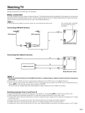
...channel on the remote control unit. • While watching a broadcast press ANT to a TV image. E-12 Watching TV Simple operations for a coaxial cable. Signal reception may fail if not properly connected. • Be sure that are used for watching a TV program Basic connection To enjoy a clearer ...picture, use an outdoor antenna. If your outdoor antenna uses a 75-ohm coaxial cable with two video images displayed will switch the selected screen to view the image received from the other tuner. • Pressing ANT while ...
...channel on the remote control unit. • While watching a broadcast press ANT to a TV image. E-12 Watching TV Simple operations for a coaxial cable. Signal reception may fail if not properly connected. • Be sure that are used for watching a TV program Basic connection To enjoy a clearer ...picture, use an outdoor antenna. If your outdoor antenna uses a 75-ohm coaxial cable with two video images displayed will switch the selected screen to view the image received from the other tuner. • Pressing ANT while ...
Owner's Manual
Page 16
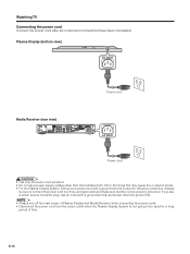
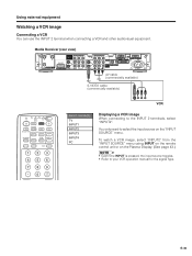
... view) AC INLET Power cord Media Receiver (rear view) A B COMPONENT VIDEO INPUT 3 Y PB PR RGB INPUT OUT ANT/CABLE 75Ω MONITOR OUTPUT S-VIDEO VIDEO R-AUDIO-L COMPONENT VIDEO Y PB PR INPUT 1 RS-232C SYSTEM CABLE (GRAY) S-VIDEO INPUT 2 VIDEO R-AUDIO-L IN OUT CONTROL (WHITE) AC INLET AC INLET Power cord L • Use...
... view) AC INLET Power cord Media Receiver (rear view) A B COMPONENT VIDEO INPUT 3 Y PB PR RGB INPUT OUT ANT/CABLE 75Ω MONITOR OUTPUT S-VIDEO VIDEO R-AUDIO-L COMPONENT VIDEO Y PB PR INPUT 1 RS-232C SYSTEM CABLE (GRAY) S-VIDEO INPUT 2 VIDEO R-AUDIO-L IN OUT CONTROL (WHITE) AC INLET AC INLET Power cord L • Use...
Owner's Manual
Page 18
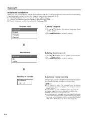
...241;ol 1. Insert the batteries into the remote control unit. (See page 8.) 2. Setting the antenna mode 1 Press a/b to select "Air" or "Cable" on the Plasma Display System for the first time, it will automatically memorize the broadcasting channels where you live. Perform the following steps before you...press TV a. 1. A • If no channel is available for all channels viewable in the power cord to enter the setting. Connect the antenna cable to enter the setting. Watching TV Initial auto installation When you turn on the screen. 2 Press SET/ENTER to the Media Receiver. (See page ...
...241;ol 1. Insert the batteries into the remote control unit. (See page 8.) 2. Setting the antenna mode 1 Press a/b to select "Air" or "Cable" on the Plasma Display System for the first time, it will automatically memorize the broadcasting channels where you live. Perform the following steps before you...press TV a. 1. A • If no channel is available for all channels viewable in the power cord to enter the setting. Connect the antenna cable to enter the setting. Watching TV Initial auto installation When you turn on the screen. 2 Press SET/ENTER to the Media Receiver. (See page ...

Owner's Manual
Page 26
Antenna menu Air/Cable Air Cable Searching TV channels CH Search Air 2 Antenna setting After setting the language, perform settings for all viewable channels in the set it. 4 Press a/b to select "...
Antenna menu Air/Cable Air Cable Searching TV channels CH Search Air 2 Antenna setting After setting the language, perform settings for all viewable channels in the set it. 4 Press a/b to select "...

Owner's Manual
Page 27
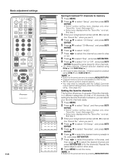
...", and then press SET/ENTER. • Channel search automatically starts. 6 Press MENU to exit the menu. MENU Setup CH Setup Air/Cable CH Search CH Memory Favorites RETURN Automatic channel searching Channel auto search makes the Plasma Display System look for ANT-A only. • ANT-B...SAT INFO VCR REC A B C D INPUT VOL RECEIVER VOL PLASMA DISPLAY MENU Setup CH Setup Air/Cable Air Cable Setting the Air/Cable 1 Press MENU. 2 Press a/b to select "Setup", and then press SET/ [Air] ENTER. • Secret number setting menu displays ...
...", and then press SET/ENTER. • Channel search automatically starts. 6 Press MENU to exit the menu. MENU Setup CH Setup Air/Cable CH Search CH Memory Favorites RETURN Automatic channel searching Channel auto search makes the Plasma Display System look for ANT-A only. • ANT-B...SAT INFO VCR REC A B C D INPUT VOL RECEIVER VOL PLASMA DISPLAY MENU Setup CH Setup Air/Cable Air Cable Setting the Air/Cable 1 Press MENU. 2 Press a/b to select "Setup", and then press SET/ [Air] ENTER. • Secret number setting menu displays ...
Owner's Manual
Page 28
...FAVORITE CH DTV/SAT INFO VCR REC A B C D INPUT VOL RECEIVER VOL PLASMA DISPLAY E-25 MENU Setup CH Setup Air/Cable CH Search CH Memory Favorites RETURN MENU Setup CH Setup CH Memory Air Skip RETURN MENU Setup CH Setup CH Memory Skip Off On MENU... Setup CH Setup Air/Cable CH Search CH Memory Favorites RETURN MENU Setup CH Setup Favorites A B C D MENU Setup CH Setup Favorites A 002 B C D Saving broadcast TV channels to memory 1 Press MENU...
...FAVORITE CH DTV/SAT INFO VCR REC A B C D INPUT VOL RECEIVER VOL PLASMA DISPLAY E-25 MENU Setup CH Setup Air/Cable CH Search CH Memory Favorites RETURN MENU Setup CH Setup CH Memory Air Skip RETURN MENU Setup CH Setup CH Memory Skip Off On MENU... Setup CH Setup Air/Cable CH Search CH Memory Favorites RETURN MENU Setup CH Setup Favorites A B C D MENU Setup CH Setup Favorites A 002 B C D Saving broadcast TV channels to memory 1 Press MENU...
Owner's Manual
Page 37
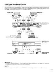
...PB/PR S-VIDEO Y/PB/PR AV A B COMPONENT VIDEO INPUT 3 Y PB PR RGB INPUT OUT ANT/CABLE 75Ω MONITOR OUTPUT S-VIDEO VIDEO R-AUDIO-L COMPONENT VIDEO Y PB PR INPUT 1 RS-232C SYSTEM CABLE (GRAY) S-VIDEO INPUT 2 VIDEO R-AUDIO-L IN OUT CONTROL (WHITE) AC INLET Media Receiver (rear view...) S-VIDEO AV AV Receiver (Built-in Tuner Amp) AV S-VIDEO VCR STANDBY/ON POWER MEDIA RECEIVER PDP-R03U Media Receiver (front view) Computer PC...
...PB/PR S-VIDEO Y/PB/PR AV A B COMPONENT VIDEO INPUT 3 Y PB PR RGB INPUT OUT ANT/CABLE 75Ω MONITOR OUTPUT S-VIDEO VIDEO R-AUDIO-L COMPONENT VIDEO Y PB PR INPUT 1 RS-232C SYSTEM CABLE (GRAY) S-VIDEO INPUT 2 VIDEO R-AUDIO-L IN OUT CONTROL (WHITE) AC INLET Media Receiver (rear view...) S-VIDEO AV AV Receiver (Built-in Tuner Amp) AV S-VIDEO VCR STANDBY/ON POWER MEDIA RECEIVER PDP-R03U Media Receiver (front view) Computer PC...

Owner's Manual
Page 38
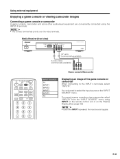
...If the DVD image does not come in the menu. Media Receiver (rear view) Component video cable (commercially available) A B COMPONENT VIDEO INPUT 3 Y PB PR RGB INPUT OUT ANT/CABLE 75Ω MONITOR OUTPUT S-VIDEO VIDEO R-AUDIO-L COMPONENT VIDEO Y PB PR INPUT 1 RS-...232C SYSTEM CABLE (GRAY) S-VIDEO INPUT 2 VIDEO R-AUDIO-L IN OUT CONTROL (WHITE) AC INLET AV cable (commercially available) S-video cable (commercially available) When using INPUT on the remote control unit or on the Plasma Display...
...If the DVD image does not come in the menu. Media Receiver (rear view) Component video cable (commercially available) A B COMPONENT VIDEO INPUT 3 Y PB PR RGB INPUT OUT ANT/CABLE 75Ω MONITOR OUTPUT S-VIDEO VIDEO R-AUDIO-L COMPONENT VIDEO Y PB PR INPUT 1 RS-...232C SYSTEM CABLE (GRAY) S-VIDEO INPUT 2 VIDEO R-AUDIO-L IN OUT CONTROL (WHITE) AC INLET AV cable (commercially available) S-video cable (commercially available) When using INPUT on the remote control unit or on the Plasma Display...
Owner's Manual
Page 39
...Ω MONITOR OUTPUT S-VIDEO VIDEO R-AUDIO-L COMPONENT VIDEO Y PB PR INPUT 1 RS-232C SYSTEM CABLE (GRAY) S-VIDEO INPUT 2 VIDEO R-AUDIO-L IN OUT CONTROL (WHITE) AC INLET AV cable (commercially available) S-VIDEO cable (commercially available) TV CBL VCR DVD TV /SAT /LD /DTV ANT INPUT FRONT AV SURR MTS CC SELECTION SPLIT SELECT ...
...Ω MONITOR OUTPUT S-VIDEO VIDEO R-AUDIO-L COMPONENT VIDEO Y PB PR INPUT 1 RS-232C SYSTEM CABLE (GRAY) S-VIDEO INPUT 2 VIDEO R-AUDIO-L IN OUT CONTROL (WHITE) AC INLET AV cable (commercially available) S-VIDEO cable (commercially available) TV CBL VCR DVD TV /SAT /LD /DTV ANT INPUT FRONT AV SURR MTS CC SELECTION SPLIT SELECT ...

Owner's Manual
Page 40
... menu. Media Receiver (rear view) Component video cable (commercially available) A B COMPONENT VIDEO INPUT 3 Y PB PR RGB INPUT OUT ANT/CABLE 75Ω MONITOR OUTPUT S-VIDEO VIDEO R-AUDIO-L COMPONENT VIDEO Y PB PR INPUT 1 RS-232C SYSTEM CABLE (GRAY) S-VIDEO INPUT 2 VIDEO R-AUDIO-L IN... OUT CONTROL (WHITE) AC INLET AV cable (commercially available) When using RGB cable, select "RGB" for the signal type. • RGB INPUT cannot connect to...
... menu. Media Receiver (rear view) Component video cable (commercially available) A B COMPONENT VIDEO INPUT 3 Y PB PR RGB INPUT OUT ANT/CABLE 75Ω MONITOR OUTPUT S-VIDEO VIDEO R-AUDIO-L COMPONENT VIDEO Y PB PR INPUT 1 RS-232C SYSTEM CABLE (GRAY) S-VIDEO INPUT 2 VIDEO R-AUDIO-L IN... OUT CONTROL (WHITE) AC INLET AV cable (commercially available) When using RGB cable, select "RGB" for the signal type. • RGB INPUT cannot connect to...
Owner's Manual
Page 41
Media Receiver (front view) STANDBY/ON POWER MEDIA RECEIVER PDP-R03U AV cable (commercially available) S-video cable (commercially available) TV CBL VCR DVD TV /SAT /LD /DTV ANT INPUT FRONT AV SURR MTS CC SELECTION SPLIT SELECT SCREEN MODE ...
Media Receiver (front view) STANDBY/ON POWER MEDIA RECEIVER PDP-R03U AV cable (commercially available) S-video cable (commercially available) TV CBL VCR DVD TV /SAT /LD /DTV ANT INPUT FRONT AV SURR MTS CC SELECTION SPLIT SELECT SCREEN MODE ...
Owner's Manual
Page 42
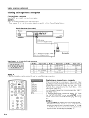
... INPUT on the remote control unit or on the "INPUT SOURCE" menu. Media Receiver (front view) STANDBY/ON POWER MEDIA RECEIVER PDP-R03U RGB cable (commercially available) ø 3.5 mm stereo minijack cable (commercially available) Computer Signal names for 15-pin mini D-sub connecter 543 21 10 9 8 7 6 15 14 13 12 11 Pin No...
... INPUT on the remote control unit or on the "INPUT SOURCE" menu. Media Receiver (front view) STANDBY/ON POWER MEDIA RECEIVER PDP-R03U RGB cable (commercially available) ø 3.5 mm stereo minijack cable (commercially available) Computer Signal names for 15-pin mini D-sub connecter 543 21 10 9 8 7 6 15 14 13 12 11 Pin No...


