Operating Instructions
Page 5
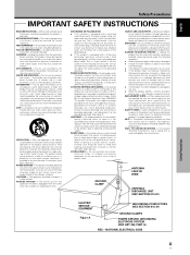
... electrode. If you are unable to qualified service personnel under the following conditions: ÷ When the power-supply cord or plug is a safety feature. Power-supply cords should be taken to keep from the wall outlet and refer servicing to insert the plug into ...instructions should be followed. Never clean with regard to proper grounding of the mast and supporting structure, grounding of power supply to qualified service personnel. The power cord of the grounding type plug. See Figure A. DAMAGE REQUIRING SERVICE - OVERLOADING - English Français Safety...
... electrode. If you are unable to qualified service personnel under the following conditions: ÷ When the power-supply cord or plug is a safety feature. Power-supply cords should be taken to keep from the wall outlet and refer servicing to insert the plug into ...instructions should be followed. Never clean with regard to proper grounding of the mast and supporting structure, grounding of power supply to qualified service personnel. The power cord of the grounding type plug. See Figure A. DAMAGE REQUIRING SERVICE - OVERLOADING - English Français Safety...

Operating Instructions
Page 7
...This Manual 3 Checking Supplied Accessories 5 Part Names and Functions 6 Main Unit 6 Remote Control Unit 7 Connection Panel 8 Installation and Connections 10 Installation of the Unit 10 Connection to INPUT1 and INPUT2 12 Audio Connections 14 Control Cord Connection 15 Power Cord Connection 15 How... Adjustment 26 Manual Adjustment of Screen Position and Clock 27 Other Operations 28 Rewriting the Input Display (INPUT LABEL 28 Power Control Function 29 AUTO FUNCTION 29 Audio Output (AUDIO OUT 30 Additional Information 31 Cleaning 31 Troubleshooting 31 Specifications 34 ...
...This Manual 3 Checking Supplied Accessories 5 Part Names and Functions 6 Main Unit 6 Remote Control Unit 7 Connection Panel 8 Installation and Connections 10 Installation of the Unit 10 Connection to INPUT1 and INPUT2 12 Audio Connections 14 Control Cord Connection 15 Power Cord Connection 15 How... Adjustment 26 Manual Adjustment of Screen Position and Clock 27 Other Operations 28 Rewriting the Input Display (INPUT LABEL 28 Power Control Function 29 AUTO FUNCTION 29 Audio Output (AUDIO OUT 30 Additional Information 31 Cleaning 31 Troubleshooting 31 Specifications 34 ...

Operating Instructions
Page 11
When attaching to the rear of the main unit, be careful not to cover the vents. ÷ Operating Instructions ÷ Warranty Before Proceeding 5 En English Checking Supplied Accessories Check that the following accessories were supplied. 1 Power cord 2 Remote control unit 3 AA (R6) batteries (x 2) 7 Display stands (x 2) Before Proceeding 8 Washers (x 2) 9 Hex hole bolts (x 2) 0 Remote control unit holder 4 Cleaning cloth (for wiping front panel) 5 Speed clamps (x 2) 6 Bead bands (x 2) Use as a holder for the remote control unit.
When attaching to the rear of the main unit, be careful not to cover the vents. ÷ Operating Instructions ÷ Warranty Before Proceeding 5 En English Checking Supplied Accessories Check that the following accessories were supplied. 1 Power cord 2 Remote control unit 3 AA (R6) batteries (x 2) 7 Display stands (x 2) Before Proceeding 8 Washers (x 2) 9 Hex hole bolts (x 2) 0 Remote control unit holder 4 Cleaning cloth (for wiping front panel) 5 Speed clamps (x 2) 6 Bead bands (x 2) Use as a holder for the remote control unit.
Operating Instructions
Page 15
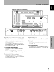
...POWER switch Use to output the audio of 8 -16 Ω (page 14). Connect the audio output jack of components connected to INPUT1 or INPUT2 to this switch to match the output impedance of the connected component's synchronization signal. Part Names and Functions 9 En English Illustration depicts PDP... (INPUT1/2) 1 23 4 56 7 89 0 8 Synchronizing signal impedance selector switch Depending on and off. = AC INLET Use to connect the supplied power cord to an AC outlet (page 15). ~ SPEAKER (L) terminal For connection of the unit on the connections made at INPUT2, it may be ...
...POWER switch Use to output the audio of 8 -16 Ω (page 14). Connect the audio output jack of components connected to INPUT1 or INPUT2 to this switch to match the output impedance of the connected component's synchronization signal. Part Names and Functions 9 En English Illustration depicts PDP... (INPUT1/2) 1 23 4 56 7 89 0 8 Synchronizing signal impedance selector switch Depending on and off. = AC INLET Use to connect the supplied power cord to an AC outlet (page 15). ~ SPEAKER (L) terminal For connection of the unit on the connections made at INPUT2, it may be ...

Operating Instructions
Page 20
... equipped with speaker output jacks for connection to the speaker system (not supplied) specially designed for a component connected to the AUDIO INPUT jacks (stereo mini jack) is possible for use with output that the audio component's power and the unit's main power is output from both output. When connecting to secure the wire...
... equipped with speaker output jacks for connection to the speaker system (not supplied) specially designed for a component connected to the AUDIO INPUT jacks (stereo mini jack) is possible for use with output that the audio component's power and the unit's main power is output from both output. When connecting to secure the wire...
Operating Instructions
Page 21
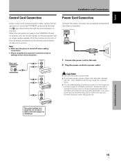
...jack on another unit, the remote sensor of connected PIONEER components that the cord is used for efficiency protection. Notes ÷ Make sure the power is turned off when making control cord connections. The control cables (not supplied) are made to a three-pronged grounded outlet and...cause fire or electric shock. ÷ For the plasma display, a three-core power cord with a ground terminal and screw down the ground line. If you use a power source converter plug, use a power supply voltage other than that component will no resistance). When the connection is made , ...
...jack on another unit, the remote sensor of connected PIONEER components that the cord is used for efficiency protection. Notes ÷ Make sure the power is turned off when making control cord connections. The control cables (not supplied) are made to a three-pronged grounded outlet and...cause fire or electric shock. ÷ For the plasma display, a three-core power cord with a ground terminal and screw down the ground line. If you use a power source converter plug, use a power supply voltage other than that component will no resistance). When the connection is made , ...
Operating Instructions
Page 37
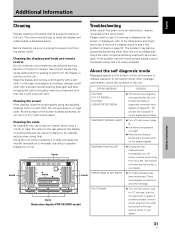
... malfunctioned. Check input signals, connections and other than this unit was purchased. Vents Illustration depicts PDP-503CMX model. If problem persists, remove power plug from its outlet, and consult a Pioneer service center or your dealer. 31 En If displayed, refer to its outlet and consult...unit. About the self diagnosis mode Messages appear on again. Cleaning the screen After dusting, wipe the screen gently using the supplied cleaning cloth or a soft cloth. Wipe the display and remote control gently with a hard object. Additional Information English Additional ...
... malfunctioned. Check input signals, connections and other than this unit was purchased. Vents Illustration depicts PDP-503CMX model. If problem persists, remove power plug from its outlet, and consult a Pioneer service center or your dealer. 31 En If displayed, refer to its outlet and consult...unit. About the self diagnosis mode Messages appear on again. Cleaning the screen After dusting, wipe the screen gently using the supplied cleaning cloth or a soft cloth. Wipe the display and remote control gently with a hard object. Additional Information English Additional ...
Operating Instructions
Page 40
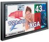
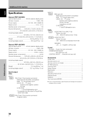
.../CS, VD ... English Additional Information Specifications General (PDP-503CMX) Light emission panel 50 inch plasma display panel Number of pixels 1024 x 768 Power supply AC 100 - 120 V, 50/60 Hz Rated current 2.98 A - 2.48 A Standby power consumption 0.9 W External dimensions ........ 1070 (W) x ... display stand 39.5 kg (87 lbs. 1 oz) General (PDP-433CMX) Light emission panel 43 inch plasma display panel Number of pixels 1280 x 768 Power supply AC 100 - 120 V, 50/60 Hz Rated current 3.8 A - 3.1 A Standby power consumption 1 W External dimensions ........ 1218 (W) x 714 (H) x...
.../CS, VD ... English Additional Information Specifications General (PDP-503CMX) Light emission panel 50 inch plasma display panel Number of pixels 1024 x 768 Power supply AC 100 - 120 V, 50/60 Hz Rated current 2.98 A - 2.48 A Standby power consumption 0.9 W External dimensions ........ 1070 (W) x ... display stand 39.5 kg (87 lbs. 1 oz) General (PDP-433CMX) Light emission panel 43 inch plasma display panel Number of pixels 1280 x 768 Power supply AC 100 - 120 V, 50/60 Hz Rated current 3.8 A - 3.1 A Standby power consumption 1 W External dimensions ........ 1218 (W) x 714 (H) x...
