
Service Manual
Page 2
...necessary test equipment and tools, and have the same safety characteristics as the PIONEER recommended replacement one, shown in the parts list in solder and certain electrical parts contain chemicals which are identified by this product properly and safely, you are ...it is intended for qualified service technicians; PRODUCT SAFETY NOTICE Many electrical and mechanical parts in the appliance have these special safety characteristics are issued from PIONEER. 2 DV-353-K Product Safety is continuously under test Leakage current tester Reading should not be obtained ...
...necessary test equipment and tools, and have the same safety characteristics as the PIONEER recommended replacement one, shown in the parts list in solder and certain electrical parts contain chemicals which are identified by this product properly and safely, you are ...it is intended for qualified service technicians; PRODUCT SAFETY NOTICE Many electrical and mechanical parts in the appliance have these special safety characteristics are issued from PIONEER. 2 DV-353-K Product Safety is continuously under test Leakage current tester Reading should not be obtained ...
Service Manual
Page 3
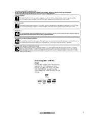
...and noise, and other parts requiring cleaning, proper cleaning should be used in projection monitors, and other regulations), and should keep the original performances of the following the safety instructions described in this manual. 2. DVD-Video Audio-CD Video-CD CD-R CD-RW DV-353-K 3 When you ...find the procedures bearing any of the symbols, be sure to failures or troubles in the product. But improper lubrication or applying glue may be caused during servicing by the appropriate amount.For replacement parts or tools, the ...
...and noise, and other parts requiring cleaning, proper cleaning should be used in projection monitors, and other regulations), and should keep the original performances of the following the safety instructions described in this manual. 2. DVD-Video Audio-CD Video-CD CD-R CD-RW DV-353-K 3 When you ...find the procedures bearing any of the symbols, be sure to failures or troubles in the product. But improper lubrication or applying glue may be caused during servicing by the appropriate amount.For replacement parts or tools, the ...
Service Manual
Page 4
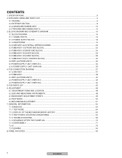
... ...6 2.1 PACKING ...6 2.2 EXTERIOR SECTION ...8 2.3 LOADING MECHANISM ASSY ...10 2.4 TRAVERSE MECHANISM ASSY-S ...14 3. PANEL FACILITIES ...95 4 DV-353-K PCB PARTS LIST ...45 6. BLOCK DIAGRAM AND SCHEMATIC DIAGRAM 16 3.1 BLOCK DIAGRAM ...16 3.1.1 SIGNAL ROUTE ...16 3.1.2 POWER SUPPLY BLOCK ...18 3.1.3 WAVEFORMS ...19 3.2 LOAB ASSY and OVERALL WIRING ...
... ...6 2.1 PACKING ...6 2.2 EXTERIOR SECTION ...8 2.3 LOADING MECHANISM ASSY ...10 2.4 TRAVERSE MECHANISM ASSY-S ...14 3. PANEL FACILITIES ...95 4 DV-353-K PCB PARTS LIST ...45 6. BLOCK DIAGRAM AND SCHEMATIC DIAGRAM 16 3.1 BLOCK DIAGRAM ...16 3.1.1 SIGNAL ROUTE ...16 3.1.2 POWER SUPPLY BLOCK ...18 3.1.3 WAVEFORMS ...19 3.2 LOAB ASSY and OVERALL WIRING ...
Service Manual
Page 6
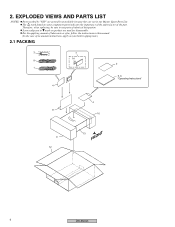
... as you think it appropriate.) 2.1 PACKING 3 8 1 4 7 14 2 5, 6 "Operating Instructions" 4 11 10 9 12 13 FRONT 6 DV-353-K Screws adjacent to use parts of lubricants or glue, follow the instructions in our Master Spare Parts List. EXPLODED VIEWS AND PARTS LIST NOTES: Parts marked by "NSP" are generally unavailable because they are used for disassembly. For the applying...
... as you think it appropriate.) 2.1 PACKING 3 8 1 4 7 14 2 5, 6 "Operating Instructions" 4 11 10 9 12 13 FRONT 6 DV-353-K Screws adjacent to use parts of lubricants or glue, follow the instructions in our Master Spare Parts List. EXPLODED VIEWS AND PARTS LIST NOTES: Parts marked by "NSP" are generally unavailable because they are used for disassembly. For the applying...

Service Manual
Page 7
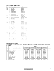
... VHA1296 VHA1298 VHA1298 VHA1298 VHA1298 11 Paper Board 12 Packing Case VHC1088 VHC1088 VHC1089 VHC1089 VHC1089 VHC1089 VHG2237 VHG2187 VHG2169 VHG2158 VHG2160 VHG2197 DV-353-K 7 ADG7022 See Contrast table (2) See Contrast table (2) VHL1051 VRB1285 6 Operating Instructions (French) 7 Remote Control 8 Audio/Video...Contrast table (2) See Contrast table (2) Z23-007 VNK4997 (2) CONTRAST TABLE DV-353-K/KUXJ, KCXJ, DV-353-S/KUXU/CA, DV-250/KUXU, KCXU and DV-251/KUXQ are constructed the same except for the following : Part No. Mark No. Description > 1 Power Cable NSP 2 Warranty Card...
... VHA1296 VHA1298 VHA1298 VHA1298 VHA1298 11 Paper Board 12 Packing Case VHC1088 VHC1088 VHC1089 VHC1089 VHC1089 VHC1089 VHG2237 VHG2187 VHG2169 VHG2158 VHG2160 VHG2197 DV-353-K 7 ADG7022 See Contrast table (2) See Contrast table (2) VHL1051 VRB1285 6 Operating Instructions (French) 7 Remote Control 8 Audio/Video...Contrast table (2) See Contrast table (2) Z23-007 VNK4997 (2) CONTRAST TABLE DV-353-K/KUXJ, KCXJ, DV-353-S/KUXU/CA, DV-250/KUXU, KCXU and DV-251/KUXQ are constructed the same except for the following : Part No. Mark No. Description > 1 Power Cable NSP 2 Warranty Card...
Service Manual
Page 9
... Tray Panel 19 Front Panel Assy 20 Pioneer Badge 25 Screw 26 Bonnet Case S VNK4952 VXA2486 XAM3006 BCZ40P060FZK VXX2821 VNK4973 VXA2496 VAM1129 BCZ40P060FNI VXX2823 VNK4959 VXA2490 VAM1129 BCZ40P060FZK VXX2830 VNK4962 VXA2491 VAM1130 BCZ40P060FZK VXX2831 DV-353-K 9 VWG2344 VWG2345 VWS1515 PF05PP-Q12 PF13PP... 26 Bonnet Case S See Cotrast table (2) (2) CONTRAST TABLE DV-353-K/KUXJ, KCXJ, DV-353-S/KUXU/CA, DV-250/KUXU, KCXU and DV-251/KUXQ are constructed the same except for the following : Part No. Mark No. (1) EXTERIOR PARTS LIST Mark No. Description NSP NSP 1 IRKY Assy 2 PWSB ...
... Tray Panel 19 Front Panel Assy 20 Pioneer Badge 25 Screw 26 Bonnet Case S VNK4952 VXA2486 XAM3006 BCZ40P060FZK VXX2821 VNK4973 VXA2496 VAM1129 BCZ40P060FNI VXX2823 VNK4959 VXA2490 VAM1129 BCZ40P060FZK VXX2830 VNK4962 VXA2491 VAM1130 BCZ40P060FZK VXX2831 DV-353-K 9 VWG2344 VWG2345 VWS1515 PF05PP-Q12 PF13PP... 26 Bonnet Case S See Cotrast table (2) (2) CONTRAST TABLE DV-353-K/KUXJ, KCXJ, DV-353-S/KUXU/CA, DV-250/KUXU, KCXU and DV-251/KUXQ are constructed the same except for the following : Part No. Mark No. (1) EXTERIOR PARTS LIST Mark No. Description NSP NSP 1 IRKY Assy 2 PWSB ...

Service Manual
Page 11
VWT1197 VWT1188 NSP 1 LOAB Assy 6 Flexible Cable (26P) VWG2346 VDA1864 VWG2279 VDA1865 Remarks DV-353-K 11 NSP 1 LOAB Assy 2 Traverse Mechanism Assy-S 3 Loading Motor Assy 4 Motor Pulley 5 Carriage DC Motor / 0.3W See Contrast table (2) VXX2782 VXX2505 PNW1634 PXM1027 6 Flexible Cable (... 23 Tray JGZ17P028FMC Z39-019 VNL1920 (2) CONTRAST TABLE VWT1196, VWT1197 and VWT1188 are constructed the same except for the following : Mark No. (1) LOADING MECHANISM ASSY PARTS LIST Mark No. Description Part No. Symbol and Description VWT1196...
VWT1197 VWT1188 NSP 1 LOAB Assy 6 Flexible Cable (26P) VWG2346 VDA1864 VWG2279 VDA1865 Remarks DV-353-K 11 NSP 1 LOAB Assy 2 Traverse Mechanism Assy-S 3 Loading Motor Assy 4 Motor Pulley 5 Carriage DC Motor / 0.3W See Contrast table (2) VXX2782 VXX2505 PNW1634 PXM1027 6 Flexible Cable (... 23 Tray JGZ17P028FMC Z39-019 VNL1920 (2) CONTRAST TABLE VWT1196, VWT1197 and VWT1188 are constructed the same except for the following : Mark No. (1) LOADING MECHANISM ASSY PARTS LIST Mark No. Description Part No. Symbol and Description VWT1196...

Service Manual
Page 15
• TRAVERSE MECHANISM ASSY-S PARTS LIST Mark No. Description Part No. 1 Spindle Motor 2 Stepping Motor 3 Pickup Assy-S 4 Skew Screw 5 Skew Spring VXM1088 (or VXM1089) VXM1090 (or VXM1091) OXX8003 VBA1080 VBH1335 6 Guide Bar 7 Sub Guide Bar 8 Hold Spring 9 Joint Spring 10 Support Spring VLL1514 VLL1515 VNC1017 VNC1019 VNC1020 NSP 11 Mechanism Chassis 12 Slider 13 Spacer 14 Joint 15 FFC Holder VNE2248 VNL1811 VNL1913 VNL1914 VNL1915 16 Screw 17 Tapping Screw 18 Screw 19 Damper Sheet BBZ20P050FZK OBA8009 PMA26P100FMC VEB1335 DV-353-K 15
• TRAVERSE MECHANISM ASSY-S PARTS LIST Mark No. Description Part No. 1 Spindle Motor 2 Stepping Motor 3 Pickup Assy-S 4 Skew Screw 5 Skew Spring VXM1088 (or VXM1089) VXM1090 (or VXM1091) OXX8003 VBA1080 VBH1335 6 Guide Bar 7 Sub Guide Bar 8 Hold Spring 9 Joint Spring 10 Support Spring VLL1514 VLL1515 VNC1017 VNC1019 VNC1020 NSP 11 Mechanism Chassis 12 Slider 13 Spacer 14 Joint 15 FFC Holder VNE2248 VNL1811 VNL1913 VNL1914 VNL1915 16 Screw 17 Tapping Screw 18 Screw 19 Damper Sheet BBZ20P050FZK OBA8009 PMA26P100FMC VEB1335 DV-353-K 15
Service Manual
Page 21
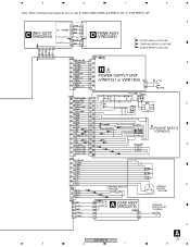
5 6 7 8 Note : When ordering service parts, be sure to refer to "EXPLODED VIEWS and PARTS LIST" or "PCB PARTS LIST" A C IRKY ASSY (VWG2344) for ##XCN type D PSWB ASSY (VWG2345) (F) : FOCUS SERVO LOOP LINE (T) : TRACKING SERVO LOOP LINE (S) : SLIDER SERVO LOOP LINE B H POWER SUPPLY UNIT (VWR1351 or VWR1353) C (F) (F) (T) (F) (F) (F) (F) (T) (F) (F) (F) (T) (T) (F) PICKUP ASSY-S (OXX8003) D STEPPING MOTOR (S) : VXM1090 (S) (S) (S) E SPINDLE MOTOR : VXX1088 A LOAB ASSY (VWG2279) LOADING MOTOR ASSY : VXX2505 F ABCDA DV-353-K 21 5 6 7 8
5 6 7 8 Note : When ordering service parts, be sure to refer to "EXPLODED VIEWS and PARTS LIST" or "PCB PARTS LIST" A C IRKY ASSY (VWG2344) for ##XCN type D PSWB ASSY (VWG2345) (F) : FOCUS SERVO LOOP LINE (T) : TRACKING SERVO LOOP LINE (S) : SLIDER SERVO LOOP LINE B H POWER SUPPLY UNIT (VWR1351 or VWR1353) C (F) (F) (T) (F) (F) (F) (F) (T) (F) (F) (F) (T) (T) (F) PICKUP ASSY-S (OXX8003) D STEPPING MOTOR (S) : VXM1090 (S) (S) (S) E SPINDLE MOTOR : VXX1088 A LOAB ASSY (VWG2279) LOADING MOTOR ASSY : VXX2505 F ABCDA DV-353-K 21 5 6 7 8

Service Manual
Page 34
.... REPLACE ONLY WITH SAME TYPE NO. 491002 MFD, BY LITTELFUSE INC. FOR P104 (AEK7067). CN101 AEK7066 1.6A AEK7067 2.0A AEK7012 1.6A B 1/3 CN401 2 2 DV-353-K 3 3 4 E 4 C2, C6, C106, C303, Z1: STANDBY • NOTE FOR FUSE REPLACEMENT CAUTION -FOR CONTINUED PROTECTION AGAINST RISK OF FIRE. FOR P103... UNIT (VWR1351) A B C D E F E 34 1 AC IN E POWER SUPPLY UNIT (VWR1351) NOTE OF SPARE PARTS IN POWER SUPPLY (SYPS) UNIT • In case of repairing, use the described parts only to prevent an accident. • Please write the red mark on the board when the primary section of...
.... REPLACE ONLY WITH SAME TYPE NO. 491002 MFD, BY LITTELFUSE INC. FOR P104 (AEK7067). CN101 AEK7066 1.6A AEK7067 2.0A AEK7012 1.6A B 1/3 CN401 2 2 DV-353-K 3 3 4 E 4 C2, C6, C106, C303, Z1: STANDBY • NOTE FOR FUSE REPLACEMENT CAUTION -FOR CONTINUED PROTECTION AGAINST RISK OF FIRE. FOR P103... UNIT (VWR1351) A B C D E F E 34 1 AC IN E POWER SUPPLY UNIT (VWR1351) NOTE OF SPARE PARTS IN POWER SUPPLY (SYPS) UNIT • In case of repairing, use the described parts only to prevent an accident. • Please write the red mark on the board when the primary section of...

Service Manual
Page 35
FOR CP2, CP3 (AEK7066). FOR CP1 (AEK7067). 6 6 DV-353-K 7 7 REK1077 1.6A CN1 AC IN AEK7012 1.6A AEK7063 800mA AEK7066 1.6A AEK7067 2.0A AEK7066 1.6A B 1/3 CN401 C19, R25, VS1: STANDBY • NOTE FOR FUSE REPLACEMENT ... the board when the primary section of POWER SUPPLY (SYPS) Unit is repaired. • Please take care to keep the space, not touching other parts when replacing the parts. CAUTION : FOR CONTINUED PROTECTION AGAINST RISK OF FIRE. FOR CP5 (AEK7063). REPLACE ONLY WITH SAME TYPE NO. 491.800 MFD, BY LITTELFUSE INC...
FOR CP2, CP3 (AEK7066). FOR CP1 (AEK7067). 6 6 DV-353-K 7 7 REK1077 1.6A CN1 AC IN AEK7012 1.6A AEK7063 800mA AEK7066 1.6A AEK7067 2.0A AEK7066 1.6A B 1/3 CN401 C19, R25, VS1: STANDBY • NOTE FOR FUSE REPLACEMENT ... the board when the primary section of POWER SUPPLY (SYPS) Unit is repaired. • Please take care to keep the space, not touching other parts when replacing the parts. CAUTION : FOR CONTINUED PROTECTION AGAINST RISK OF FIRE. FOR CP5 (AEK7063). REPLACE ONLY WITH SAME TYPE NO. 491.800 MFD, BY LITTELFUSE INC...

Service Manual
Page 37
... D G SD G S Field effect transistor 3. Symbol In PCB Diagrams Symbol In Schematic Diagrams B C EB C E Part Name BCE Transistor BCE B C EB C E Transistor with the schematic diagram. 4. For further information for several destinations.... DIAGRAMS : 1. A comparison between the main parts of PCB diagrams. Connector Capacitor SIDE A B P.C.Board Chip Part SIDE B Resistor array 3-terminal regulator C D 4.1 LOAB ASSY A LOAB ASSY M LOADING MOTOR ASSY CN11 B CN52 SIDE A (VNP1836-B) A 5 DV-353-K 6 SIDE B 7 E F A 37 8 Part numbers in PCB diagrams match those in the ...
... D G SD G S Field effect transistor 3. Symbol In PCB Diagrams Symbol In Schematic Diagrams B C EB C E Part Name BCE Transistor BCE B C EB C E Transistor with the schematic diagram. 4. For further information for several destinations.... DIAGRAMS : 1. A comparison between the main parts of PCB diagrams. Connector Capacitor SIDE A B P.C.Board Chip Part SIDE B Resistor array 3-terminal regulator C D 4.1 LOAB ASSY A LOAB ASSY M LOADING MOTOR ASSY CN11 B CN52 SIDE A (VNP1836-B) A 5 DV-353-K 6 SIDE B 7 E F A 37 8 Part numbers in PCB diagrams match those in the ...

Service Manual
Page 39
... R689 C649 R576 R581 R587 R580 R601 R578 R579 R591 R542 FC DC WARNING THIS PRODUCT CONTAINS LEAD IN SOLDER AND CERTAIN ELECTRICAL PARTS CONTAIN CHEMICALS WHICH ARE KNOWN TO THE STATE OF CALIFORNIA TO CAUSE CANCER,BIRTH DEFECTS OR OTHER REPRODUCTIVE HARM. PROPOSITION 65 17 C803...R955 R590 1 7 1 52 9 1 7 SIDE A A B C D E C604 C601 IC441 IC421 IC431 Q602 Q606 Q604 Q607 Q603 Q605 Q711 IC771 IC711 Q772 IC921 Q771 IC901 DV-353-K 5 6 Q796 Q762 IC731 Q761 Q794 Q792 Q791 Q795 IC801 Q941 7 Q768 Q769 Q766 Q767 F B 39 8 HEALTH & SAFETY CODE SECTION 25249.2 -
... R689 C649 R576 R581 R587 R580 R601 R578 R579 R591 R542 FC DC WARNING THIS PRODUCT CONTAINS LEAD IN SOLDER AND CERTAIN ELECTRICAL PARTS CONTAIN CHEMICALS WHICH ARE KNOWN TO THE STATE OF CALIFORNIA TO CAUSE CANCER,BIRTH DEFECTS OR OTHER REPRODUCTIVE HARM. PROPOSITION 65 17 C803...R955 R590 1 7 1 52 9 1 7 SIDE A A B C D E C604 C601 IC441 IC421 IC431 Q602 Q606 Q604 Q607 Q603 Q605 Q711 IC771 IC711 Q772 IC921 Q771 IC901 DV-353-K 5 6 Q796 Q762 IC731 Q761 Q794 Q792 Q791 Q795 IC801 Q941 7 Q768 Q769 Q766 Q767 F B 39 8 HEALTH & SAFETY CODE SECTION 25249.2 -

Service Manual
Page 45
...BA10358FV BA18BC0FP BA4560F BA6664FM K4S641632F-TC75 K6T1008V2E-TB70 L6315ATXXTY M56788AFP MM1385EN MM1565AF MM1567AJ NJM78L05A PCM1742KE PE5314A PQ025EZ01ZP PQ070XZ02ZP PST3228 STI5519AVB-B0C TC7WU04FU DV-353-K 45 Mark No. Description 7 LIST OF ASSEMBLIES KUXJ and KCXJ Types NSP 1..LOADING MECHANISM ASSY NSP 2..LOAB ASSY ...1..FJMB ASSY NSP NSP NSP 1..KEYB ASSY 2..IRKY ASSY 2..PSWB ASSY > 1..POWER SUPPLY UNIT Part No. B PARTS Description LISTPart No. Ex.1 When there are 2 effective digits (any digit apart from 0), such as 560 ohm and 47k ohm...
...BA10358FV BA18BC0FP BA4560F BA6664FM K4S641632F-TC75 K6T1008V2E-TB70 L6315ATXXTY M56788AFP MM1385EN MM1565AF MM1567AJ NJM78L05A PCM1742KE PE5314A PQ025EZ01ZP PQ070XZ02ZP PST3228 STI5519AVB-B0C TC7WU04FU DV-353-K 45 Mark No. Description 7 LIST OF ASSEMBLIES KUXJ and KCXJ Types NSP 1..LOADING MECHANISM ASSY NSP 2..LOAB ASSY ...1..FJMB ASSY NSP NSP NSP 1..KEYB ASSY 2..IRKY ASSY 2..PSWB ASSY > 1..POWER SUPPLY UNIT Part No. B PARTS Description LISTPart No. Ex.1 When there are 2 effective digits (any digit apart from 0), such as 560 ohm and 47k ohm...

Service Manual
Page 46
...VSS1167 VSS1168 IRKY ASSY SEMICONDUCTORS IC301 COILS AND FILTERS L301, L311 CHIP BEADS SWITCHES AND RELAYS S301-S306 SPS-444L-H VTL1084 ASG7013 46 DV-353-K Description IC603 Q300, Q602-Q607, Q762 Q81, Q83 Q103, Q104, Q82, Q941 Q766, Q767 Q652 Q711, Q761, Q805, Q807..., C952 C30 C411, C423, C431, C601 C610, C611, C613, C615, C629 C635, C636, C741 C734, C754 (330P/50V) Part No. VYW1890 2SA1037K 2SA1602A 2SC2412K 2SD2114K DTC114TK DTC114YK HN1A01F PDTA124EK RN4982 RB501V-40 UDZS6.2B LAU3R3J LCYA2R2J2520 LCYA2R7J2520 VTL1083 VTL1089 CCSRCH100D50 CCSRCH151J50 CCSRCH180J50 CCSRCH330J50 ...
...VSS1167 VSS1168 IRKY ASSY SEMICONDUCTORS IC301 COILS AND FILTERS L301, L311 CHIP BEADS SWITCHES AND RELAYS S301-S306 SPS-444L-H VTL1084 ASG7013 46 DV-353-K Description IC603 Q300, Q602-Q607, Q762 Q81, Q83 Q103, Q104, Q82, Q941 Q766, Q767 Q652 Q711, Q761, Q805, Q807..., C952 C30 C411, C423, C431, C601 C610, C611, C613, C615, C629 C635, C636, C741 C734, C754 (330P/50V) Part No. VYW1890 2SA1037K 2SA1602A 2SC2412K 2SD2114K DTC114TK DTC114YK HN1A01F PDTA124EK RN4982 RB501V-40 UDZS6.2B LAU3R3J LCYA2R2J2520 LCYA2R7J2520 VTL1083 VTL1089 CCSRCH100D50 CCSRCH151J50 CCSRCH180J50 CCSRCH330J50 ...

Service Manual
Page 47
... POWER SUPPLY UNIT (VWR1353) OTHERS > CP5 PROTECTOR (800mA) > CP2, CP3 PROTECTOR (1.6A) > CP1 PROTECTOR (2A) > F1 FUSE (1.6A) AEK7063 AEK7066 AEK7067 REK1077 Mark No. Description Part No. DV-353-K 47 Mark No. Description CAPACITORS C301 RESISTORS All Resistors OTHERS 3P CABLE HOLDER J301 3P JUMPER WIRE CN301 CONNECTOR...
... POWER SUPPLY UNIT (VWR1353) OTHERS > CP5 PROTECTOR (800mA) > CP2, CP3 PROTECTOR (1.6A) > CP1 PROTECTOR (2A) > F1 FUSE (1.6A) AEK7063 AEK7066 AEK7067 REK1077 Mark No. Description Part No. DV-353-K 47 Mark No. Description CAPACITORS C301 RESISTORS All Resistors OTHERS 3P CABLE HOLDER J301 3P JUMPER WIRE CN301 CONNECTOR...

Service Manual
Page 48
... [Electrical Part] Electrical adjustments are not required. Cautions: After adjustment, adjustment screw locks with the Screw tight. 12 Tangential adjustment screw 12 Radial adjustment screw 6.2 JIGS AND MEASURING INSTRUMENTS Screwdriver (large) Screwdriver (medium) TV monitor Test mode remote control unit (GGF1067) Precise screwdriver 48 DVD test disc (GGV1025) Screw tight (GYL1001) DV-353-K 6.
... [Electrical Part] Electrical adjustments are not required. Cautions: After adjustment, adjustment screw locks with the Screw tight. 12 Tangential adjustment screw 12 Radial adjustment screw 6.2 JIGS AND MEASURING INSTRUMENTS Screwdriver (large) Screwdriver (medium) TV monitor Test mode remote control unit (GGF1067) Precise screwdriver 48 DVD test disc (GGV1025) Screw tight (GYL1001) DV-353-K 6.

Service Manual
Page 49
... when replaced Pickup, Traverse Mechanism and Spindle Motor. ESC CLEAR GGF1067 Test mode remote control unit (It is necessary when performed adjustment procedure Ÿ.) DV-353-K 49 6.3 NECESSARY ADJUSTMENT POINTS When Exchange Parts of Mechanism Assy Adjustment Points Exchange the Pickup Mechanical point ~, Ÿ, ! ∗ After adjustment, screw locks with the Screw tight.
... when replaced Pickup, Traverse Mechanism and Spindle Motor. ESC CLEAR GGF1067 Test mode remote control unit (It is necessary when performed adjustment procedure Ÿ.) DV-353-K 49 6.3 NECESSARY ADJUSTMENT POINTS When Exchange Parts of Mechanism Assy Adjustment Points Exchange the Pickup Mechanical point ~, Ÿ, ! ∗ After adjustment, screw locks with the Screw tight.

Service Manual
Page 51
... area) of a model for 2001 years) 7.3mm Float Base Spacer for height adjustment in adjustment after the second time, will keep it at need. (This parts is not a Spacer for Height adjustment Note: Turn the Short switch to Short side when removing the Pickup Flexible Cable. (Refer to "7.1.6 DISASSEBLY".) Put a spacer... Radial) adjustment screw and Mechanism Base and turn each screw to adjust the height. (Refer to "6.1 ADJUSTMENT ITEMS AND LOCATION".) Turn a flat side into bottom DV-353-K 51
... area) of a model for 2001 years) 7.3mm Float Base Spacer for height adjustment in adjustment after the second time, will keep it at need. (This parts is not a Spacer for Height adjustment Note: Turn the Short switch to Short side when removing the Pickup Flexible Cable. (Refer to "7.1.6 DISASSEBLY".) Put a spacer... Radial) adjustment screw and Mechanism Base and turn each screw to adjust the height. (Refer to "6.1 ADJUSTMENT ITEMS AND LOCATION".) Turn a flat side into bottom DV-353-K 51

Service Manual
Page 56
Jitter value [J = Version of the AV-1 chip / version of firmware [AV ~ Version of the DVD mechanism controller [M 56 DV-353-K Three characters in the front represent the type of model. Region setting of the player [REG: ∗] Setting value : [1] to [3] 8 Slider position [S ....) DVD : ID indication (hexadecimal number, 8 digits CD : A-TIME (min. J: /J, K: /KU, /KC, /KU/KC, R: /RAM/RL/RD, LB: /LB, WY: /WY # Part number of the flash ROM $ Version of the flash ROM [V Flash ROM size [FLSH = ∗] % Revision of the system controller [S ^ Revision of the FL controller...
Jitter value [J = Version of the AV-1 chip / version of firmware [AV ~ Version of the DVD mechanism controller [M 56 DV-353-K Three characters in the front represent the type of model. Region setting of the player [REG: ∗] Setting value : [1] to [3] 8 Slider position [S ....) DVD : ID indication (hexadecimal number, 8 digits CD : A-TIME (min. J: /J, K: /KU, /KC, /KU/KC, R: /RAM/RL/RD, LB: /LB, WY: /WY # Part number of the flash ROM $ Version of the flash ROM [V Flash ROM size [FLSH = ∗] % Revision of the system controller [S ^ Revision of the FL controller...