Operation Manual
Page 5
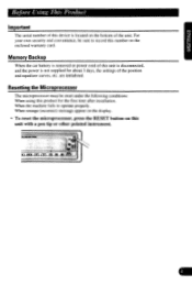
... display. • To reset the microprocessor, press the RESET button on this product for about 3 days, the settings of the position and equalizer curves, etc. Resetting the Microprocessor The microprocessor must be sure to operate properly. When the machine fails to record this unit is disconnected, and... the power is not supplied for the first time after installation. MI WM MYMM Fxa inn 1-1 d55 Memory Backup When the car battery is removed or power cord of this number on the bottom...
... display. • To reset the microprocessor, press the RESET button on this product for about 3 days, the settings of the position and equalizer curves, etc. Resetting the Microprocessor The microprocessor must be sure to operate properly. When the machine fails to record this unit is disconnected, and... the power is not supplied for the first time after installation. MI WM MYMM Fxa inn 1-1 d55 Memory Backup When the car battery is removed or power cord of this number on the bottom...
Operation Manual
Page 30
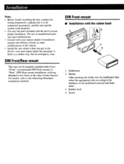
... stop. DIN Front-mount ■ Installation with the unit to ensure proper installation. Dashboard 2. Rubber bush 4. The use of unauthorized parts can be properly installed either from "Front" (conventional DIN Front-mount) or "Rear" (DIN Rear-mount installation, utilizing threaded screw holes at the...After inserting the holder into the dashboard, then select the appropriate tabs according to the following illustrated installation methods. Screw Installation Note: • Before finally installing the unit, connect the wiring temporarily, making sure it does not get in the driver's way ...
... stop. DIN Front-mount ■ Installation with the unit to ensure proper installation. Dashboard 2. Rubber bush 4. The use of unauthorized parts can be properly installed either from "Front" (conventional DIN Front-mount) or "Rear" (DIN Rear-mount installation, utilizing threaded screw holes at the...After inserting the holder into the dashboard, then select the appropriate tabs according to the following illustrated installation methods. Screw Installation Note: • Before finally installing the unit, connect the wiring temporarily, making sure it does not get in the driver's way ...
Operation Manual
Page 31
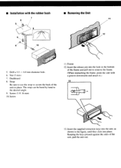
... 7 11 12 0 0 10 5. Insert the supplied extraction keys into the unit, as shown in the figure, until they click into the hole in place. ■ Installation with a groove downwards and attach it.) 13 13. Insert the release pin into place. Dashboard 8. Strap Be sure to use the strap to the desired...
... 7 11 12 0 0 10 5. Insert the supplied extraction keys into the unit, as shown in the figure, until they click into the hole in place. ■ Installation with a groove downwards and attach it.) 13 13. Insert the release pin into place. Dashboard 8. Strap Be sure to use the strap to the desired...
Operation Manual
Page 32
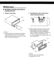
Factory radio mounting bracket 19. Use either truss screws (5 x 8 mm) or flush surface screws (5 x 9 mm), depending on each side. Frame 15. DIN Rear-mount ■ Installation using the screw holes on the side of the screw holes in the bottom of the head unit become aligned (are fitted), and tighten the ...
Factory radio mounting bracket 19. Use either truss screws (5 x 8 mm) or flush surface screws (5 x 9 mm), depending on each side. Frame 15. DIN Rear-mount ■ Installation using the screw holes on the side of the screw holes in the bottom of the head unit become aligned (are fitted), and tighten the ...

Operation Manual
Page 33
Otherwise, the effects of the sound field control cannot be sure to e disconnect the battery cable before beginning installation. • Refer to the owner's manual for vehicles with cable clamps or adhesive tape. Do not route wiring in the electrical system, be obtained. If .... Connecting the Units Note: • This unit is for details on the fuse holder. • When the 2 speaker system is a danger of this unit. Before installing it should. • Never feed power to the battery.
Otherwise, the effects of the sound field control cannot be sure to e disconnect the battery cable before beginning installation. • Refer to the owner's manual for vehicles with cable clamps or adhesive tape. Do not route wiring in the electrical system, be obtained. If .... Connecting the Units Note: • This unit is for details on the fuse holder. • When the 2 speaker system is a danger of this unit. Before installing it should. • Never feed power to the battery.

Operation Manual
Page 36
... CUSTOMER SERVICE DEPARTMENT PIONEER ELECTRONICS OF CANADA INC. 7405 THANS.CANADIENNE STE 3:32 VILLE Si 'T PO. Pioneer Eiectrorius (USA) Inc_ (PAL and Pioneer Eiectrorus Of Canada. and by tne use ' attached antennas. that tail to a nnuracturing detect when installed ano operated accordino ro.... Carefully package tne proauct using adequate oadoing - your car speaker require service. ONLY Should your name. CUSTOMER SERVICE DEPARTMENT PIONEER ELECTRONICS SERVICE. !NC P O BOX 1760 LONG BEACH. FOR PRODUCT INFORMATION OR TO LOCATE AN AUTHORIZED SERVICE COMPANY CALL:...
... CUSTOMER SERVICE DEPARTMENT PIONEER ELECTRONICS OF CANADA INC. 7405 THANS.CANADIENNE STE 3:32 VILLE Si 'T PO. Pioneer Eiectrorius (USA) Inc_ (PAL and Pioneer Eiectrorus Of Canada. and by tne use ' attached antennas. that tail to a nnuracturing detect when installed ano operated accordino ro.... Carefully package tne proauct using adequate oadoing - your car speaker require service. ONLY Should your name. CUSTOMER SERVICE DEPARTMENT PIONEER ELECTRONICS SERVICE. !NC P O BOX 1760 LONG BEACH. FOR PRODUCT INFORMATION OR TO LOCATE AN AUTHORIZED SERVICE COMPANY CALL:...
