Operation Manual
Page 2
... Nuance Control 19 4 15-Band Graphic Equalizer Adjustment 20 Storing Equalizer Curves 22 4 Flat Curve Function 22 4 4 5 Sub-woofer Setting Adjustment 23 6 Sub-woofer Output 23 7 Sub-woofer Setting Adjustment 23 Basic Operation 8 Other Functions 25 Adjusting the Volume 8 Setting the Dimmer 25 Volume Attenuator 8 Changing the Spectrum Analyzer Display 9 Specifications 26 Reproducing a Realistic Sound Field...
... Nuance Control 19 4 15-Band Graphic Equalizer Adjustment 20 Storing Equalizer Curves 22 4 Flat Curve Function 22 4 4 5 Sub-woofer Setting Adjustment 23 6 Sub-woofer Output 23 7 Sub-woofer Setting Adjustment 23 Basic Operation 8 Other Functions 25 Adjusting the Volume 8 Setting the Dimmer 25 Volume Attenuator 8 Changing the Spectrum Analyzer Display 9 Specifications 26 Reproducing a Realistic Sound Field...
Operation Manual
Page 5
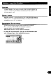
Before Using This Product Important The serial number of this device is located on the bottom of the position and equalizer curves, etc. When the machine fails to record this number...inn 1-1 d55 For your own security and convenience, be reset under the following conditions: When using this product for about 3 days, the settings of the unit. Resetting the Microprocessor The microprocessor must be sure to operate properly. are ... the RESET button on the enclosed warranty card. Memory Backup When the car battery is not supplied for the first time after installation.
Before Using This Product Important The serial number of this device is located on the bottom of the position and equalizer curves, etc. When the machine fails to record this number...inn 1-1 d55 For your own security and convenience, be reset under the following conditions: When using this product for about 3 days, the settings of the unit. Resetting the Microprocessor The microprocessor must be sure to operate properly. are ... the RESET button on the enclosed warranty card. Memory Backup When the car battery is not supplied for the first time after installation.
Operation Manual
Page 6
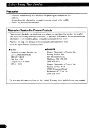
...information is not available, please contact the companies listed below for repair without advance contact. ■ U.S.A. CA 90801 800-421-1404 ■ CANADA Pioneer Electronics of Canada. Inc. Factory Service West 13911 Bridgeport Road Richmond, BC V6V 1J6 (604) 278-...aftersales service (including warranty conditions) or any other information. Pioneer Electronics Service, Inc. Factory Service East 300 Allstate Parkway Markham, ON L3R 0P2 (905) 479-441 I Pioneer Electronics of Canada. Inc. Box 1760 Long Beach. Before Using This Product Precaution • Keep this manual handy...
...information is not available, please contact the companies listed below for repair without advance contact. ■ U.S.A. CA 90801 800-421-1404 ■ CANADA Pioneer Electronics of Canada. Inc. Factory Service West 13911 Bridgeport Road Richmond, BC V6V 1J6 (604) 278-...aftersales service (including warranty conditions) or any other information. Pioneer Electronics Service, Inc. Factory Service East 300 Allstate Parkway Markham, ON L3R 0P2 (905) 479-441 I Pioneer Electronics of Canada. Inc. Box 1760 Long Beach. Before Using This Product Precaution • Keep this manual handy...
Operation Manual
Page 7
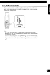
... Controller When using the remote controller supplied with the +/- buttons and the ATT button operate this unit directly and do not operate the head unit. (The volume level ... in the Programmable button can be operated with the Programmable button in the head unit.) button in the head unit.) • You can recall equalizer curves with the PGM button, but you must set the remote controller switch to the DSP position. 0 Z' • Lgc Cl) O t • ca t ■ Note: • The + and...
... Controller When using the remote controller supplied with the +/- buttons and the ATT button operate this unit directly and do not operate the head unit. (The volume level ... in the Programmable button can be operated with the Programmable button in the head unit.) button in the head unit.) • You can recall equalizer curves with the PGM button, but you must set the remote controller switch to the DSP position. 0 Z' • Lgc Cl) O t • ca t ■ Note: • The + and...
Operation Manual
Page 8
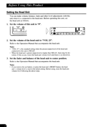
... • "VOL 23" is the standard setting when the preout output level of this unit to "0". 0 la S Air En la u p to the Operation Manual that accompanies the head unit. k Itkka Mk Mt Mk ma,cy 2. Note: • If you remove the car battery, or press the head unit's RESET button... may be dis- Refer to the head unit. tortion. Before Using This Product Setting the Head Unit You can make volume, balance, fader and other level adjustments with this unit when it is connected to the Operation Manual that accompanies the head unit. Before operating this occurs, lower the...
... • "VOL 23" is the standard setting when the preout output level of this unit to "0". 0 la S Air En la u p to the Operation Manual that accompanies the head unit. k Itkka Mk Mt Mk ma,cy 2. Note: • If you remove the car battery, or press the head unit's RESET button... may be dis- Refer to the head unit. tortion. Before Using This Product Setting the Head Unit You can make volume, balance, fader and other level adjustments with this unit when it is connected to the Operation Manual that accompanies the head unit. Before operating this occurs, lower the...

Operation Manual
Page 10
...the Spectrum Analyzer Display This unit offers 7 display types you cannot switch to the Sub-woofer Display. • When the audio signal is set to OFF. Cal nl NUM NI IN NI IMI Ico _Deo, nn an v.. Peak Bound Display Each press of the D button changes the....41. 11= u Ill in the following order: Peak Bound Display -o Peak Display -0 Simple Level Display -*Symmetric Display -o Radial Display -o Sub-woofer Display -0 Graphic Equalizer Display Note: • When sub-woofer output is not input for more than 30 seconds, the display automat- you can easily switch between. • Change...
...the Spectrum Analyzer Display This unit offers 7 display types you cannot switch to the Sub-woofer Display. • When the audio signal is set to OFF. Cal nl NUM NI IN NI IMI Ico _Deo, nn an v.. Peak Bound Display Each press of the D button changes the....41. 11= u Ill in the following order: Peak Bound Display -o Peak Display -0 Simple Level Display -*Symmetric Display -o Radial Display -o Sub-woofer Display -0 Graphic Equalizer Display Note: • When sub-woofer output is not input for more than 30 seconds, the display automat- you can easily switch between. • Change...
Operation Manual
Page 11
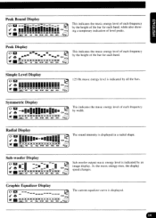
... of each frequency by all the bars. aDUD = PDS as non II I DI In Ir Mt an in a radial shape. DIM DIM WM The current equalizer curve is displayed in no = au ND OW MD DOD DM This indicates the music energy level of each band. NI Pi was ams KIM... Iti DO In NI IN 1.1k ID PP IP 'IN DP fralms vs ma maw am Mt 1O:TV. Peak Bound Display ojr • (a. Graphic Equalizer Display WI DO PO UM DI III DP DI Ilt k L. This indicates the music energy level of level peaks.
... of each frequency by all the bars. aDUD = PDS as non II I DI In Ir Mt an in a radial shape. DIM DIM WM The current equalizer curve is displayed in no = au ND OW MD DOD DM This indicates the music energy level of each band. NI Pi was ams KIM... Iti DO In NI IN 1.1k ID PP IP 'IN DP fralms vs ma maw am Mt 1O:TV. Peak Bound Display ojr • (a. Graphic Equalizer Display WI DO PO UM DI III DP DI Ilt k L. This indicates the music energy level of level peaks.
Operation Manual
Page 12
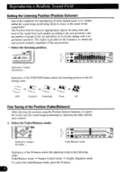
... Astm i.... PI /4 (al ED {Ill k N IN Ai ON IN lit a in the car and allows to recall this setting with a single button operation. Each press of the POSITION button selects the listening position in the following ... the M button selects the adjusting mode in the following order: Fader/Balance mode Nuance Control mode Graphic Equalizer mode To cancel the Fader/Balance mode, press the D button. MIN CR,,i n MI e1.! ... the center of the Position (Fader/Balance) After choosing the position using the Position Selector function, it is possible to fine tune the sound image positioning by adjusting...
... Astm i.... PI /4 (al ED {Ill k N IN Ai ON IN lit a in the car and allows to recall this setting with a single button operation. Each press of the POSITION button selects the listening position in the following ... the M button selects the adjusting mode in the following order: Fader/Balance mode Nuance Control mode Graphic Equalizer mode To cancel the Fader/Balance mode, press the D button. MIN CR,,i n MI e1.! ... the center of the Position (Fader/Balance) After choosing the position using the Position Selector function, it is possible to fine tune the sound image positioning by adjusting...
Operation Manual
Page 17
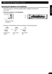
a II IN N N I I I III tnIMOIN .:1 S. : , a I weN 4- -.-;Le Each press of the FR button selects the speakers in the following order: 4_ 45-1(R:-."--V--j ,--r-•-...F..-_..,.,, R .--...F.._ ,......: -'-' i.L R .2./ Both front/rear speakers Front speakers only Rear speakers only Each press changes the speakers ... '"lIe. Adjusting the Equalizer Curve Selecting the Speakers to be Equalized Select the speakers to which the equalizer effect is applied, from the front, rear or both. • Select the speakers to be Equalized.
a II IN N N I I I III tnIMOIN .:1 S. : , a I weN 4- -.-;Le Each press of the FR button selects the speakers in the following order: 4_ 45-1(R:-."--V--j ,--r-•-...F..-_..,.,, R .--...F.._ ,......: -'-' i.L R .2./ Both front/rear speakers Front speakers only Rear speakers only Each press changes the speakers ... '"lIe. Adjusting the Equalizer Curve Selecting the Speakers to be Equalized Select the speakers to which the equalizer effect is applied, from the front, rear or both. • Select the speakers to be Equalized.
Operation Manual
Page 18
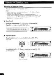
... preset under that button. F5 or Ul - MN NM en • Sequential Recall • Recall equalizer curves memorized in buttons U I - U3 (user's curves). jrn (7'n r.7) ru-r) 05-1 o 6 EN, LN_SID nes M ae •IN SY Mk AU NrAl N,. U3 to "Factory Preset ... • Press one of the buttons Fl - Note: • Factory Preset Curves are two ways to "Storing Equalizer Curves.' F5 (factory preset curves) and Ul - F5 or Ul - U3. on the next page.) • Equalizer curves adjusted by the user arc memorized in buttons Fl - on page 22 for 2 seconds (0 1. 6 MN. ...
... preset under that button. F5 or Ul - MN NM en • Sequential Recall • Recall equalizer curves memorized in buttons U I - U3 (user's curves). jrn (7'n r.7) ru-r) 05-1 o 6 EN, LN_SID nes M ae •IN SY Mk AU NrAl N,. U3 to "Factory Preset ... • Press one of the buttons Fl - Note: • Factory Preset Curves are two ways to "Storing Equalizer Curves.' F5 (factory preset curves) and Ul - F5 or Ul - U3. on the next page.) • Equalizer curves adjusted by the user arc memorized in buttons Fl - on page 22 for 2 seconds (0 1. 6 MN. ...
Operation Manual
Page 20
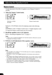
... time the factory curve or user's curve is recalled, the equalizer curve after nuance control will be recalled. • After selecting...page 17. Adjusting the Equalizer Curve Nuance Control Overall adjustment of the effect of the equalizer curve. Perform overall adjustment of equalizer curve (Nuance Control) is...mode in which no equalizer curve has been preset (= flat curve) can be adjusted. Nuance Control mode Graphic Equalizer mode To cancel the...to spectrum analyzer indications. Recall the equalizer curve to "Recalling an Equalizer Curve" on the equalizer curve you do not perform an...
... time the factory curve or user's curve is recalled, the equalizer curve after nuance control will be recalled. • After selecting...page 17. Adjusting the Equalizer Curve Nuance Control Overall adjustment of the effect of the equalizer curve. Perform overall adjustment of equalizer curve (Nuance Control) is...mode in which no equalizer curve has been preset (= flat curve) can be adjusted. Nuance Control mode Graphic Equalizer mode To cancel the...to spectrum analyzer indications. Recall the equalizer curve to "Recalling an Equalizer Curve" on the equalizer curve you do not perform an...
Operation Manual
Page 21
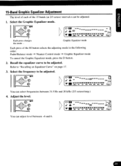
... on page 17. 3. Adjust the level. -2 ".* Fit,' ant am Mk VD .pp MI ISM NM You can select frequencies between -6 and 6. Graphic Equalizer mode Each press of the 15 bands (at 2/3 octave intervals) can be adjusted. 1. kr'," Each press changes the mode ... cif - '1": El rpp~PM...step.) 4. e GCP1 0 ea C> AP EMI mg CM Li lk non= ow lit k KILN it WI AWL MOM NW kik OM --- e PI t t - - 15-Band Graphic Equalizer Adjustment The level of each of the M button selects the adjusting mode in the following order: Fader/Balance mode -• Nuance Control mode -• Graphic...
... on page 17. 3. Adjust the level. -2 ".* Fit,' ant am Mk VD .pp MI ISM NM You can select frequencies between -6 and 6. Graphic Equalizer mode Each press of the 15 bands (at 2/3 octave intervals) can be adjusted. 1. kr'," Each press changes the mode ... cif - '1": El rpp~PM...step.) 4. e GCP1 0 ea C> AP EMI mg CM Li lk non= ow lit k KILN it WI AWL MOM NW kik OM --- e PI t t - - 15-Band Graphic Equalizer Adjustment The level of each of the M button selects the adjusting mode in the following order: Fader/Balance mode -• Nuance Control mode -• Graphic...

Operation Manual
Page 22
Refer to spectrum analyzer indications. If you want to retain the adjusted curve, store it in memory. Adjusting the Equalizer Curve 5. Store the adjusted equalizer curve in the memory of this unit. • After selecting the Graphic Equalizer mode, if you do not perform an operation within about 25 seconds, the Graphic Equalizer mode is recalled. Note: • The adjusted equalizer curve will be reset when another equalizer curve is canceled, and the display returns to "Storing Equalizer Curves" on the next page.
Refer to spectrum analyzer indications. If you want to retain the adjusted curve, store it in memory. Adjusting the Equalizer Curve 5. Store the adjusted equalizer curve in the memory of this unit. • After selecting the Graphic Equalizer mode, if you do not perform an operation within about 25 seconds, the Graphic Equalizer mode is recalled. Note: • The adjusted equalizer curve will be reset when another equalizer curve is canceled, and the display returns to "Storing Equalizer Curves" on the next page.
Operation Manual
Page 23
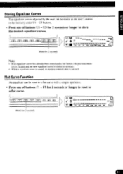
... Storing Equalizer Curves The equalizer curves adjusted by the user can be stored as the user's curves in memory. • When a equalizer curve is stored, its nuance control value is stored in the memory under the button, the previous mem- ory is cleared and the new equalizer curve is set to... 0. Flat Curve Function An equalizer can be reset to a flat curve. fl it Cln FTI - 1rf fTn-1 n ri"-)I Hold for 2 seconds Note:...
... Storing Equalizer Curves The equalizer curves adjusted by the user can be stored as the user's curves in memory. • When a equalizer curve is stored, its nuance control value is stored in the memory under the button, the previous mem- ory is cleared and the new equalizer curve is set to... 0. Flat Curve Function An equalizer can be reset to a flat curve. fl it Cln FTI - 1rf fTn-1 n ri"-)I Hold for 2 seconds Note:...
Operation Manual
Page 26
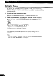
...pressing this unit's M and U2 buttons, press the head unit's SOURCE button to the Operation Manual that accompanies the head unit. 2. Switch the head unit source OFF. Note: • The initial setting for the dimmer is ON (the display is automatically dimmed when you switch on your vehicle's ...headlights. Other Functions Setting the Dimmer To prevent the display becoming too bright at night, it is automatically ...
...pressing this unit's M and U2 buttons, press the head unit's SOURCE button to the Operation Manual that accompanies the head unit. 2. Switch the head unit source OFF. Note: • The initial setting for the dimmer is ON (the display is automatically dimmed when you switch on your vehicle's ...headlights. Other Functions Setting the Dimmer To prevent the display becoming too bright at night, it is automatically ...

Operation Manual
Page 29
DEQ-7600 CD PIONEER The Art of Entertainment Printed in Japan Imprime au Japon
DEQ-7600 CD PIONEER The Art of Entertainment Printed in Japan Imprime au Japon
Operation Manual
Page 30
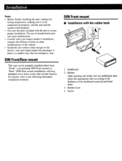
... an emergency stop. Dashboard 2. Installation Note: • Before finally installing the unit, connect the wiring temporarily, making sure it does not get in the driver's way and cannot injure the passenger if there is all connected up properly, and the unit and the system work properly. • Use only the parts included with the rubber bush...
... an emergency stop. Dashboard 2. Installation Note: • Before finally installing the unit, connect the wiring temporarily, making sure it does not get in the driver's way and cannot injure the passenger if there is all connected up properly, and the unit and the system work properly. • Use only the parts included with the rubber bush...
Operation Manual
Page 31
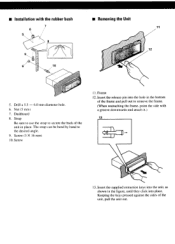
Screw (5 X 16 mm) 10. Dashboard 8. Strap Be sure to use the strap to secure the back of the frame and pull out to the desired anele. 9. The strap can be bend by hand to remove ...; Removing the Unit 7 11 12 0 0 10 5. Nut (5 mm) 7. Keeping the keys pressed against the sides of the unit, pull the unit out. Screw 11. ■ Installation with a groove downwards and attach it.) 13 13. Insert the supplied extraction keys into place. Frame 12. Drill a 5.5 - 6.0 mm diameter hole. 6.
Screw (5 X 16 mm) 10. Dashboard 8. Strap Be sure to use the strap to secure the back of the frame and pull out to the desired anele. 9. The strap can be bend by hand to remove ...; Removing the Unit 7 11 12 0 0 10 5. Nut (5 mm) 7. Keeping the keys pressed against the sides of the unit, pull the unit out. Screw 11. ■ Installation with a groove downwards and attach it.) 13 13. Insert the supplied extraction keys into place. Frame 12. Drill a 5.5 - 6.0 mm diameter hole. 6.

Operation Manual
Page 33
... seat rails. Do not route wiring in the electrical system, be sure to e disconnect the battery cable before beginning installation. • Refer to work ...manual for vehicles with cable clamps or adhesive tape. This will be exceeded, causing overheating. • When replacing fuse, be obtained. To protect the wiring, wrap adhesive tape around them where they lie against metal parts. • Route and secure all wiring...8226; Secure the wiring with a 12-volt battery and negative grounding. Connecting the Units Note: • This unit is employed, use the front outputs of...
... seat rails. Do not route wiring in the electrical system, be sure to e disconnect the battery cable before beginning installation. • Refer to work ...manual for vehicles with cable clamps or adhesive tape. This will be exceeded, causing overheating. • When replacing fuse, be obtained. To protect the wiring, wrap adhesive tape around them where they lie against metal parts. • Route and secure all wiring...8226; Secure the wiring with a 12-volt battery and negative grounding. Connecting the Units Note: • This unit is employed, use the front outputs of...
Operation Manual
Page 36
...period wne:tier possession o- return defective car speaker to function or-Peery under the conditions set torth anove. or any 0'0CJCI ...using adequate oadoing - PIONEER The Art of unautnonzed parts or iabor. Pioneer Eiectrorius (USA) Inc_ (PAL and Pioneer Eiectrorus Of Canada. irc. and by tne use Or oatteres not conforming to a nnuracturing detect when installed ano operated accordino ro the owners instructions.... THIS WARRANTY GIVES YOU SPECIFIC LEGAL RIGHTS. WARRANTIES. APPLICABLE TO THIS PRODUCT TO OBTAIN SERVICE CAR STEREO PRODUCTS (EXCEPT CAR SPEAKERS SOLD IN THE ...
...period wne:tier possession o- return defective car speaker to function or-Peery under the conditions set torth anove. or any 0'0CJCI ...using adequate oadoing - PIONEER The Art of unautnonzed parts or iabor. Pioneer Eiectrorius (USA) Inc_ (PAL and Pioneer Eiectrorus Of Canada. irc. and by tne use Or oatteres not conforming to a nnuracturing detect when installed ano operated accordino ro the owners instructions.... THIS WARRANTY GIVES YOU SPECIFIC LEGAL RIGHTS. WARRANTIES. APPLICABLE TO THIS PRODUCT TO OBTAIN SERVICE CAR STEREO PRODUCTS (EXCEPT CAR SPEAKERS SOLD IN THE ...


