
Other Manual
Page 1
... shift, handbrake and seat rails. Le code de couleur des câbles utilisé pour ce produit est conforme à CEMA. INSTALLATION MANUAL OF OF DEH-P7300 DEH-P6300 This product conforms to an external power amp's system remote control or the car's Auto-antenna relay control terminal (max. 300 mA 12 V DC).
... shift, handbrake and seat rails. Le code de couleur des câbles utilisé pour ce produit est conforme à CEMA. INSTALLATION MANUAL OF OF DEH-P7300 DEH-P6300 This product conforms to an external power amp's system remote control or the car's Auto-antenna relay control terminal (max. 300 mA 12 V DC).
Other Manual
Page 2
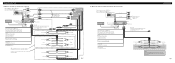
...with power regardless of ignition switch position. Red To electric terminal controlled by ignition switch (12 V DC) ON/OFF. Use this for DEH-P7300) If you use a cellular telephone, connect it via the Audio Mute lead on the cellular telephone. Orange/white To lightnig switch terminal..... Black (ground) To vehicle (metal) body. Refer to the Operation Manual). Front output This RCA pin jack is available only for DEH-P7300) If you have the separately available amplifier. If not, keep the Audio Mute lead free of any connections. Connecting the Units 7 When...
...with power regardless of ignition switch position. Red To electric terminal controlled by ignition switch (12 V DC) ON/OFF. Use this for DEH-P7300) If you use a cellular telephone, connect it via the Audio Mute lead on the cellular telephone. Orange/white To lightnig switch terminal..... Black (ground) To vehicle (metal) body. Refer to the Operation Manual). Front output This RCA pin jack is available only for DEH-P7300) If you have the separately available amplifier. If not, keep the Audio Mute lead free of any connections. Connecting the Units 7 When...
Other Manual
Page 3
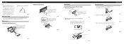
For details, refer to this unit. 1. DIN Front-mount Installation with a groove downwards and attach it.) 2. Fastening the unit to the factory radio mounting bracket. (Fig. 9) (Fig. 10) Select a position where the screw holes of the bracket and the screw holes of the head unit become aligned (are fitted), and tighten the screws at the sides of unit chassis). Fig. 8 Factory radio mounting bracket Fig. 9 Screw Dashboard or Console Fig. 10 Fixing the Front Panel If you do not operate the Detaching and Replacing the Front Panel Function, use of unauthorized parts can be damaged if it...
For details, refer to this unit. 1. DIN Front-mount Installation with a groove downwards and attach it.) 2. Fastening the unit to the factory radio mounting bracket. (Fig. 9) (Fig. 10) Select a position where the screw holes of the bracket and the screw holes of the head unit become aligned (are fitted), and tighten the screws at the sides of unit chassis). Fig. 8 Factory radio mounting bracket Fig. 9 Screw Dashboard or Console Fig. 10 Fixing the Front Panel If you do not operate the Detaching and Replacing the Front Panel Function, use of unauthorized parts can be damaged if it...