Owners Manual
Page 8
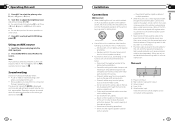
...impedance value). ! This unit 1 2 34 5 1 Power cord input 2 Rear output or subwoofer output 3 Antenna input 4 Fuse (10 A) 5 Wired remote input Hard-wired remote control adaptor can also perform the same operation on other colors. 7 Press M.C. R (red)-G (green)-B (blue) 6 Turn M.C. A call is turned on .... - Also, never connect it to the power terminal of this unit 5 Press M.C. Place all cables away from a connected Pioneer navigation unit. Do not shorten any disconnected cable connectors with a glass antenna, connect it to the antenna booster power supply terminal....
...impedance value). ! This unit 1 2 34 5 1 Power cord input 2 Rear output or subwoofer output 3 Antenna input 4 Fuse (10 A) 5 Wired remote input Hard-wired remote control adaptor can also perform the same operation on other colors. 7 Press M.C. R (red)-G (green)-B (blue) 6 Turn M.C. A call is turned on .... - Also, never connect it to the power terminal of this unit 5 Press M.C. Place all cables away from a connected Pioneer navigation unit. Do not shorten any disconnected cable connectors with a glass antenna, connect it to the antenna booster power supply terminal....
Owners Manual
Page 9
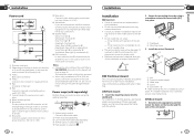
... different. b Blue/white Connect to the green and green/black leads. When using the optional amplifier. 1 3 2 4 5 5 1 System remote control Connect to system control terminal of the power amp (max. 300 mA 12 V DC). Do not connect anything to auto-antenna relay... 6 to 3. 3 Yellow Back-up (or accessory) 4 Yellow Connect to the constant 12 V supply terminal. 5 Red Accessory (or back-up) 6 Red Connect to terminal controlled by using either front-mount or rear-mount installation. In this may be properly installed using a screwdriver to SW...
... different. b Blue/white Connect to the green and green/black leads. When using the optional amplifier. 1 3 2 4 5 5 1 System remote control Connect to system control terminal of the power amp (max. 300 mA 12 V DC). Do not connect anything to auto-antenna relay... 6 to 3. 3 Yellow Back-up (or accessory) 4 Yellow Connect to the constant 12 V supply terminal. 5 Red Accessory (or back-up) 6 Red Connect to terminal controlled by using either front-mount or rear-mount installation. In this may be properly installed using a screwdriver to SW...


