WJSX150 User Guide
Page 1
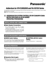
... their passwords. (Refer to p. 2 Operation Start (Auto Login).) This operation is skipped when the auto login is set to ON. (Refer to the operating instructions of this switch to 40. To operate in this document are applicable when WJ-SX150A Administrator Console and the firmware of matrix switcher.) 1. The OPERATE indicator will light up and "Terminal Mode No User" appears on the power of matrix switcher . • To connect System Controller WV...
... their passwords. (Refer to p. 2 Operation Start (Auto Login).) This operation is skipped when the auto login is set to ON. (Refer to the operating instructions of this switch to 40. To operate in this document are applicable when WJ-SX150A Administrator Console and the firmware of matrix switcher.) 1. The OPERATE indicator will light up and "Terminal Mode No User" appears on the power of matrix switcher . • To connect System Controller WV...

WJSX150 User Guide
Page 2
... blink on the LCD. User ID Password 150 _____ Note: The factory default setting is set to the operating instructions of the system, press the MON LOCK/LOGOUT button while holding down the SHIFT button. Note: If you want to save the power consumption, disconnect the DC 9 V plug from the controller, and remove the AC adapter from the AC outlet. ■ Operation End (Auto Logout) If the auto logout is set...
... blink on the LCD. User ID Password 150 _____ Note: The factory default setting is set to the operating instructions of the system, press the MON LOCK/LOGOUT button while holding down the SHIFT button. Note: If you want to save the power consumption, disconnect the DC 9 V plug from the controller, and remove the AC adapter from the AC outlet. ■ Operation End (Auto Logout) If the auto logout is set...
WJSX150 User Guide
Page 3
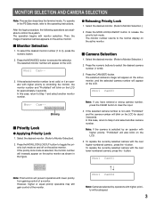
... Selection.) 2. To select the desired monitor number (1 to clear the input. 4. Press the CAM (SET) button. To replace the currently selected camera with the next higher-numbered camera , press the + button. The operation begins with lower priority from gaining control of selected camera appears on the LCD for approximately 3 seconds. If the priority lock mode is selected by operators with higher priority, "Prohibited" will appear...
... Selection.) 2. To select the desired monitor number (1 to clear the input. 4. Press the CAM (SET) button. To replace the currently selected camera with the next higher-numbered camera , press the + button. The operation begins with lower priority from gaining control of selected camera appears on the LCD for approximately 3 seconds. If the priority lock mode is selected by operators with higher priority, "Prohibited" will appear...
WJSX150 User Guide
Page 14
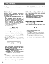
... mode. All the video output signals are associated with the same-numbered camera input connectors. Select a monitor which displays "ALARM". 2. Operate camera with an alarm input will become operable. 3. In the factory default setting, the alarm inputs 1 to 16 are sent to the same monitor. • Sequence mode: An alarm operation is replaced by another one after the dwell time ends. • Hold mode: An initial alarm operation is continued even after another monitor, "ACK" will be automatically reset...
... mode. All the video output signals are associated with the same-numbered camera input connectors. Select a monitor which displays "ALARM". 2. Operate camera with an alarm input will become operable. 3. In the factory default setting, the alarm inputs 1 to 16 are sent to the same monitor. • Sequence mode: An alarm operation is replaced by another one after the dwell time ends. • Hold mode: An initial alarm operation is continued even after another monitor, "ACK" will be automatically reset...

WJSX150 User Guide
Page 18
.... 3D joystick rightward (B): Moves the cursor to the normal view, press the F2 button while SETUP MENU is installed in SETUP MENU. 18 System Setup 501 5On Off 6. To end the setting and return to the right. 7. button: Decrements a parameter. WJ-HD500 SERIES CONTROL (TERMINAL MODE) Matrix switcher can neither connect nor control a WJHD500 Series recorder. Enter the recorder mode. (Refer to p. 3 Monitor Selection.) 3. The following functions of WJ...
.... 3D joystick rightward (B): Moves the cursor to the normal view, press the F2 button while SETUP MENU is installed in SETUP MENU. 18 System Setup 501 5On Off 6. To end the setting and return to the right. 7. button: Decrements a parameter. WJ-HD500 SERIES CONTROL (TERMINAL MODE) Matrix switcher can neither connect nor control a WJHD500 Series recorder. Enter the recorder mode. (Refer to p. 3 Monitor Selection.) 3. The following functions of WJ...
WJSX150 User Guide
Page 20
.../PAUSE button. Record List will be adjusted by "REC ONLY" setting of 430 CAMERA/440 ALARM PORT/450 SERIAL PORT/460 MUX MOTION DET in SETUP MENU or the Alarm Mode window in WJ-SX150A Administrator Console. (Refer to WJ-HD500 Series Operating Instructions for details and other recording modes. ● Stopping REC ONLY Alarm Recording You can be searched for through the date and time. 1. The digital disk recorder will start recording, press the REC button. Note...
.../PAUSE button. Record List will be adjusted by "REC ONLY" setting of 430 CAMERA/440 ALARM PORT/450 SERIAL PORT/460 MUX MOTION DET in SETUP MENU or the Alarm Mode window in WJ-SX150A Administrator Console. (Refer to WJ-HD500 Series Operating Instructions for details and other recording modes. ● Stopping REC ONLY Alarm Recording You can be searched for through the date and time. 1. The digital disk recorder will start recording, press the REC button. Note...

WJSX150 User Guide
Page 22
... a parameter. To end the setting and return to p. 19.) Note: The multiscreen segment patterns can be switched as WJ-HD500 Series. (Refer to the normal view, press the F2 button when SETUP MENU is correctly and securely connected. 2. Press the MENU button repeatedly until "System Setup" appears on the LCD. The following is installed in SETUP MENU. 22 ● Recorder Mode The operations are the same as...
... a parameter. To end the setting and return to p. 19.) Note: The multiscreen segment patterns can be switched as WJ-HD500 Series. (Refer to the normal view, press the F2 button when SETUP MENU is correctly and securely connected. 2. Press the MENU button repeatedly until "System Setup" appears on the LCD. The following is installed in SETUP MENU. 22 ● Recorder Mode The operations are the same as...

WJSX150 User Guide
Page 25
Searching filter windows Available controls and functions (TIME&DATE FILTERING window) ■ TIME&DATE FILTERING START JAN . 1 . 03 END JAN . 1 . 03 00 : 00 AM 0 : 00 AM SET : [SET] CANCEL : [ESC] JogDial clockwise: Increments a parameter. Available controls and functions (CAMERA FILTERING window) CAMERA FILTERING CAMERA 1 2345678 9 10 11 12 13 14 15 16 SET : [ SET ] CANCEL : [ ESC ] JogDial clockwise or counterclockwise: Changes the camera number, pointed by performing one of the...
Searching filter windows Available controls and functions (TIME&DATE FILTERING window) ■ TIME&DATE FILTERING START JAN . 1 . 03 END JAN . 1 . 03 00 : 00 AM 0 : 00 AM SET : [SET] CANCEL : [ESC] JogDial clockwise: Increments a parameter. Available controls and functions (CAMERA FILTERING window) CAMERA FILTERING CAMERA 1 2345678 9 10 11 12 13 14 15 16 SET : [ SET ] CANCEL : [ ESC ] JogDial clockwise or counterclockwise: Changes the camera number, pointed by performing one of the...

WJSX150 User Guide
Page 26
.... - The motion detection area setup window will be searched by the date and time when a camera detected the brightness-level change. Move the "+" mark to a desired area with the 3D joystick, and then press the CAM (SET) button again. • VMD search Recording events will be displayed. Press the CAM (SET) button. Enter a camera number and time range. Press the CAM (SET) button. The start point of motion detection area...
.... - The motion detection area setup window will be searched by the date and time when a camera detected the brightness-level change. Move the "+" mark to a desired area with the 3D joystick, and then press the CAM (SET) button again. • VMD search Recording events will be displayed. Press the CAM (SET) button. Enter a camera number and time range. Press the CAM (SET) button. The start point of motion detection area...

WJSX150 User Guide
Page 30
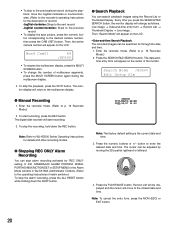
... Alarm Recording The operations are the same as WJ-HD500 Series. (Refer to p. 20.) ● Search Playback You can search playback images using a PS·Data system controller, refer to p. 19.) Note: 4C-, 4D-, 7-, 10-, 13- Note: Refer to the operating instructions of WJ-HD200 Series via system controller. Press the SEARCH/T&D SEARCH button. You need to remove the board from the matrix switcher. ■ Displaying WJ-HD200 Series SETUP MENU...
... Alarm Recording The operations are the same as WJ-HD500 Series. (Refer to p. 20.) ● Search Playback You can search playback images using a PS·Data system controller, refer to p. 19.) Note: 4C-, 4D-, 7-, 10-, 13- Note: Refer to the operating instructions of WJ-HD200 Series via system controller. Press the SEARCH/T&D SEARCH button. You need to remove the board from the matrix switcher. ■ Displaying WJ-HD200 Series SETUP MENU...
WJSX150 User Guide
Page 34
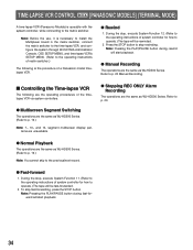
..., OSD SETUP MENU, and time-lapse VCR's SETUP MENU. (Refer to the operating instructions of matrix switcher.) The following are the operating procedures of system controller for how to operate.) The tape will start playback. ● Manual Recording The operations are the same as WJ-HD500 Series. During the stop fast-forwarding, press the STOP button. segment multiscreen display patterns are unavailable. ● Stopping REC ONLY Alarm Recording The operations are...
..., OSD SETUP MENU, and time-lapse VCR's SETUP MENU. (Refer to the operating instructions of matrix switcher.) The following are the operating procedures of system controller for how to operate.) The tape will start playback. ● Manual Recording The operations are the same as WJ-HD500 Series. During the stop fast-forwarding, press the STOP button. segment multiscreen display patterns are unavailable. ● Stopping REC ONLY Alarm Recording The operations are...
WJSX150 User Guide
Page 35
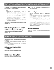
... Operating Instructions. 35 Press the PLAY/PAUSE button. Notes: • Before the use, it is necessary to install the Multiplexer board in the matrix switcher, connect the matrix switcher to the digital disk recorder, and configure the system through WJ-SX150A Administrator Console, OSD SETUP MENU, and time-lapse VCR's SETUP MENU. (Refer to the operating instructions of matrix switcher for how to the desired camera number, then press the CAM (SET) button...
... Operating Instructions. 35 Press the PLAY/PAUSE button. Notes: • Before the use, it is necessary to install the Multiplexer board in the matrix switcher, connect the matrix switcher to the digital disk recorder, and configure the system through WJ-SX150A Administrator Console, OSD SETUP MENU, and time-lapse VCR's SETUP MENU. (Refer to the operating instructions of matrix switcher for how to the desired camera number, then press the CAM (SET) button...

WJSX150 User Guide
Page 37
... the recorder's unit address is set to 1 through SETUP MENU or WJ-SX150A administrator Console. (Refer to this unit's operating instructions.) If another number is selected, you cannot control the recorder. • To control cameras at the front panel of recorder, connect the DATA 4 connector and the DATA port of recorder with a modular cable. (PS·Data system controller is Ver. 1.30 or later. • Only one recorder can be connected to the recorder's DATA port with a recorder to operate via...
... the recorder's unit address is set to 1 through SETUP MENU or WJ-SX150A administrator Console. (Refer to this unit's operating instructions.) If another number is selected, you cannot control the recorder. • To control cameras at the front panel of recorder, connect the DATA 4 connector and the DATA port of recorder with a modular cable. (PS·Data system controller is Ver. 1.30 or later. • Only one recorder can be connected to the recorder's DATA port with a recorder to operate via...

WJSX150 User Guide
Page 38
... connector to 16 connectors with a coaxial cable. 5. Select the recorder's new unit address, which is the description of the connection between a recorder and this unit's operating instructions.) • If the recorder's unit address, set in Step 1, and the recorder setting, set in Step 1, in 600 RECORDER of SETUP MENU or the Recorder window of WJ-SX150A Administrator Console. (Refer to this unit's operating instructions.) System controller (Terminal Mode) Monitor EXT IN MONITOR OUT ALARM DATA HDR DATA 4 TERM OFF ON SERIAL DATA 3 DATA 2 DATA 1 RS485(CAMERA...
... connector to 16 connectors with a coaxial cable. 5. Select the recorder's new unit address, which is the description of the connection between a recorder and this unit's operating instructions.) • If the recorder's unit address, set in Step 1, and the recorder setting, set in Step 1, in 600 RECORDER of SETUP MENU or the Recorder window of WJ-SX150A Administrator Console. (Refer to this unit's operating instructions.) System controller (Terminal Mode) Monitor EXT IN MONITOR OUT ALARM DATA HDR DATA 4 TERM OFF ON SERIAL DATA 3 DATA 2 DATA 1 RS485(CAMERA...

WJSX150 User Guide
Page 39
... 16 connectors to the recorder's VIDEO IN 1 to the recorder's DATA port with a coaxial cable. 4. Notes: • Select the PS·Data protocol for all cameras in SETUP MENU of the recorder. 3. Select the recorder's new unit address, which is not available. Connect the unit's DATA4 Port connector to 16 connectors with a modular cable. Set the [Camera control] setting to "PSD" for the DATA 4 setting. (Refer to this unit's operating instructions.) System controller (Terminal Mode)* Monitor MONITOR OUT ALARM DATA HDR DATA 4 TERM OFF ON SERIAL DATA 3 DATA 2 DATA 1 RS485(CAMERA...
... 16 connectors to the recorder's VIDEO IN 1 to the recorder's DATA port with a coaxial cable. 4. Notes: • Select the PS·Data protocol for all cameras in SETUP MENU of the recorder. 3. Select the recorder's new unit address, which is not available. Connect the unit's DATA4 Port connector to 16 connectors with a modular cable. Set the [Camera control] setting to "PSD" for the DATA 4 setting. (Refer to this unit's operating instructions.) System controller (Terminal Mode)* Monitor MONITOR OUT ALARM DATA HDR DATA 4 TERM OFF ON SERIAL DATA 3 DATA 2 DATA 1 RS485(CAMERA...

WJSX150 User Guide
Page 43
... OFF VMD ON TERMINAL ON COMMAND ON VIDEO LOSS ON MANUAL ON SCHEDULE ON SET : [ SET ] CANCEL : [ ESC ] Joystick: Moves the cursor. NEXT or PREV button: Changes a parameter. MON (ESC) button: Cancels the filtering and returns to the upper menu. • VMD search Recording events will be displayed on each window. 5. For playback, you will be searched by camera channel, date-and-time, detection area or search mode. 1.
... OFF VMD ON TERMINAL ON COMMAND ON VIDEO LOSS ON MANUAL ON SCHEDULE ON SET : [ SET ] CANCEL : [ ESC ] Joystick: Moves the cursor. NEXT or PREV button: Changes a parameter. MON (ESC) button: Cancels the filtering and returns to the upper menu. • VMD search Recording events will be displayed on each window. 5. For playback, you will be searched by camera channel, date-and-time, detection area or search mode. 1.

Operating Instructions
Page 4
...; Setup Procedures 18 ■ MODE Switch Setting 18 ■ CONTROLLER NO. CONTENTS IMPORTANT SAFETY INSTRUCTIONS 3 PREFACE 5 FEATURES 5 PRECAUTIONS 6 LIMITATION OF LIABILITY 6 DOCUMENT CONVENTION 7 NOTIFICATION ABOUT SYSTEM UNITS 7 MAJOR OPERATING CONTROLS AND THEIR FUNCTIONS 8 ■ Main Unit 8 ■ 3D Joystick Unit 12 ■ LCD Display Descriptions 13 INSTALLATIONS AND CONNECTIONS 16 ■ Basic System Connections 16 ■ Connection with the 3D Joystick Unit 17 ■ Adjustment of Button Functions and Joystick Button Functions...
...; Setup Procedures 18 ■ MODE Switch Setting 18 ■ CONTROLLER NO. CONTENTS IMPORTANT SAFETY INSTRUCTIONS 3 PREFACE 5 FEATURES 5 PRECAUTIONS 6 LIMITATION OF LIABILITY 6 DOCUMENT CONVENTION 7 NOTIFICATION ABOUT SYSTEM UNITS 7 MAJOR OPERATING CONTROLS AND THEIR FUNCTIONS 8 ■ Main Unit 8 ■ 3D Joystick Unit 12 ■ LCD Display Descriptions 13 INSTALLATIONS AND CONNECTIONS 16 ■ Basic System Connections 16 ■ Connection with the 3D Joystick Unit 17 ■ Adjustment of Button Functions and Joystick Button Functions...

Operating Instructions
Page 6
... malfunction. LIMITATION OF LIABILITY This product is a system controller to operate PS·Data system units and connected cameras. (A surveillance control system cannot be composed of this appliance is hard to remove, use a mild detergent and wipe gently. • Do not operate the appliance beyond its specified temperature, humidity, or power source ratings. Contact qualified service personnel for service. • Do not attempt to disassemble...
... malfunction. LIMITATION OF LIABILITY This product is a system controller to operate PS·Data system units and connected cameras. (A surveillance control system cannot be composed of this appliance is hard to remove, use a mild detergent and wipe gently. • Do not operate the appliance beyond its specified temperature, humidity, or power source ratings. Contact qualified service personnel for service. • Do not attempt to disassemble...

Operating Instructions
Page 74
... power again. Users cannot log into the DC 9 V Input jack of LCD is not enough. / Characters do not appear on . You may not be wrong. If the password is not turned on the LCD. Problem The power of system controller or other system units. The DC plug may have entered a wrong pass- Refer to p. 16. Check the connection. Refer to p. 27. Check the settings and turn...
... power again. Users cannot log into the DC 9 V Input jack of LCD is not enough. / Characters do not appear on . You may not be wrong. If the password is not turned on the LCD. Problem The power of system controller or other system units. The DC plug may have entered a wrong pass- Refer to p. 16. Check the connection. Refer to p. 27. Check the settings and turn...

Operating Instructions
Page 75
... to qualified service personnel. - "ALM SUSPEND" indicator light up or goes out even when no system unit is damaged. - units from either the system controller and 3D joystick. Unplug the AC adapter immediately, and refer servicing to 65. The cable may be wrong. Check the user level settings of the F1 to the operating instructions of each system controller. "Controller No.1 No Exist Error" is displayed on system devices, available...
... to qualified service personnel. - "ALM SUSPEND" indicator light up or goes out even when no system unit is damaged. - units from either the system controller and 3D joystick. Unplug the AC adapter immediately, and refer servicing to 65. The cable may be wrong. Check the user level settings of the F1 to the operating instructions of each system controller. "Controller No.1 No Exist Error" is displayed on system devices, available...


