WJSX150 User Guide
Page 1
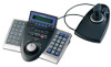
... of matrix switcher for how to check the version. (1) ADDENDUM FOR SYSTEM CONTROLLER WV-CU950/WV-CU650: MATRIX SWITCHER WJ-SX150 SERIES OPERATING PROCEDURES INSTALLATIONS AND CONNECTIONS ■ Basic System Connections • The connection details are applicable for each mode. ■ CONTROLLER NO. The following procedures, all system components. Addendum for WV-CU950/650 and WJ-SX150 Series The descriptions in...
... of matrix switcher for how to check the version. (1) ADDENDUM FOR SYSTEM CONTROLLER WV-CU950/WV-CU650: MATRIX SWITCHER WJ-SX150 SERIES OPERATING PROCEDURES INSTALLATIONS AND CONNECTIONS ■ Basic System Connections • The connection details are applicable for each mode. ■ CONTROLLER NO. The following procedures, all system components. Addendum for WV-CU950/650 and WJ-SX150 Series The descriptions in...
WJSX150 User Guide
Page 36
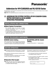
...Series), the following differences will occur. ■ Unavailable Functions through WJ-SX150A Connection The following functions are unavailable when the system controller (WV-CU950 or WV-CU650) is connected to recorders via the matrix switcher (WJ-SX150 Series). ● HD500 V-Multi LCD MENU HDD 204 HD500...514 HD200 Alm Search ■ Functions Only Available with WJ-HD300 Series The following functions are available only when the system controller (WV-CU950 or WV-CU650) is connected to WJHD300 Series via the matrix switcher (WJ-SX150 Series). ■ Functions Only Available with WJ-...
...Series), the following differences will occur. ■ Unavailable Functions through WJ-SX150A Connection The following functions are unavailable when the system controller (WV-CU950 or WV-CU650) is connected to recorders via the matrix switcher (WJ-SX150 Series). ● HD500 V-Multi LCD MENU HDD 204 HD500...514 HD200 Alm Search ■ Functions Only Available with WJ-HD300 Series The following functions are available only when the system controller (WV-CU950 or WV-CU650) is connected to WJHD300 Series via the matrix switcher (WJ-SX150 Series). ■ Functions Only Available with WJ-...
Operating Instructions
Page 1
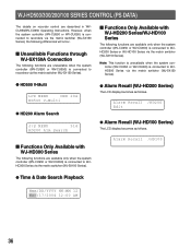
Before attempting to connect or operate this product, please read these instructions carefully and save this manual for future use. Operating Instructions System Controller WV-CU650 Model No.
Before attempting to connect or operate this product, please read these instructions carefully and save this manual for future use. Operating Instructions System Controller WV-CU650 Model No.

Operating Instructions
Page 2
... only shielded interface cables when connecting to the presence of the unit. WARNING: To prevent fire or electric shock hazard, do not expose this equipment. WV-CU650 Serial No. NO USER-SERVICEABLE PARTS INSIDE. Any changes or modifications not expressly approved by the party responsible for a Class A digital device, pursuant to Part...
... only shielded interface cables when connecting to the presence of the unit. WARNING: To prevent fire or electric shock hazard, do not expose this equipment. WV-CU650 Serial No. NO USER-SERVICEABLE PARTS INSIDE. Any changes or modifications not expressly approved by the party responsible for a Class A digital device, pursuant to Part...
Operating Instructions
Page 5
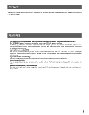
... unit. You can control the camera zooming by moving the zoom wheel controller of cameras and other system units installed in a surveillance system. FEATURES • This product can control two or more PS·Data system devices. In addition, up to 4 system controllers can assign frequently-used functions to the function buttons. PREFACE This product, System Controller WV-CU650, is assignable to...
... unit. You can control the camera zooming by moving the zoom wheel controller of cameras and other system units installed in a surveillance system. FEATURES • This product can control two or more PS·Data system devices. In addition, up to 4 system controllers can assign frequently-used functions to the function buttons. PREFACE This product, System Controller WV-CU650, is assignable to...
Operating Instructions
Page 7
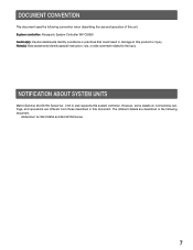
..., settings, and operations are described in the following convention when describing the use and operation of this system controller. Note(s): Note statements identify special instruction, rule, or side comment related to this document. The different...to the topic. NOTIFICATION ABOUT SYSTEM UNITS Matrix Switcher WJ-SX150 Series Ver. 2.03 or later supports this unit. DOCUMENT CONVENTION This document uses the following document. Addendum for WV-CU650 and WJ-SX150 Series 7 System controller: Panasonic System Controller WV-CU650 Caution(s): Caution statements identify conditions...
..., settings, and operations are described in the following convention when describing the use and operation of this system controller. Note(s): Note statements identify special instruction, rule, or side comment related to this document. The different...to the topic. NOTIFICATION ABOUT SYSTEM UNITS Matrix Switcher WJ-SX150 Series Ver. 2.03 or later supports this unit. DOCUMENT CONVENTION This document uses the following document. Addendum for WV-CU650 and WJ-SX150 Series 7 System controller: Panasonic System Controller WV-CU650 Caution(s): Caution statements identify conditions...
Operating Instructions
Page 8
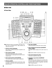
...u Alarm Acknowledge button (ACK) This button is suspended. MAJOR OPERATING CONTROLS AND THEIR FUNCTIONS ■ Main Unit ● Front View #9 $0#8 $1 $2 $3 $4 r qwe t !1 !3 !4 !7 !5 !6 !8 @0 !9 @3 @2 @1 !2 o i u !0 y WV-CU650 ALARM ACK ALM RESET ALM SUSPEND OSD ALM ALL RESET ALM RECALL CAM... FUNC SEQ PAUSE SYS FUNC TOUR SEQ MON LOCK SEQ STOP GROUP SEQ MULTI SCREEN EL-ZOOM LOGOUT GO TO LAST AUX1 ON AUX2 ON MARK ADJUST MENU F1 F2 F3 F4 EXIT ENTER SYSTEM CONTROLLER SHIFT ALM...
...u Alarm Acknowledge button (ACK) This button is suspended. MAJOR OPERATING CONTROLS AND THEIR FUNCTIONS ■ Main Unit ● Front View #9 $0#8 $1 $2 $3 $4 r qwe t !1 !3 !4 !7 !5 !6 !8 @0 !9 @3 @2 @1 !2 o i u !0 y WV-CU650 ALARM ACK ALM RESET ALM SUSPEND OSD ALM ALL RESET ALM RECALL CAM... FUNC SEQ PAUSE SYS FUNC TOUR SEQ MON LOCK SEQ STOP GROUP SEQ MULTI SCREEN EL-ZOOM LOGOUT GO TO LAST AUX1 ON AUX2 ON MARK ADJUST MENU F1 F2 F3 F4 EXIT ENTER SYSTEM CONTROLLER SHIFT ALM...
Operating Instructions
Page 16
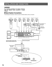
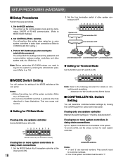
...78 9 10/0 11 12 13 14 15 16 Digital Disk Recorder WJ-HD300 Series To PS·Data ports Used when adding other WV-CU650 system controllers (Available up to p. 18 for details on settings. DC9V IN Fixed Line termination: ON PS·Data Mode OFF ON MODE 901... CONTROLLER No.: 1 Refer to 3) Modular cable (supplied) System Controller WV-CU650 (Main unit) 16 456 456 JOYSTICK SERIAL DATA 901 MODE CONTROLLER NO. 78 78 78 78 23 23 23 23 INSTALLATIONS AND CONNECTIONS WARNING The installations described...
...78 9 10/0 11 12 13 14 15 16 Digital Disk Recorder WJ-HD300 Series To PS·Data ports Used when adding other WV-CU650 system controllers (Available up to p. 18 for details on settings. DC9V IN Fixed Line termination: ON PS·Data Mode OFF ON MODE 901... CONTROLLER No.: 1 Refer to 3) Modular cable (supplied) System Controller WV-CU650 (Main unit) 16 456 456 JOYSTICK SERIAL DATA 901 MODE CONTROLLER NO. 78 78 78 78 23 23 23 23 INSTALLATIONS AND CONNECTIONS WARNING The installations described...
Operating Instructions
Page 18
... when using two or more system controllers in daisy chain connections Up to CONTROLLER NO. Perform WV-CU650 setups after entering the administrator password. Addendum for each system controller. 901 CONTROLLER No. To avoid conflict, set for PS·Data Mode If using two or more system controllers in the system. Set the MODE Switch #5 of the system controller at the chain end to...
... when using two or more system controllers in daisy chain connections Up to CONTROLLER NO. Perform WV-CU650 setups after entering the administrator password. Addendum for each system controller. 901 CONTROLLER No. To avoid conflict, set for PS·Data Mode If using two or more system controllers in the system. Set the MODE Switch #5 of the system controller at the chain end to...
Operating Instructions
Page 25
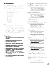
...·Data communication settings. (Refer to p. 20 PS·Data Communication Setting.) • This function is available only among WV-CU650 System Controllers. If the password entered is correct, the LCD display of source system controller becomes as follows. The database copy will be displayed as follows. Data Base Tx Mode Completed Sum=1733 25 switch...
...·Data communication settings. (Refer to p. 20 PS·Data Communication Setting.) • This function is available only among WV-CU650 System Controllers. If the password entered is correct, the LCD display of source system controller becomes as follows. The database copy will be displayed as follows. Data Base Tx Mode Completed Sum=1733 25 switch...


