WJSX150 User Guide
Page 1
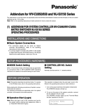
... on . Before starting the following procedures are applicable when the system controller is connected to the matrix switcher. ■ Operation Start (Login) Note: When auto login is set to ON, operators can log into the system without entering their passwords. (Refer to p. 2 Operation Start (Auto Login).) This ... Switch Setting Normally, set to ON. (Refer to the operating instructions of matrix switcher for how to check the version. (1) ADDENDUM FOR SYSTEM CONTROLLER WV-CU950/WV-CU650: MATRIX SWITCHER WJ-SX150 SERIES OPERATING PROCEDURES INSTALLATIONS AND CONNECTIONS ■ Basic...
... on . Before starting the following procedures are applicable when the system controller is connected to the matrix switcher. ■ Operation Start (Login) Note: When auto login is set to ON, operators can log into the system without entering their passwords. (Refer to p. 2 Operation Start (Auto Login).) This ... Switch Setting Normally, set to ON. (Refer to the operating instructions of matrix switcher for how to check the version. (1) ADDENDUM FOR SYSTEM CONTROLLER WV-CU950/WV-CU650: MATRIX SWITCHER WJ-SX150 SERIES OPERATING PROCEDURES INSTALLATIONS AND CONNECTIONS ■ Basic...

WJSX150 User Guide
Page 2
... Cam-- This function is turned on, "Auto Login" appears on the LCD. Terminal Mode No User You can log into the system automatically. "Logout" will blink on the LCD for a specific time, any operators can activate auto logout and set to the operating instructions ...2 seconds, then "Mon -" "Cam - -" automatically appears. To select your operator ID. After the controller is used when an operator leaves the controller or no operation takes place for about 3 seconds. "Password" entry form appears on the LCD for about 3 seconds. 3. Auto login is configurable through WJ-SX150A ...
... Cam-- This function is turned on, "Auto Login" appears on the LCD. Terminal Mode No User You can log into the system automatically. "Logout" will blink on the LCD for a specific time, any operators can activate auto logout and set to the operating instructions ...2 seconds, then "Mon -" "Cam - -" automatically appears. To select your operator ID. After the controller is used when an operator leaves the controller or no operation takes place for about 3 seconds. "Password" entry form appears on the LCD for about 3 seconds. 3. Auto login is configurable through WJ-SX150A ...

WJSX150 User Guide
Page 22
... procedures of WJ-HD300 Series SETUP MENU. The following are using a PS·Data system controller, refer to p. 3 Monitor Selection.) 3. System Setup 301 5On Off WJ-HD300 Series SETUP MENU will appear on this document, may differ ...password, etc. 6. WJ-HD300 SERIES CONTROL (TERMINAL MODE) Matrix switcher can neither connect nor control a WJ-HD300 Series recorder. If you can control the following operating procedures are the same as follows. (Applicable for the terminal mode. Confirm that WJ-HD300 Series is the procedure of WJ-HD300 Series via the system controller...
... procedures of WJ-HD300 Series SETUP MENU. The following are using a PS·Data system controller, refer to p. 3 Monitor Selection.) 3. System Setup 301 5On Off WJ-HD300 Series SETUP MENU will appear on this document, may differ ...password, etc. 6. WJ-HD300 SERIES CONTROL (TERMINAL MODE) Matrix switcher can neither connect nor control a WJ-HD300 Series recorder. If you can control the following operating procedures are the same as follows. (Applicable for the terminal mode. Confirm that WJ-HD300 Series is the procedure of WJ-HD300 Series via the system controller...

Operating Instructions
Page 4
... (Login 29 ■ If You Have Forgotten the Login Password 30 ■ Operation Start (Auto Login 30 ■ Operation End (Logout 30 UNIT SELECTION 31 ■ System Unit Selection 31 ■ Recorder Selection 31 ■ Monitor Selection 32 ■ Camera Selection 32 SYSTEM UNIT CONTROL 33 ■ Multiscreen Display 33 ■ Electronic Zooming 33...
... (Login 29 ■ If You Have Forgotten the Login Password 30 ■ Operation Start (Auto Login 30 ■ Operation End (Logout 30 UNIT SELECTION 31 ■ System Unit Selection 31 ■ Recorder Selection 31 ■ Monitor Selection 32 ■ Camera Selection 32 SYSTEM UNIT CONTROL 33 ■ Multiscreen Display 33 ■ Electronic Zooming 33...
Operating Instructions
Page 5
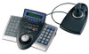
In addition, password is assignable to surveillance control systems. • Improved camera controllability This product has employed a 3D joystick which is separated from the main unit. The system controller has improved functions such as digital disk recorders. • One WV-CU650 System Controller can control cameras, matrix switchers, and recording devices such as camera control, multiscreen segment switching, and search playback...
In addition, password is assignable to surveillance control systems. • Improved camera controllability This product has employed a 3D joystick which is separated from the main unit. The system controller has improved functions such as digital disk recorders. • One WV-CU650 System Controller can control cameras, matrix switchers, and recording devices such as camera control, multiscreen segment switching, and search playback...
Operating Instructions
Page 15
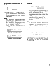
.... • When you have entered a wrong user ID or password, etc. • When you have a camera number or menu number, etc. Check that is not existing. Controller No.1 No Exist Error Controller No.1 No Exist Error This message is displayed when no system controller is set to CONTROLLER NO. 1 (Refer to 256 has been entered. •...
.... • When you have entered a wrong user ID or password, etc. • When you have a camera number or menu number, etc. Check that is not existing. Controller No.1 No Exist Error Controller No.1 No Exist Error This message is displayed when no system controller is set to CONTROLLER NO. 1 (Refer to 256 has been entered. •...
Operating Instructions
Page 18
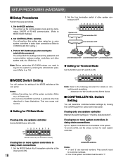
... Line termination switch of RS-485 communication. (Refer to p. 19.) ■ MODE Switch Setting You will determine controller-number settings by moving the CONTROLLER NO. Addendum for each system controller. 901 CONTROLLER No. Perform WV-CU650 setups after entering the administrator password. To avoid conflict, set the unique number for WV-CU650 and WJ-SX150 Series ■...
... Line termination switch of RS-485 communication. (Refer to p. 19.) ■ MODE Switch Setting You will determine controller-number settings by moving the CONTROLLER NO. Addendum for each system controller. 901 CONTROLLER No. Perform WV-CU650 setups after entering the administrator password. To avoid conflict, set the unique number for WV-CU650 and WJ-SX150 Series ■...
Operating Instructions
Page 19
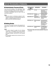
... communication setting can be copied from the following modes. MON (ESC) and 4 PS·Data password display The passwords of up the normal operation mode, turn off the system controller, and then turn on 2, 4, and 6 Setting Mode All reset MON (ESC) and 6 MON... while the power-on the controller again. • The administrator password entry is "650". Notes: • The factory default of your administrator password. ■ Setting Modes If you should change the system from the source system controller (Controller No. 1) to a destination system controller. MON (ESC) and 2...
... communication setting can be copied from the following modes. MON (ESC) and 4 PS·Data password display The passwords of up the normal operation mode, turn off the system controller, and then turn on 2, 4, and 6 Setting Mode All reset MON (ESC) and 6 MON... while the power-on the controller again. • The administrator password entry is "650". Notes: • The factory default of your administrator password. ■ Setting Modes If you should change the system from the source system controller (Controller No. 1) to a destination system controller. MON (ESC) and 2...
Operating Instructions
Page 20
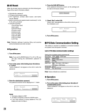
... return to Step 2. Check "End" on the LCD to establish a connection between the system units and system controller. Setup Admin Password _____ 20 Turn on the LCD to enter the password. All Reset 5. If the password entered is correct, all reset. ● Operation 1. Check "End" has appeared on the power while holding down the button 6 and...
... return to Step 2. Check "End" on the LCD to establish a connection between the system units and system controller. Setup Admin Password _____ 20 Turn on the LCD to enter the password. All Reset 5. If the password entered is correct, all reset. ● Operation 1. Check "End" has appeared on the power while holding down the button 6 and...
Operating Instructions
Page 21
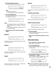
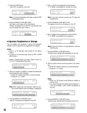
... PS • Data Com. Press the CAM (SET) button. The factory default is sent again (Refer to operate. 7. The password entered will be established between the system controller and other system units. If the password entered is correct, "Baud Rate" setting form will not be displayed as "∗" marks. Setup" will change the setting item...
... PS • Data Com. Press the CAM (SET) button. The factory default is sent again (Refer to operate. 7. The password entered will be established between the system controller and other system units. If the password entered is correct, "Baud Rate" setting form will not be displayed as "∗" marks. Setup" will change the setting item...
Operating Instructions
Page 24
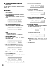
... Password Setup New Password 8. Admin Password Setup New Password 10. Admin Password Setup End Note: If the new password entered is wrong, the LCD display will appear. Enter the current administrator password. If the password entered is correct, "Old Password" entry form will return to perform the setting. The password entered will appear. The new password has been memorized in the system...
... Password Setup New Password 8. Admin Password Setup New Password 10. Admin Password Setup End Note: If the new password entered is wrong, the LCD display will appear. Enter the current administrator password. If the password entered is correct, "Old Password" entry form will return to perform the setting. The password entered will appear. The new password has been memorized in the system...
Operating Instructions
Page 25
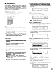
... Base Tx Mode "Enter SET Button" The LCD display of destination system controller(s) become (s) as follows. Connect system controllers with modular cables. 4. The password entered will appear on the power of source and destination system controllers. 2. Set the CONTROLLER NO. If the password entered is identical to destination system controllers (CONTROLLER NO. ■ Database Copy You can copy the following settings. •...
... Base Tx Mode "Enter SET Button" The LCD display of destination system controller(s) become (s) as follows. Connect system controllers with modular cables. 4. The password entered will appear on the power of source and destination system controllers. 2. Set the CONTROLLER NO. If the password entered is identical to destination system controllers (CONTROLLER NO. ■ Database Copy You can copy the following settings. •...
Operating Instructions
Page 26
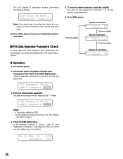
... Rx Mode Completed Sum=1733 Note: If the check sum is not identical, check the connection of source and destination system controllers. ■ PS·Data Operator Password Check In case operators have forgotten their passwords, the administrator can check the passwords in the following procedure. ● Operation 1. Turn off the power of all the...
... Rx Mode Completed Sum=1733 Note: If the check sum is not identical, check the connection of source and destination system controllers. ■ PS·Data Operator Password Check In case operators have forgotten their passwords, the administrator can check the passwords in the following procedure. ● Operation 1. Turn off the power of all the...
Operating Instructions
Page 29
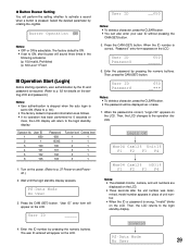
... authentication is skipped when the auto login is set to p. 30.) • The factory default of unit number. • When the ID or password is pressed. Wait until the login standby display appears. Then, the LCD returns to the login standby display. 5. Buzzer Operation ON User ID __650 ...Login OK" appears on the LCD. Press the CAM (SET) button. Press the CAM (SET) button. PS·Data Mode No User 3. User ID Password 650 _____ 6. Invalid 4. Enter the ID number by pressing the numeric buttons. PS • Data Mode No User 29 Then, press the CAM (SET...
... authentication is skipped when the auto login is set to p. 30.) • The factory default of unit number. • When the ID or password is pressed. Wait until the login standby display appears. Then, the LCD returns to the login standby display. 5. Buzzer Operation ON User ID __650 ...Login OK" appears on the LCD. Press the CAM (SET) button. Press the CAM (SET) button. PS·Data Mode No User 3. User ID Password 650 _____ 6. Invalid 4. Enter the ID number by pressing the numeric buttons. PS • Data Mode No User 29 Then, press the CAM (SET...
Operating Instructions
Page 30
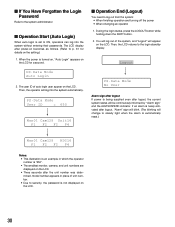
... blinking will appear on the LCD. You will log out of unit number. • Due to security, the password is not displayed on the setting.) 1. Then, the LCD returns to log out from the system: • When finishing operation and turning off the power • When changing an operator 1. PS • ...logout If power is being supplied even after power-on becomes as follows. (Refer to p. 61 for a second. ■ If You Have Forgotten the Login Password Refer to the system administrator. ■ Operation Start (Auto Login) When auto login is set to ON, operators can log into the...
... blinking will appear on the LCD. You will log out of unit number. • Due to security, the password is not displayed on the setting.) 1. Then, the LCD returns to log out from the system: • When finishing operation and turning off the power • When changing an operator 1. PS • ...logout If power is being supplied even after power-on becomes as follows. (Refer to p. 61 for a second. ■ If You Have Forgotten the Login Password Refer to the system administrator. ■ Operation Start (Auto Login) When auto login is set to ON, operators can log into the...
Operating Instructions
Page 59
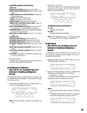
...: Available Only for Switchers Installing Multiplexer Board) If a Multiplexer board is installed inside the switcher, you can activate either of selected system unit will be cleared. Select the camera channel you enter only "0" for all camera channels or spot monitor display, skip this step...CLEAR button (WJ-HD300 Series Only): Clears an entry such as a password. F2: CAM Activates camera picture display. CAM (SET) button: Determines the selected parameter and moves to the sub menu. 4. Available controls and functions Shuttle ring clockwise: Moves to the upper menu. 3D joystick...
...: Available Only for Switchers Installing Multiplexer Board) If a Multiplexer board is installed inside the switcher, you can activate either of selected system unit will be cleared. Select the camera channel you enter only "0" for all camera channels or spot monitor display, skip this step...CLEAR button (WJ-HD300 Series Only): Clears an entry such as a password. F2: CAM Activates camera picture display. CAM (SET) button: Determines the selected parameter and moves to the sub menu. 4. Available controls and functions Shuttle ring clockwise: Moves to the upper menu. 3D joystick...
Operating Instructions
Page 62
...be deactivated. Operator07 404 Function Level = 1 8. Operator07 404 Function Level = 2 Notes: • Refer to p. 29 Operation Start (Login) for the password. Operator07 404 Camera Level = 1 "Erased" will appear on the LCD for the user ID number. "User ID" setting menu will appear on the LCD.... Operator07 404 Password= 333 Note: If you have entered a wrong password, press the CLEAR button. 7. If you try to "99999" are registrable in the system. "Camera Level" setting menu will appear on the LCD. "1" to ...
...be deactivated. Operator07 404 Function Level = 1 8. Operator07 404 Function Level = 2 Notes: • Refer to p. 29 Operation Start (Login) for the password. Operator07 404 Camera Level = 1 "Erased" will appear on the LCD for the user ID number. "User ID" setting menu will appear on the LCD.... Operator07 404 Password= 333 Note: If you have entered a wrong password, press the CLEAR button. 7. If you try to "99999" are registrable in the system. "Camera Level" setting menu will appear on the LCD. "1" to ...

Operating Instructions
Page 74
...entered a wrong user ID. Check the connections. If the password is wrong, the LCD will return to p. 27. play. The display setting value of MODE switches at the rear panel may not be wrong. The setting of system controller was held down . You may be wrong. Check their... with the 3D joystick. Refer to p. 17. If a trouble cannot be disconnected from either the system controller or the AC outlet. Reference Refer to p. 17. Refer to p. 27. Reenter the password correctly. 74 The cable may have entered a wrong pass- Check the settings and turn on the ...
...entered a wrong user ID. Check the connections. If the password is wrong, the LCD will return to p. 27. play. The display setting value of MODE switches at the rear panel may not be wrong. The setting of system controller was held down . You may be wrong. Check their... with the 3D joystick. Refer to p. 17. If a trouble cannot be disconnected from either the system controller or the AC outlet. Reference Refer to p. 17. Refer to p. 27. Reenter the password correctly. 74 The cable may have entered a wrong pass- Check the settings and turn on the ...
