
WJHDE300 User Guide
Page 1
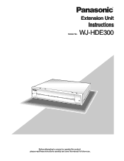
WJ-HDE300 300 Extension Unit WJ-HDE Before attempting to connect or operate this product, please read these instructions carefully and save this manual for future use. Extension Unit Instructions Model No.
WJ-HDE300 300 Extension Unit WJ-HDE Before attempting to connect or operate this product, please read these instructions carefully and save this manual for future use. Extension Unit Instructions Model No.
WJHDE300 User Guide
Page 2
... ON-OFF switch is operated in accordance with or without ON-OFF switches have power supplied to the unit whenever the power cord is inserted into the power source; FCC Caution: To assure continued compliance, (example use only shielded interface cables when connecting to rain or moisture. Any changes or modifications not expressly approved by qualified service personnel or system installers. SA...
... ON-OFF switch is operated in accordance with or without ON-OFF switches have power supplied to the unit whenever the power cord is inserted into the power source; FCC Caution: To assure continued compliance, (example use only shielded interface cables when connecting to rain or moisture. Any changes or modifications not expressly approved by qualified service personnel or system installers. SA...
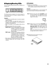
WJHDE300 User Guide
Page 3
... not operate normally, or has been dropped. 3 The wide blade or the third prong are provided for your outlet, consult an electrician for replacement of the obsolete outlet. 10) Protect the power cord from...Install in any ventilation openings. A grounding-type plug has two blades and a third grounding prong. ■ Important Safety Instructions 1) Read these instructions. 2) Keep these instructions. 3) Heed all warnings. 4) Follow all instructions. 5) Do not use this apparatus during lightning storms or when unused for long periods of time. 14) Refer all servicing to qualified service...
... not operate normally, or has been dropped. 3 The wide blade or the third prong are provided for your outlet, consult an electrician for replacement of the obsolete outlet. 10) Protect the power cord from...Install in any ventilation openings. A grounding-type plug has two blades and a third grounding prong. ■ Important Safety Instructions 1) Read these instructions. 2) Keep these instructions. 3) Heed all warnings. 4) Follow all instructions. 5) Do not use this apparatus during lightning storms or when unused for long periods of time. 14) Refer all servicing to qualified service...
WJHDE300 User Guide
Page 5
...hard disk drives per unit to add available disk space to turn on the power of 3 drives to RAID level 5, the digital disk recorder will not access the HDD preinstalled in it, but will be connected...panel, or the HDD POWER switch inside the front lid: before installation. A hard disk drive needs replacing after a certain length (depends on the model) of the disks in the extension unit - 1) The actual space may be operated in the extension unit x (Number of operation. Logical disk size = Smallest size of the disk among the disks in RAID level 5* mode for high tolerance to disk error...
...hard disk drives per unit to add available disk space to turn on the power of 3 drives to RAID level 5, the digital disk recorder will not access the HDD preinstalled in it, but will be connected...panel, or the HDD POWER switch inside the front lid: before installation. A hard disk drive needs replacing after a certain length (depends on the model) of the disks in the extension unit - 1) The actual space may be operated in the extension unit x (Number of operation. Logical disk size = Smallest size of the disk among the disks in RAID level 5* mode for high tolerance to disk error...
WJHDE300 User Guide
Page 6
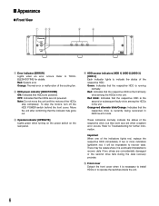
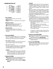
... turning on the power switch on the rear panel. Red blink: Indicates that the respective HDD is necessary to install HDDs or to TROUBLESHOOTING for further information. t Front cover Detach the front cover when it is the first faulty drive among the HDDs in RAID level 5 mode. Refer to operate the switches inside the unit. 6 w HDD power indicator [HDD POWER] ON: Indicates that the HDDs are not powered. r HDD access indicators [HDD 1] [HDD 2] [HDD 3] [HDD...
... turning on the power switch on the rear panel. Red blink: Indicates that the respective HDD is necessary to install HDDs or to TROUBLESHOOTING for further information. t Front cover Detach the front cover when it is the first faulty drive among the HDDs in RAID level 5 mode. Refer to operate the switches inside the unit. 6 w HDD power indicator [HDD POWER] ON: Indicates that the HDDs are not powered. r HDD access indicators [HDD 1] [HDD 2] [HDD 3] [HDD...
WJHDE300 User Guide
Page 7
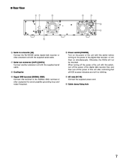
... cable. Otherwise, the HDDs will not be mounted. When turning off the power of this switch before turning on the power of the digital disk recorder, or turn off the power of the unit with the supplied serial cable. ● Rear View yu i EXT IN OUT 21 !2 i o SIGNAL GND POWER AC IN !0 !1 y Serial in connector [IN] Connect the WJ-HD300 series digital disk recorder or other equipment to...
... cable. Otherwise, the HDDs will not be mounted. When turning off the power of this switch before turning on the power of the digital disk recorder, or turn off the power of the unit with the supplied serial cable. ● Rear View yu i EXT IN OUT 21 !2 i o SIGNAL GND POWER AC IN !0 !1 y Serial in connector [IN] Connect the WJ-HD300 series digital disk recorder or other equipment to...
WJHDE300 User Guide
Page 8
... rear panel. !3 Reset button [RESET] This button is selected. Otherwise, the setting of the digital disk recorder may be initialized and it will light. Red: System error Orange: Thermal error or malfunction of the smallest HDD size. To access this happens, ask your dealer to solve the error. • When set to start data recovery. SINGLE: Applies SINGLE mode (no striping across drives for details. Default position Important • Changing the MODE switch...
... rear panel. !3 Reset button [RESET] This button is selected. Otherwise, the setting of the digital disk recorder may be initialized and it will light. Red: System error Orange: Thermal error or malfunction of the smallest HDD size. To access this happens, ask your dealer to solve the error. • When set to start data recovery. SINGLE: Applies SINGLE mode (no striping across drives for details. Default position Important • Changing the MODE switch...
WJHDE300 User Guide
Page 9
... changed after once the system has been operated. ● Procedures 1. Refer to ON (default position). For example, when the HDD 4 of the extension unit 2 will be formatted when a new HDD is added or a preinstalled HDD is replaced, only the HDD4 of the extension unit 2 is removed. Case 1: When the rear of the digital disk recorder and set to RAID5, the digital disk recorder will not access the HDD...
... changed after once the system has been operated. ● Procedures 1. Refer to ON (default position). For example, when the HDD 4 of the extension unit 2 will be formatted when a new HDD is added or a preinstalled HDD is replaced, only the HDD4 of the extension unit 2 is removed. Case 1: When the rear of the digital disk recorder and set to RAID5, the digital disk recorder will not access the HDD...
WJHDE300 User Guide
Page 10
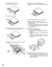
... to the diagram attached on the bracket. 2-2 Slide the front cover to the left. 2-3 Pull the front cover toward you . 3. Do not use an electric screwdriver to change without notice. Prepare the HDDs to fix all the HDDs as master using the jumper connector. Set all the HDDs on the HDD or the operating instructions of the HDD mounting brackets. • Remove the four screws...
... to the diagram attached on the bracket. 2-2 Slide the front cover to the left. 2-3 Pull the front cover toward you . 3. Do not use an electric screwdriver to change without notice. Prepare the HDDs to fix all the HDDs as master using the jumper connector. Set all the HDDs on the HDD or the operating instructions of the HDD mounting brackets. • Remove the four screws...
WJHDE300 User Guide
Page 11
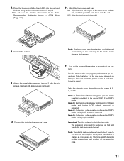
...digital disk recorder is turned on the connections and number of the extension units. 11 tem. Take the steps in SINGLE or RAID5 mode. Case A: Extension units not configured yet and newly installed or added to complete the system check that step 1 in the next page depends on in page 9. Note: The digital disk recorder...plate removed in step 2 with the six screws (marked with the fixed HDDs into the unit and fix them using the four screws removed in step 3. • Do not use an electric screwdriver to the right. 8. Important: Turn the units on how you have cut the motor power in ...
...digital disk recorder is turned on the connections and number of the extension units. 11 tem. Take the steps in SINGLE or RAID5 mode. Case A: Extension units not configured yet and newly installed or added to complete the system check that step 1 in the next page depends on in page 9. Note: The digital disk recorder...plate removed in step 2 with the six screws (marked with the fixed HDDs into the unit and fix them using the four screws removed in step 3. • Do not use an electric screwdriver to the right. 8. Important: Turn the units on how you have cut the motor power in ...
WJHDE300 User Guide
Page 12
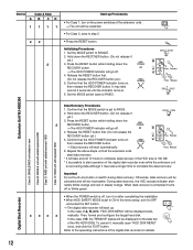
... replaced HDD Data Recovery Procedures 1. HDD POWER OPERATE RECOVER 25 → Data recovery will start up Procedures • For Case 1, turn it on after completing the installation. • When HDD SAFETY MODE is off, turn on the task bar of A, B, or C, "HDD DISK MENU" will go off . 4. Set the MODE switch to RAID5. Release the RESET button first. (Do not release the RECOVER button yet.) 5. Then, format and configure the target hard disk. Digital Disk Recorder...
... replaced HDD Data Recovery Procedures 1. HDD POWER OPERATE RECOVER 25 → Data recovery will start up Procedures • For Case 1, turn it on after completing the installation. • When HDD SAFETY MODE is off, turn on the task bar of A, B, or C, "HDD DISK MENU" will go off . 4. Set the MODE switch to RAID5. Release the RESET button first. (Do not release the RECOVER button yet.) 5. Then, format and configure the target hard disk. Digital Disk Recorder...
WJHDE300 User Guide
Page 14
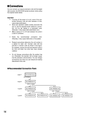
... the digital disk recorder (the WJ-HD300 series) as shown below using the supplied serial cables. You can change connections after the system has run. Otherwise, the recorder will work because of 1 U (44 mm) between the units in a rack for ventilation. • Follow the recommended connection form. Otherwise, it may cause data transmission error. • Make a space of interrupted data transmission. • Never use the...
... the digital disk recorder (the WJ-HD300 series) as shown below using the supplied serial cables. You can change connections after the system has run. Otherwise, the recorder will work because of 1 U (44 mm) between the units in a rack for ventilation. • Follow the recommended connection form. Otherwise, it may cause data transmission error. • Make a space of interrupted data transmission. • Never use the...
WJHDE300 User Guide
Page 15
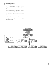
... Connections The figure below shows cable connections. 1. Connect the EXT STORAGE port of the recorder and the IN port of the units. WJ-HD300 Series 4 1 1 SERIAL ALARM 3 2 AUDIO IN AUDIO OUT CASCAKE OUT 2 MONITOR OUT CASCADE IN MONITOR (VGA) ALARM/CONTOROL 16 15 14 13 12 11 10 9 8 7 IN OUT 16 15 14 13 12 11 10 9 8 7 CAMERA MODE COPY PSÆDATA...
... Connections The figure below shows cable connections. 1. Connect the EXT STORAGE port of the recorder and the IN port of the units. WJ-HD300 Series 4 1 1 SERIAL ALARM 3 2 AUDIO IN AUDIO OUT CASCAKE OUT 2 MONITOR OUT CASCADE IN MONITOR (VGA) ALARM/CONTOROL 16 15 14 13 12 11 10 9 8 7 IN OUT 16 15 14 13 12 11 10 9 8 7 CAMERA MODE COPY PSÆDATA...
WJHDE300 User Guide
Page 16
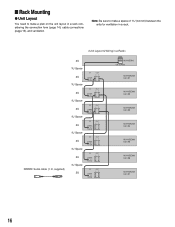
... 2U */ OUT 21 WJ-HDE300 Unit #7 16 Note: Be sure to make a space of 1 U (44 mm) between the units for ventilation in a rack considering the connection form (page 14), cable connections (page 15), and ventilation.
... 2U */ OUT 21 WJ-HDE300 Unit #7 16 Note: Be sure to make a space of 1 U (44 mm) between the units for ventilation in a rack considering the connection form (page 14), cable connections (page 15), and ventilation.
WJHDE300 User Guide
Page 17
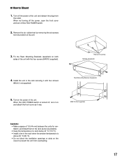
...Turn off the HDD POWER switch. 2. Remove 6 screws M4X10 (Supplied) 4. When not turning off the power, open the front cover and turn it on both sides of the unit with four screws (M5x12, not supplied). Rack Mounting Bracket (Supplied) 5. Fix the Rack Mounting Brackets (supplied) on and attach the front cover as possible. • Keep... the temperature in a rack below 45 °C (113 °F). • Install a fan in the rack securing it was. Turn on the...
...Turn off the HDD POWER switch. 2. Remove 6 screws M4X10 (Supplied) 4. When not turning off the power, open the front cover and turn it on both sides of the unit with four screws (M5x12, not supplied). Rack Mounting Bracket (Supplied) 5. Fix the Rack Mounting Brackets (supplied) on and attach the front cover as possible. • Keep... the temperature in a rack below 45 °C (113 °F). • Install a fan in the rack securing it was. Turn on the...
WJHDE300 User Guide
Page 18
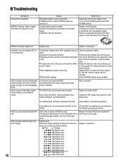
.... MODE switch setting Use the supplied cable. HDD access indicator alternately blinks orange and red or blinks green though no recording/playback. Cooling fan(s) may be used. Install an HDD larger than before although nominally same. Ventilation may be faulty. Turn on the POWER switch and HDD POWER switch. ERROR indicator lights red. System fault Repair is not recognized. Insufficient connector junction Powering up , or rearrange AC mains connection to do Securely connect the power...
.... MODE switch setting Use the supplied cable. HDD access indicator alternately blinks orange and red or blinks green though no recording/playback. Cooling fan(s) may be used. Install an HDD larger than before although nominally same. Ventilation may be faulty. Turn on the POWER switch and HDD POWER switch. ERROR indicator lights red. System fault Repair is not recognized. Insufficient connector junction Powering up , or rearrange AC mains connection to do Securely connect the power...
WJHDE300 User Guide
Page 19
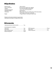
... bracket 2 pcs. ■ Specifications Required power: Power consumption: Interface: Operating temperature: Operating humidity: Dimensions: Weight: 120 V AC 60 Hz 85 W (including 4 HDDs when installed) 2-wire serial, 480 Mbps logical speed +5 °C to +45 °C (41 °F to change without notice. ■ Accessories Operating instructions (this document 1 pc. Power cord 1 pc. Clamp fixing screw 1 pc. 19 HDD fixing screw 16 pcs. Bracket fixing screw 4 pcs. The following...
... bracket 2 pcs. ■ Specifications Required power: Power consumption: Interface: Operating temperature: Operating humidity: Dimensions: Weight: 120 V AC 60 Hz 85 W (including 4 HDDs when installed) 2-wire serial, 480 Mbps logical speed +5 °C to +45 °C (41 °F to change without notice. ■ Accessories Operating instructions (this document 1 pc. Power cord 1 pc. Clamp fixing screw 1 pc. 19 HDD fixing screw 16 pcs. Bracket fixing screw 4 pcs. The following...


