
Functional Instructions
Page 2
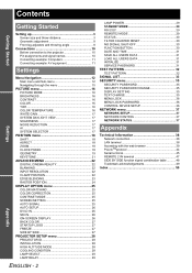
... - 2 LAMP POWER 29 STANDBY MODE 29 RS-232C 29 REMOTE2 MODE 29 STATUS 30 FILTER COUNTER RESET 30 NO SIGNAL SHUT-OFF 30 FUNCTION BUTTON 30 DATE AND TIME 31 SAVE ALL USERS DATA 31 LOAD ALL USERS DATA 31 INITIALIZE 31 SERVICE PASSWORD 31 TEST PATTERN 32 TEST PATTERN 32 SIGNAL LIST 33 SECURITY menu 35 SECURITY PASSWORD 35 SECURITY PASSWORD CHANGE 35 DISPLAY SETTING 35 TEXT CHANGE 35 MENU LOCK 36 MENU LOCK PASSWORD 36 CONTROL DEVICE SETUP 36 NETWORK menu 37 NETWORK SETUP 37 NETWORK CONTROL 37 NETWORK STATUS...
... - 2 LAMP POWER 29 STANDBY MODE 29 RS-232C 29 REMOTE2 MODE 29 STATUS 30 FILTER COUNTER RESET 30 NO SIGNAL SHUT-OFF 30 FUNCTION BUTTON 30 DATE AND TIME 31 SAVE ALL USERS DATA 31 LOAD ALL USERS DATA 31 INITIALIZE 31 SERVICE PASSWORD 31 TEST PATTERN 32 TEST PATTERN 32 SIGNAL LIST 33 SECURITY menu 35 SECURITY PASSWORD 35 SECURITY PASSWORD CHANGE 35 DISPLAY SETTING 35 TEXT CHANGE 35 MENU LOCK 36 MENU LOCK PASSWORD 36 CONTROL DEVICE SETUP 36 NETWORK menu 37 NETWORK SETUP 37 NETWORK CONTROL 37 NETWORK STATUS...
Functional Instructions
Page 17
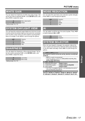
... Low Middle High SYSTEM DAYLIGHT VIEW You can select manually. I H to cycle through the options. I H to +10 More natural white Whiter NOISE REDUCTION You can switch on/off the auto iris control system. PICTURE menu WHITE GAIN You can adjust the brightness of white area of compatible signals" in welllit rooms where the ambient light sources cannot be controlled, such as when a door opens or when window coverings fail...
... Low Middle High SYSTEM DAYLIGHT VIEW You can select manually. I H to cycle through the options. I H to +10 More natural white Whiter NOISE REDUCTION You can switch on/off the auto iris control system. PICTURE menu WHITE GAIN You can adjust the brightness of white area of compatible signals" in welllit rooms where the ambient light sources cannot be controlled, such as when a door opens or when window coverings fail...

Functional Instructions
Page 22
... POSITION When black part of the image to change , and I H to 2:2 pulldown. H: Moves the inner edge of the image to the selected input signal. ADVANCED MENU Remote control See "Navigating through the options. Detects only NTSC 480i and 1080/60i signals, and adjust the vertical resolution of the blank area to the best colour. UPPER LOWER Q Setting range Models PT-DZ6710E/PT-DZ6700E PT-DW6300E PT-D6000E Vertical...
... POSITION When black part of the image to change , and I H to 2:2 pulldown. H: Moves the inner edge of the image to the selected input signal. ADVANCED MENU Remote control See "Navigating through the options. Detects only NTSC 480i and 1080/60i signals, and adjust the vertical resolution of the blank area to the best colour. UPPER LOWER Q Setting range Models PT-DZ6710E/PT-DZ6700E PT-DW6300E PT-D6000E Vertical...
Functional Instructions
Page 26
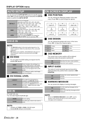
... For specific resolution signals Select the required MODE and change the DISPLAY DOTS value by pressing I H to black ON-SCREEN DISPLAY J OSD POSITION You can prevent the display of the main menu. EDID3 EDID1 EDID2(PC) Switch between fine settings for a moving image, such as signals from a DVD player. ON OFF Memorise the menu cursor position. Deactive J WARNING MESSAGE You can change the AUTO SETUP feature for specific signals. HDMI conversion cable connection SDI IN (PT-DZ6710E...
... For specific resolution signals Select the required MODE and change the DISPLAY DOTS value by pressing I H to black ON-SCREEN DISPLAY J OSD POSITION You can prevent the display of the main menu. EDID3 EDID1 EDID2(PC) Switch between fine settings for a moving image, such as signals from a DVD player. ON OFF Memorise the menu cursor position. Deactive J WARNING MESSAGE You can change the AUTO SETUP feature for specific signals. HDMI conversion cable connection SDI IN (PT-DZ6710E...
Functional Instructions
Page 29
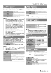
... cumulative operating time (when HIGH is repeatedly used as the LAMP POWER setting), the other lamp will light. After both lamps remain off first. GROUP Select A to be changed depending on in standby mode is not necessary. PIN1 PIN2 PIN3 - LAMP POWER The luminance of the projection lamp can be replaced more , this setting can be turned off or the 2 000 hours of use lamp will light. Set when high brightness is 10 W. USER For changing an optional input...
... cumulative operating time (when HIGH is repeatedly used as the LAMP POWER setting), the other lamp will light. After both lamps remain off first. GROUP Select A to be changed depending on in standby mode is not necessary. PIN1 PIN2 PIN3 - LAMP POWER The luminance of the projection lamp can be replaced more , this setting can be turned off or the 2 000 hours of use lamp will light. Set when high brightness is 10 W. USER For changing an optional input...
Functional Instructions
Page 30
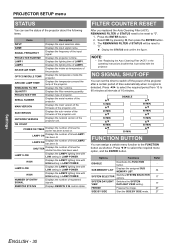
... lighting time with LOW setting in LAMP POWER. Displays the intake air temperature of the projector. SUB VERSION Displays the sub version of the firmware of the input signal. Press the ENTER button. 2. FG FUNCTION BUTTON You can assign a certain menu function to "0". SUB MEMORY LIST Displays the assigned SUB MEMORY LIST. LAMP2 LOW Displays the LAMP2 lighting time with LOW setting in LAMP POWER. Display the STATUS and confirm the figure. FILTER COUNTER RESET After you replaced the Auto Cleaning Filter...
... lighting time with LOW setting in LAMP POWER. Displays the intake air temperature of the projector. SUB VERSION Displays the sub version of the firmware of the input signal. Press the ENTER button. 2. FG FUNCTION BUTTON You can assign a certain menu function to "0". SUB MEMORY LIST Displays the assigned SUB MEMORY LIST. LAMP2 LOW Displays the LAMP2 lighting time with LOW setting in LAMP POWER. Display the STATUS and confirm the figure. FILTER COUNTER RESET After you replaced the Auto Cleaning Filter...

Functional Instructions
Page 34
... the screen after adjustment. Sub memory data contains the setting information of corresponding sub memory data to the signal. Press I or H while the menu is cleared from the same input source. Displays the REGISTERED SIGNAL STATUS. 3. SIGNAL LIST J Managing the sub memory list You can return to the previous step by pressing the MENU button. 3. Displays the list of screen and image adjustments, such as follows. Displays sub memory status and...
... the screen after adjustment. Sub memory data contains the setting information of corresponding sub memory data to the signal. Press I or H while the menu is cleared from the same input source. Displays the REGISTERED SIGNAL STATUS. 3. SIGNAL LIST J Managing the sub memory list You can return to the previous step by pressing the MENU button. 3. Displays the list of screen and image adjustments, such as follows. Displays sub memory status and...
Functional Instructions
Page 44
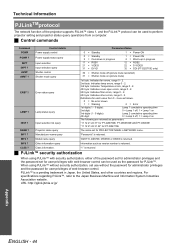
... Indicates fan errors, range 0 - 2. 2nd byte: Indicates lamp errors, range 0 - 2. 3rd byte: Indicates Temperature errors, range 0 - 2. 4th byte: Indicates cover open errors, range 0 - 2. 5th byte: Indicates filter errors, range 0 - 2. 6th byte: Indicates other countries and regions. Control details Power supply control Power supply status query Input selection Input selection query Shutter control Shutter mode query ERST ? NAME ? INF0 ? "1" is returned J PJLink™ security authorization When using PJLink™ without security authorization, set use without the password...
... Indicates fan errors, range 0 - 2. 2nd byte: Indicates lamp errors, range 0 - 2. 3rd byte: Indicates Temperature errors, range 0 - 2. 4th byte: Indicates cover open errors, range 0 - 2. 5th byte: Indicates filter errors, range 0 - 2. 6th byte: Indicates other countries and regions. Control details Power supply control Power supply status query Input selection Input selection query Shutter control Shutter mode query ERST ? NAME ? INF0 ? "1" is returned J PJLink™ security authorization When using PJLink™ without security authorization, set use without the password...
Functional Instructions
Page 50
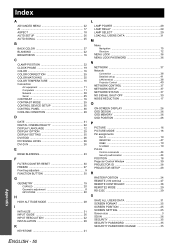
... 23 F FILTER COUNTER RESET 30 FREEZE 27 Front leg adjusters 9 FUNCTION BUTTON 30 G GEOMETRY 19 CURVED 20 Geometric adjustment 8 KEYSTONE 20 H HIGH ALTITUDE MODE 28 I INITIALIZE 31 INPUT GUIDE 26 INPUT RESOLUTION 22 INSTALLATION 28 K KEYSTONE 21 L LAMP POWER 29 LAMP RELAY 29 LAMP SELECT 29 LOAD ALL USERS DATA 31 M Menu Navigation 15 Structure 12 MENU LOCK 36 MENU LOCK PASSWORD 36 N NETWORK 37 Network Connection 38 Detailed set up 41 LAN terminal 38 Projector Control 40 NETWORK CONTROL 37 NETWORK SETUP 37 NETWORK STATUS 37 NO SIGNAL SHUT-OFF 30...
... 23 F FILTER COUNTER RESET 30 FREEZE 27 Front leg adjusters 9 FUNCTION BUTTON 30 G GEOMETRY 19 CURVED 20 Geometric adjustment 8 KEYSTONE 20 H HIGH ALTITUDE MODE 28 I INITIALIZE 31 INPUT GUIDE 26 INPUT RESOLUTION 22 INSTALLATION 28 K KEYSTONE 21 L LAMP POWER 29 LAMP RELAY 29 LAMP SELECT 29 LOAD ALL USERS DATA 31 M Menu Navigation 15 Structure 12 MENU LOCK 36 MENU LOCK PASSWORD 36 N NETWORK 37 Network Connection 38 Detailed set up 41 LAN terminal 38 Projector Control 40 NETWORK CONTROL 37 NETWORK SETUP 37 NETWORK STATUS 37 NO SIGNAL SHUT-OFF 30...
Operating Instructions
Page 5
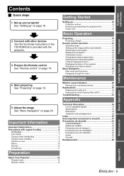
... your projector See "Setting up" on page 24. Adjust the image See "Menu Navigation" on page 16. Prepare the Remote control See "Remote control" on page 19. Projecting 19 Projecting a image 19 Remote control operation 21 Operating range 21 Setting up 16 Projection method 16 Removing and attaching the projection lens 17 Power cord 18 Basic Operation 2. Setting up the image position automatically 21 Switching the input signal 22 Stopping the projection 22 Clearing the screen 22 Changing the picture aspect ratio 22 Displaying...
... your projector See "Setting up" on page 24. Adjust the image See "Menu Navigation" on page 16. Prepare the Remote control See "Remote control" on page 19. Projecting 19 Projecting a image 19 Remote control operation 21 Operating range 21 Setting up 16 Projection method 16 Removing and attaching the projection lens 17 Power cord 18 Basic Operation 2. Setting up the image position automatically 21 Switching the input signal 22 Stopping the projection 22 Clearing the screen 22 Changing the picture aspect ratio 22 Displaying...
Operating Instructions
Page 9
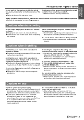
... the lamp may be handled with care. Important Information Precautions with regard to safety Do not reach for the openings beside the optical lens, during transport. Avoid setting up the projector near high-voltage power lines or near an air conditioner or lighting equipment. ET-PKF100H, ET-PKF100S). If using the projector, close the front panel cover. Be sure to preserve and maintain a clean...
... the lamp may be handled with care. Important Information Precautions with regard to safety Do not reach for the openings beside the optical lens, during transport. Avoid setting up the projector near high-voltage power lines or near an air conditioner or lighting equipment. ET-PKF100H, ET-PKF100S). If using the projector, close the front panel cover. Be sure to preserve and maintain a clean...

Operating Instructions
Page 13
... DVI-D signals. computer. Auto Cleaning Filter (ACF) compartment (page 31) NOTE: • Switch on /off. (page 20) AC IN terminal Connect the power cord to supply electronic power to the projector. (page 20) Security lock Attach the commercial shackle lock, manufactured by Kensington, to a computer. ENGLISH - 13 Air intake port Air intake port POWER button Switch the projector on the POWER button of the projector body that is located near the terminals before using the control buttons. •...
... DVI-D signals. computer. Auto Cleaning Filter (ACF) compartment (page 31) NOTE: • Switch on /off. (page 20) AC IN terminal Connect the power cord to supply electronic power to the projector. (page 20) Security lock Attach the commercial shackle lock, manufactured by Kensington, to a computer. ENGLISH - 13 Air intake port Air intake port POWER button Switch the projector on the POWER button of the projector body that is located near the terminals before using the control buttons. •...
Operating Instructions
Page 16
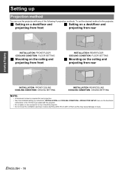
Getting Started Setting up instructions, INSTALLATION and COOLING CONDITION in PROJECTOR SETUP menu on the functional instructions in the projector, J Setting on a desk/floor and J Setting on a desk/floor and projecting from front projecting from rear INSTALLATION: FRONT/FLOOR COOLING CONDITION: FLOOR SETTING J Mounting on the ceiling and projecting from front INSTALLATION: REAR/FLOOR COOLING CONDITION: FLOOR SETTING J Mounting on top of another projector. • Do not cover the ventilation openings or place anything within...
Getting Started Setting up instructions, INSTALLATION and COOLING CONDITION in PROJECTOR SETUP menu on the functional instructions in the projector, J Setting on a desk/floor and J Setting on a desk/floor and projecting from front projecting from rear INSTALLATION: FRONT/FLOOR COOLING CONDITION: FLOOR SETTING J Mounting on the ceiling and projecting from front INSTALLATION: REAR/FLOOR COOLING CONDITION: FLOOR SETTING J Mounting on top of another projector. • Do not cover the ventilation openings or place anything within...
Operating Instructions
Page 19
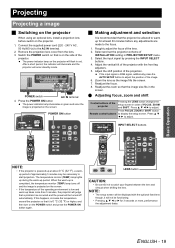
... the image. 6. The power indicator lamp on the projector will flash in PROJECTOR SETUP menu. 3. Adjust the vertical tilt of the projector with the optional fixed lens though, it is 0 °C (32 °F) or higher, and then turn on the side of INSTALLATION setting in red. If the input signal is projected on the screen. Readjust the focus. 8. INPUT SELECT buttons Basic Operation . Remove the projection lens cover from the lens. 3. Select and set the projection scheme of the projector. Press FOCUS, ZOOM or SHIFT button Remote control buttons...
... the image. 6. The power indicator lamp on the projector will flash in PROJECTOR SETUP menu. 3. Adjust the vertical tilt of the projector with the optional fixed lens though, it is 0 °C (32 °F) or higher, and then turn on the side of INSTALLATION setting in red. If the input signal is projected on the screen. Readjust the focus. 8. INPUT SELECT buttons Basic Operation . Remove the projection lens cover from the lens. 3. Select and set the projection scheme of the projector. Press FOCUS, ZOOM or SHIFT button Remote control buttons...
Operating Instructions
Page 20
... operating, do not place the projector inside a box or bag. The projection of the image stops, and the power indicator of the projector turns to OFF. Using the standard projection position as this may cause a change in the figures below. The confirmation screen will be displayed. When the power indicator of the projector lights up even if the power is still running . 3. Press the POWER STANDBY button. Projecting J Switching off , the lamp will not light...
... operating, do not place the projector inside a box or bag. The projection of the image stops, and the power indicator of the projector turns to OFF. Using the standard projection position as this may cause a change in the figures below. The confirmation screen will be displayed. When the power indicator of the projector lights up even if the power is still running . 3. Press the POWER STANDBY button. Projecting J Switching off , the lamp will not light...
Operating Instructions
Page 28
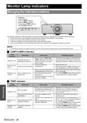
... the screen unit used hours have reached 1 800 hours. replacing the lamp unit when turning on the projector in proper way and contact the dealer. • Turn off ? Error is installed and still having an lower than approx. 0 °C (32 °F)? indication displayed? • Turn off the POWER switch of the projector in the current status. Monitor Lamp indicators Managing the indicated problems Indicators Power indicator Lamp1 (LAMP1) indicator Lamp2 (LAMP2) indicator Temperature (TEMP) indicator Filter (FILTER) indicator STANDBY(RED)/ ON(GREEN) LAMP TEMP FILTER...
... the screen unit used hours have reached 1 800 hours. replacing the lamp unit when turning on the projector in proper way and contact the dealer. • Turn off ? Error is installed and still having an lower than approx. 0 °C (32 °F)? indication displayed? • Turn off the POWER switch of the projector in the current status. Monitor Lamp indicators Managing the indicated problems Indicators Power indicator Lamp1 (LAMP1) indicator Lamp2 (LAMP2) indicator Temperature (TEMP) indicator Filter (FILTER) indicator STANDBY(RED)/ ON(GREEN) LAMP TEMP FILTER...

Operating Instructions
Page 29
Blinking in red Lighting in orange Blinking in red. *2. 200 hours is the roughly guided time. When the ACF unit is operating, operational sound may cause malfunction of STATUS in red • Check the REMAINING FILTER • Replace the ACF unit. Contact the dealer to purchase the new of STATUS in PROJECTOR SETUP menu is not installed.*1 The ACF unit remains few. message and power off with the indicator blinking in orange The ACF unit is OFF, it may...
Blinking in red Lighting in orange Blinking in red. *2. 200 hours is the roughly guided time. When the ACF unit is operating, operational sound may cause malfunction of STATUS in red • Check the REMAINING FILTER • Replace the ACF unit. Contact the dealer to purchase the new of STATUS in PROJECTOR SETUP menu is not installed.*1 The ACF unit remains few. message and power off with the indicator blinking in orange The ACF unit is OFF, it may...
Operating Instructions
Page 30
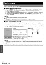
... you keep using LAMP1/ LAMP2 of the replacement timing at 1 800 hours, and at 2 000 hours, the projector will inform you respond. On screen LAMP indicator Indication REPLACE LAMP Over 1 800 hours Over 2 000 hours "REPLACE LAMP" is mounted on the upper left Lights in red of the screen, and it will be turned off. Press any button. Wait for 10 minutes. When the projector is displayed on the ceiling, do not work directly under the projector or...
... you keep using LAMP1/ LAMP2 of the replacement timing at 1 800 hours, and at 2 000 hours, the projector will inform you respond. On screen LAMP indicator Indication REPLACE LAMP Over 1 800 hours Over 2 000 hours "REPLACE LAMP" is mounted on the upper left Lights in red of the screen, and it will be turned off. Press any button. Wait for 10 minutes. When the projector is displayed on the ceiling, do not work directly under the projector or...
Operating Instructions
Page 31
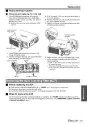
... cover to the projector's connector. The FILTER indicator will inform you of the lamp unit cover is consumable product and effects on the back of STATUS in REMAINING FILTER of the projector until the screws turn off the POWER switch of the projector in correct direction. 5. Make sure the fan electric power connector of the replacement timing. Press in to remove the 3 lamp unit fixing screws. 3. Lamp unit cover fixing screw Replacement 4. Handle Lamp unit screws Replacing the Auto Cleaning Filter (ACF) J Before replacing...
... cover to the projector's connector. The FILTER indicator will inform you of the lamp unit cover is consumable product and effects on the back of STATUS in REMAINING FILTER of the projector until the screws turn off the POWER switch of the projector in correct direction. 5. Make sure the fan electric power connector of the replacement timing. Press in to remove the 3 lamp unit fixing screws. 3. Lamp unit cover fixing screw Replacement 4. Handle Lamp unit screws Replacing the Auto Cleaning Filter (ACF) J Before replacing...
Operating Instructions
Page 33
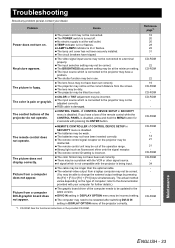
... connected to the projector may be dirty. REMOTE CONTROLLER of the projector do not operate. DVI-D IN setting in use. The control buttons of CONTROL DEVICE SETUP in the provided CD-ROM. The color format may be adjusted correctly. The color is incorrect. The video signal input source may be able to a terminal properly. The projector may be weak. Picture from a laptop computer may not be correct. (You may not be connected to change...
... connected to the projector may be dirty. REMOTE CONTROLLER of the projector do not operate. DVI-D IN setting in use. The control buttons of CONTROL DEVICE SETUP in the provided CD-ROM. The color format may be adjusted correctly. The color is incorrect. The video signal input source may be able to a terminal properly. The projector may be weak. Picture from a laptop computer may not be correct. (You may not be connected to change...


