Installation Guide
Page 1
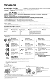
...C Built-in alarm) C E POWER indicator*2 D F AV LINK indicator*3 G Microphone I H Lens cover E I /O interface S P FACTORY DEFAULT RESET button Q Safety wire hole R WIRELESS/WIRED switch S Cable cover XWG26D12VW Used when securing the safety wire to the wall. XWG4F16VW Used when securing the safety wire to be accessed using the camera. Important Information (1 pc.) Installation Guide (this document) (1 pc.) Setup Guide (1 pc.) Setup Guide (for VIERA Connection) (1pc.) [BL-C230A Only] J Wall mounting holes K Tripod mounting hole L Serial number and MAC address label M LAN port N DC...
...C Built-in alarm) C E POWER indicator*2 D F AV LINK indicator*3 G Microphone I H Lens cover E I /O interface S P FACTORY DEFAULT RESET button Q Safety wire hole R WIRELESS/WIRED switch S Cable cover XWG26D12VW Used when securing the safety wire to the wall. XWG4F16VW Used when securing the safety wire to be accessed using the camera. Important Information (1 pc.) Installation Guide (this document) (1 pc.) Setup Guide (1 pc.) Setup Guide (for VIERA Connection) (1pc.) [BL-C230A Only] J Wall mounting holes K Tripod mounting hole L Serial number and MAC address label M LAN port N DC...
Installation Guide
Page 2
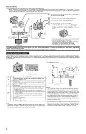
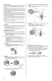
... that the WIRELESS/WIRED switch on the bottom of a network error or failure. The camera can be triggered by following the procedure described in the included Setup Guide. • If the indicator does not turn green, see 1.2 POWER Indicator Issues in the Troubleshooting Guide on the included CD-ROM. GND terminal. The camera can be changed (see 7.4 Controlling the External Output Terminal (BL-C230 Only) in the Operating Instructions on the...
... that the WIRELESS/WIRED switch on the bottom of a network error or failure. The camera can be triggered by following the procedure described in the included Setup Guide. • If the indicator does not turn green, see 1.2 POWER Indicator Issues in the Troubleshooting Guide on the included CD-ROM. GND terminal. The camera can be changed (see 7.4 Controlling the External Output Terminal (BL-C230 Only) in the Operating Instructions on the...
Installation Guide
Page 3
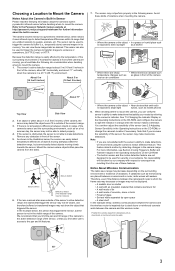
... FTP, E-mail, or HTTP. Position the camera away from the sides. If there is no temperature difference between the camera and router is aimed at http://panasonic.net/pcc/support/netwkcam/ for security or surveillance. We recommend that emit radio is exposed to bright light waves, such as steel doors or reinforced concrete walls. 58° 3 See 7.5 Changing the Indicator Display in the Operating Instructions...
... FTP, E-mail, or HTTP. Position the camera away from the sides. If there is no temperature difference between the camera and router is aimed at http://panasonic.net/pcc/support/netwkcam/ for security or surveillance. We recommend that emit radio is exposed to bright light waves, such as steel doors or reinforced concrete walls. 58° 3 See 7.5 Changing the Indicator Display in the Operating Instructions...
Installation Guide
Page 4
... camera, to the camera and attach the cable cover. • Insert the LAN cable until it would not fall and be accessed, simply press the PRIVACY button again. You can also turn green within a few seconds. The camera's administrator can turn privacy mode off , users can be accessed by hiding the lens inside the camera, preventing camera images from being seen. Secure the safety wire to the wall using supplemental lighting...
... camera, to the camera and attach the cable cover. • Insert the LAN cable until it would not fall and be accessed, simply press the PRIVACY button again. You can also turn green within a few seconds. The camera's administrator can turn privacy mode off , users can be accessed by hiding the lens inside the camera, preventing camera images from being seen. Secure the safety wire to the wall using supplemental lighting...


