Installation Guide
Page 1
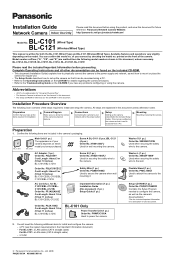
Panasonic Network Camera Website: http://panasonic.net/pcc/products/netwkcam/ BL-C101 Model No. (Wired Type) BL-C121 (Wireless/Wired Type) This manual is an overview of each document. 2. All steps are explained in the included Setup Guide). Preparation Confirm that you have all other documentation can be accessed from the following additional items to power the camera. Setup Setting...
Panasonic Network Camera Website: http://panasonic.net/pcc/products/netwkcam/ BL-C101 Model No. (Wired Type) BL-C121 (Wireless/Wired Type) This manual is an overview of each document. 2. All steps are explained in the included Setup Guide). Preparation Confirm that you have all other documentation can be accessed from the following additional items to power the camera. Setup Setting...
Installation Guide
Page 2
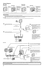
...8226; The camera may become warm. BL-C121 Internet PC 1 Confirm that your router or to the Panasonic Network Camera website (http://panasonic.net/pcc/... confirm that the WIRELESS/WIRED switch on the side of the camera is enabled. (...Panasonic AC adaptor AC adaptor (Order No. PQLV206Y for BL-C121A, PQLV216CE1Z for BLC101CE, BL-C101E). • The camera may become warm. To the power • Confirm that is connected to the router and the power transfer unit. Camera Diagrams BL-C101 Front View Rear View A Indicator*1 B Lens D A C Microphone B C BL-C121...
...8226; The camera may become warm. BL-C121 Internet PC 1 Confirm that your router or to the Panasonic Network Camera website (http://panasonic.net/pcc/... confirm that the WIRELESS/WIRED switch on the side of the camera is enabled. (...Panasonic AC adaptor AC adaptor (Order No. PQLV206Y for BL-C121A, PQLV216CE1Z for BLC101CE, BL-C101E). • The camera may become warm. To the power • Confirm that is connected to the router and the power transfer unit. Camera Diagrams BL-C101 Front View Rear View A Indicator*1 B Lens D A C Microphone B C BL-C121...
Installation Guide
Page 3
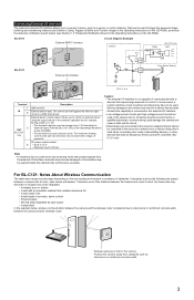
... from the external I/O interface, terminals may become unusable. BL-C101 External INPUT interface Circuit Diagram Example Camera Relay BL-C121 only Light 9 V* BL-C121 External I /O interface is impaired due to steel doors or reinforced concrete walls between the camera and the wireless router is not capable of a network error or failure. External device control output. In some cases, a custom...
... from the external I/O interface, terminals may become unusable. BL-C101 External INPUT interface Circuit Diagram Example Camera Relay BL-C121 only Light 9 V* BL-C121 External I /O interface is impaired due to steel doors or reinforced concrete walls between the camera and the wireless router is not capable of a network error or failure. External device control output. In some cases, a custom...


