
Owner Manual
Page 1
Following the instructions in this manual thoroughly before making connections and plugging in the unit. AV Receiver TX-SR707 Instruction Manual Thank you to obtain optimum performance and listening enjoyment from your new AV Receiver. Contents Introduction 2 Connection 17 Turning On & First Time Setup .....40 Basic Operations 56 Using the Listening Modes ........69 Advanced Setup 79 Zone 2 102 Controlling Other Components ...108 Others 121 En Please read this manual will enable you for future reference. Please retain this manual for purchasing an Onkyo AV Receiver.
Following the instructions in this manual thoroughly before making connections and plugging in the unit. AV Receiver TX-SR707 Instruction Manual Thank you to obtain optimum performance and listening enjoyment from your new AV Receiver. Contents Introduction 2 Connection 17 Turning On & First Time Setup .....40 Basic Operations 56 Using the Listening Modes ........69 Advanced Setup 79 Zone 2 102 Controlling Other Components ...108 Others 121 En Please read this manual will enable you for future reference. Please retain this manual for purchasing an Onkyo AV Receiver.

Owner Manual
Page 4
...cut it off and fit a suitable plug. Fit a suitable fuse in your AC outlet does not match with the plug on the AV receiver's power cord (adapter varies from country to country.) Speaker cable labels * Power-plug adapter Only supplied in compliance with the corresponding technical... standards such as that the ONKYO product described in this instruction manual is coloured brown must approved by qualified service personnel. The wire which is in certain countries....
...cut it off and fit a suitable plug. Fit a suitable fuse in your AC outlet does not match with the plug on the AV receiver's power cord (adapter varies from country to country.) Speaker cable labels * Power-plug adapter Only supplied in compliance with the corresponding technical... standards such as that the ONKYO product described in this instruction manual is coloured brown must approved by qualified service personnel. The wire which is in certain countries....

Owner Manual
Page 5
... 37 Connecting an RI Dock 38 Connecting a Dock with the Universal Port Connector 38 Connecting Onkyo V Components 39 Connecting the Power Cord 39 Turning On & First Time Setup Turning On the AV receiver 40 Turning On and Standby 40 First Time Setup 41 Selecting the Language used for the ... 56 Selecting the Input Source 56 Adjusting the Bass & Treble 57 Displaying Source Information 57 Setting the Display Brightness 57 Muting the AV Receiver 58 Using the Sleep Timer 58 Selecting Speaker Layout 58 Using Headphones 58 Using Easy Macros 59 Listening to the Radio 61 Using ...
... 37 Connecting an RI Dock 38 Connecting a Dock with the Universal Port Connector 38 Connecting Onkyo V Components 39 Connecting the Power Cord 39 Turning On & First Time Setup Turning On the AV receiver 40 Turning On and Standby 40 First Time Setup 41 Selecting the Language used for the ... 56 Selecting the Input Source 56 Adjusting the Bass & Treble 57 Displaying Source Information 57 Setting the Display Brightness 57 Muting the AV Receiver 58 Using the Sleep Timer 58 Selecting Speaker Layout 58 Using Headphones 58 Using Easy Macros 59 Listening to the Radio 61 Using ...

Owner Manual
Page 8
... button is used for clarity. See "Using RDS (European models)" on page 10. D ZONE 2 indicator (105) This indicator lights up when the AV receiver is in areas where RDS broadcasts are not shown here for RDS (Radio Data System). H Display See "Display" on page 63. L GAME button ...MOVIE/TV button (69) Selects the listening modes intended for use with music. N MEMORY button (62) This button is used to set the AV receiver to On or Standby. Q SETUP button This button is used to display various information about the currently selected input source. Front & Rear Panels ...
... button is used for clarity. See "Using RDS (European models)" on page 10. D ZONE 2 indicator (105) This indicator lights up when the AV receiver is in areas where RDS broadcasts are not shown here for RDS (Radio Data System). H Display See "Display" on page 63. L GAME button ...MOVIE/TV button (69) Selects the listening modes intended for use with music. N MEMORY button (62) This button is used to set the AV receiver to On or Standby. Q SETUP button This button is used to display various information about the currently selected input source. Front & Rear Panels ...

Owner Manual
Page 9
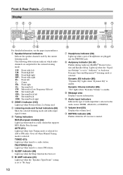
.../DVR, CBL/SAT, GAME, AUX, TV/TAPE, TUNER, CD, PHONO, PORT. U PHONES jack (58) This 1/4-inch phone jack is for connecting a standard pair of the AV receiver to -2 dB, -81.5 dB through +18.0 dB (relative display). W PURE AUDIO button and indicator (69) Selects the Pure Audio listening mode. X Input selector buttons (56...
.../DVR, CBL/SAT, GAME, AUX, TV/TAPE, TUNER, CD, PHONO, PORT. U PHONES jack (58) This 1/4-inch phone jack is for connecting a standard pair of the AV receiver to -2 dB, -81.5 dB through +18.0 dB (relative display). W PURE AUDIO button and indicator (69) Selects the Pure Audio listening mode. X Input selector buttons (56...
Owner Manual
Page 10
...): "Dynamic EQ" lights when "Dynamic EQ" is enable. Dynamic Volume indicator (86): "Vol" lights when "Dynamic Volume" is enable. M MUTING indicator (58) Flashes while the AV receiver is selected. J Message area Displays various information. B Speaker/channel indicators Indicate the speaker channels used . Goes off when Manual Tuning mode is muted. G Bi AMP...
...): "Dynamic EQ" lights when "Dynamic EQ" is enable. Dynamic Volume indicator (86): "Vol" lights when "Dynamic Volume" is enable. M MUTING indicator (58) Flashes while the AV receiver is selected. J Message area Displays various information. B Speaker/channel indicators Indicate the speaker channels used . Goes off when Manual Tuning mode is muted. G Bi AMP...
Owner Manual
Page 11
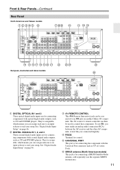
... inputs are for connecting the component with the Universal Port connector such as UP-A1 series Dock. See "Digital Audio Input Setup" on another Onkyo AV component. D V REMOTE CONTROL This V (Remote Interactive) jack can then be connected to control that component. G SIRIUS antenna (North American ...E RS232 Terminal for control. They're assignable, which means you must make an analog audio connection (RCA) between the AV receiver and the other AV component, even if they are for connecting a SIRIUS Satellite Radio antenna, sold separately (see the separate SIRIUS instructions). 11
... inputs are for connecting the component with the Universal Port connector such as UP-A1 series Dock. See "Digital Audio Input Setup" on another Onkyo AV component. D V REMOTE CONTROL This V (Remote Interactive) jack can then be connected to control that component. G SIRIUS antenna (North American ...E RS232 Terminal for control. They're assignable, which means you must make an analog audio connection (RCA) between the AV receiver and the other AV component, even if they are for connecting a SIRIUS Satellite Radio antenna, sold separately (see the separate SIRIUS instructions). 11
Owner Manual
Page 12
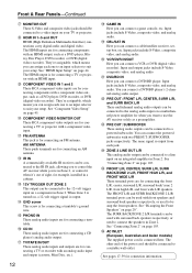
... an AM antenna. P PHONO IN These analog audio inputs are for connecting a turntable. T CBL/SAT IN Here you want to use the AV receiver solely as a preamplifier. X PRE OUT: SUBWOOFER These analog audio outputs can assign each one to an input selector to the 12-volt trigger ...). The FRONT L/R and SURR BACK/ZONE 2 L/R terminal posts can be used to control the AV receiver while you can connect a VCR or DVR (digital video recorder). M IR IN A commercially available IR receiver can be connected to the analog audio input on page 44. Q CD IN These analog audio inputs...
... an AM antenna. P PHONO IN These analog audio inputs are for connecting a turntable. T CBL/SAT IN Here you want to use the AV receiver solely as a preamplifier. X PRE OUT: SUBWOOFER These analog audio outputs can assign each one to an input selector to the 12-volt trigger ...). The FRONT L/R and SURR BACK/ZONE 2 L/R terminal posts can be used to control the AV receiver while you can connect a VCR or DVR (digital video recorder). M IR IN A commercially available IR receiver can be connected to the analog audio input on page 44. Q CD IN These analog audio inputs...

Owner Manual
Page 13
...compartment, press the small lever and remove the cover. Notes: • If the remote controller doesn't work reliably if the AV receiver is subjected to operate an Onkyo component with the polarity diagram inside the battery compartment. 3 Replace the cover and push it shut. ently, thereby draining the...batteries. • If you want to operate an Onkyo component without V connection, point the remote controller at the other component to use it. • When you intend not to use the remote controller, point it and the AV receiver's remote con- ler may not work if there's...
...compartment, press the small lever and remove the cover. Notes: • If the remote controller doesn't work reliably if the AV receiver is subjected to operate an Onkyo component with the polarity diagram inside the battery compartment. 3 Replace the cover and push it shut. ently, thereby draining the...batteries. • If you want to operate an Onkyo component without V connection, point the remote controller at the other component to use it. • When you intend not to use the remote controller, point it and the AV receiver's remote con- ler may not work if there's...
Owner Manual
Page 14
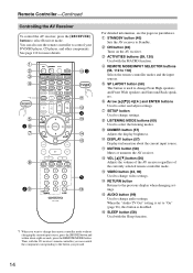
...MODE button. L MUTING button (58) Mutes or unmutes the AV receiver. B STANDBY button (40) Sets the AV receiver to select and adjust settings. Remote Controller-Continued Controlling the AV Receiver To control the AV receiver, press the [RECEIVER] button to 118) Selects the remote controller modes and the ...current input source. J DIMMER button (57) Adjusts the display brightness. M VOL [R]/[X] button (56) Adjusts the volume of the AV receiver regardless of the currently selected remote controller mode. F SP LAYOUT button (58) This button is disabled. You can control the ...
...MODE button. L MUTING button (58) Mutes or unmutes the AV receiver. B STANDBY button (40) Sets the AV receiver to select and adjust settings. Remote Controller-Continued Controlling the AV Receiver To control the AV receiver, press the [RECEIVER] button to 118) Selects the remote controller modes and the ...current input source. J DIMMER button (57) Adjusts the display brightness. M VOL [R]/[X] button (56) Adjusts the volume of the AV receiver regardless of the currently selected remote controller mode. F SP LAYOUT button (58) This button is disabled. You can control the ...

Owner Manual
Page 15
Note: An Onkyo cassette recorder connected via V can select a preset directly. Remote Controller-Continued ■ Controlling the tuner To control the AV receiver's tuner, press the [TUNER] (or [RECEIVER]) button. You can select AM or FM by pressing the [TUNER] button repeatedly. 1 Arrow [R]/[X] buttons Used to select radio stations directly in Receiver mode (see page 118...
Note: An Onkyo cassette recorder connected via V can select a preset directly. Remote Controller-Continued ■ Controlling the tuner To control the AV receiver's tuner, press the [TUNER] (or [RECEIVER]) button. You can select AM or FM by pressing the [TUNER] button repeatedly. 1 Arrow [R]/[X] buttons Used to select radio stations directly in Receiver mode (see page 118...
Owner Manual
Page 16
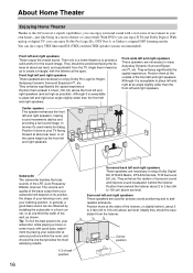
... them at one that provides the most satisfying results. 1/3 of movement in a movie theater or concert hall. Position it is to the AV receiver's superb capabilities, you can also enjoy THX Surround EX (THX-certified THX speaker system recommended). With DVDs you can be equidistant from your ...wider than the front left and right speakers. In general, a good bass sound can enjoy Dolby Pro Logic IIx, DTS Neo:6, or Onkyo's original DSP listening modes. Subwoofer The subwoofer handles the bass sounds of the bass output from the listener. Position them at the same ...
... them at one that provides the most satisfying results. 1/3 of movement in a movie theater or concert hall. Position it is to the AV receiver's superb capabilities, you can also enjoy THX Surround EX (THX-certified THX speaker system recommended). With DVDs you can be equidistant from your ...wider than the front left and right speakers. In general, a good bass sound can enjoy Dolby Pro Logic IIx, DTS Neo:6, or Onkyo's original DSP listening modes. Subwoofer The subwoofer handles the bass sounds of the bass output from the listener. Position them at the same ...

Owner Manual
Page 17
.... Powered subwoofer LINE INPUT LINE INPUT LINE INPUT LINE INPUT 17 Attaching the Speaker Labels The AV receiver's positive (+) speaker terminals are all black). Connecting a Powered Subwoofer Using a suitable cable, connect the AV receiver's PRE OUT: SUBWOOFER to set the speaker settings. Note: Front high, surround back and ...subwoofer is to match the color of each speaker cable in accordance with two PREOUT: SUBWOOFER jacks respectively. Connecting the AV receiver Connecting Your Speakers Speaker Configuration For 7.1-channel surround-sound playback, you have.
.... Powered subwoofer LINE INPUT LINE INPUT LINE INPUT LINE INPUT 17 Attaching the Speaker Labels The AV receiver's positive (+) speaker terminals are all black). Connecting a Powered Subwoofer Using a suitable cable, connect the AV receiver's PRE OUT: SUBWOOFER to set the speaker settings. Note: Front high, surround back and ...subwoofer is to match the color of each speaker cable in accordance with two PREOUT: SUBWOOFER jacks respectively. Connecting the AV receiver Connecting Your Speakers Speaker Configuration For 7.1-channel surround-sound playback, you have.

Owner Manual
Page 18
... 1 11 2 3 4 12 11 2 3 4 12 5 65 6 7 8 1. Surround right speaker 7. Do not connect them to "4ohms" (see page 47). Doing so may damage the AV receiver. • Make sure the metal core of the wire does not have an arrow printed on them to the SURR BACK/ZONE 2 L/R, FRONT WIDE L/R, or...TV/screen, while the surround back left and right and front high left and right and front wide left and right speakers. Connecting the AV receiver-Continued Using Dipole Speakers You can connect speakers with an impedance of between 4 and 16 ohms. If the impedance of any connections. &#...
... 1 11 2 3 4 12 11 2 3 4 12 5 65 6 7 8 1. Surround right speaker 7. Do not connect them to "4ohms" (see page 47). Doing so may damage the AV receiver. • Make sure the metal core of the wire does not have an arrow printed on them to the SURR BACK/ZONE 2 L/R, FRONT WIDE L/R, or...TV/screen, while the surround back left and right and front high left and right and front wide left and right speakers. Connecting the AV receiver-Continued Using Dipole Speakers You can connect speakers with an impedance of between 4 and 16 ohms. If the impedance of any connections. &#...

Owner Manual
Page 19
... left speaker Front high left speaker Center speaker Surround right speaker Surround back right speaker Surround back left speaker Surround left speaker 19 Connecting the AV receiver-Continued Connecting the Speaker Cables 1 Strip 1/2" to 5/8" (12 to 15 mm) of insulation from the ends of the speaker cables, and twist the bare wires...
... left speaker Front high left speaker Center speaker Surround right speaker Surround back right speaker Surround back left speaker Surround left speaker 19 Connecting the AV receiver-Continued Connecting the Speaker Cables 1 Strip 1/2" to 5/8" (12 to 15 mm) of insulation from the ends of the speaker cables, and twist the bare wires...

Owner Manual
Page 20
...2 L/R terminal posts connect to the front speakers' tweeter terminals. • Once you've completed the bi-amping connections shown below and turned on the AV receiver, you must set the "Speakers Type(Front)" setting to "Bi-Amp" to the right speaker's positive (+) Tweeter (high) terminal. And connect the...8226; When bi-amping is used with speakers that link the speakers' tweeter (high) and woofer (low) terminals. • Bi-amping can be used , the AV receiver is able to drive up to 5.1 speakers in the main room. • For bi-amping, the FRONT L/R terminal posts con- And connect the...
...2 L/R terminal posts connect to the front speakers' tweeter terminals. • Once you've completed the bi-amping connections shown below and turned on the AV receiver, you must set the "Speakers Type(Front)" setting to "Bi-Amp" to the right speaker's positive (+) Tweeter (high) terminal. And connect the...8226; When bi-amping is used with speakers that link the speakers' tweeter (high) and woofer (low) terminals. • Bi-amping can be used , the AV receiver is able to drive up to 5.1 speakers in the main room. • For bi-amping, the FRONT L/R terminal posts con- And connect the...

Owner Manual
Page 21
.... (European, Australian and Asian models) 2 Connect both wires of the AM antenna to achieve the best possible reception. Thumbtacks, etc. The AV receiver won't pick up any radio signals without any antenna connected, so you don't injure yourself when using it with the supplied indoor FM antenna,... try using thumbtacks. 21 Caution: Be careful that you must connect the antenna to the AM antenna push terminals, as possible from your AV receiver is for use only. 1 Assemble the AM loop antenna, inserting the tabs into the base, as shown. (North American and Taiwan models...
.... (European, Australian and Asian models) 2 Connect both wires of the AM antenna to achieve the best possible reception. Thumbtacks, etc. The AV receiver won't pick up any radio signals without any antenna connected, so you don't injure yourself when using it with the supplied indoor FM antenna,... try using thumbtacks. 21 Caution: Be careful that you must connect the antenna to the AM antenna push terminals, as possible from your AV receiver is for use only. 1 Assemble the AM loop antenna, inserting the tabs into the base, as shown. (North American and Taiwan models...

Owner Manual
Page 22
TV/FM antenna splitter To AV receiver To TV (or VCR) 22 Note that the AM loop antenna should be situated well away from possible noise sources, such as neon signs, busy ... installed outside , but good results can be grounded in accordance with the supplied indoor FM antenna, try a commercially available outdoor FM antenna instead. Connecting the AV receiver-Continued Connecting an Outdoor FM Antenna If you cannot achieve good reception with local regulations to prevent electrical shock hazards. ■ Using a TV/FM Antenna...
TV/FM antenna splitter To AV receiver To TV (or VCR) 22 Note that the AM loop antenna should be situated well away from possible noise sources, such as neon signs, busy ... installed outside , but good results can be grounded in accordance with the supplied indoor FM antenna, try a commercially available outdoor FM antenna instead. Connecting the AV receiver-Continued Connecting an Outdoor FM Antenna If you cannot achieve good reception with local regulations to prevent electrical shock hazards. ■ Using a TV/FM Antenna...
Owner Manual
Page 23
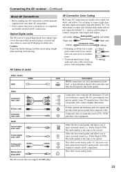
...cables away from power cords and speaker cables. This cable carries analog audio. This cable carries analog audio. 23 Connecting the AV receiver-Continued About AV Connections • Before making any AV connections, read the manuals supplied with your other video equipment. Push plugs in all the way. Jack HDMI V OPTICAL L...cable Y PB/CB PR/CR Y PB/CB PR/CR Coaxial digital audio cable Analog audio cable (RCA) Stereo mini plug cable The AV receiver does not support SCART plugs. Offers the best sound quality and allows you to connect composite video inputs and outputs. It's the most ...
...cables away from power cords and speaker cables. This cable carries analog audio. This cable carries analog audio. 23 Connecting the AV receiver-Continued About AV Connections • Before making any AV connections, read the manuals supplied with your other video equipment. Push plugs in all the way. Jack HDMI V OPTICAL L...cable Y PB/CB PR/CR Y PB/CB PR/CR Coaxial digital audio cable Analog audio cable (RCA) Stereo mini plug cable The AV receiver does not support SCART plugs. Offers the best sound quality and allows you to connect composite video inputs and outputs. It's the most ...
Owner Manual
Page 24
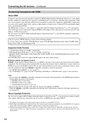
... Visual Interface): The digital display interface standard set -top boxes, and other video components. Connecting the AV receiver-Continued Connecting Components with CEC (Consumer Electronics Control), which stands for operation. The AV receiver's HDMI interface is based on Onkyo components. tion with some TVs and displays, resulting in 1999. *2 HDCP (High-bandwidth Digital Content Protection...
... Visual Interface): The digital display interface standard set -top boxes, and other video components. Connecting the AV receiver-Continued Connecting Components with CEC (Consumer Electronics Control), which stands for operation. The AV receiver's HDMI interface is based on Onkyo components. tion with some TVs and displays, resulting in 1999. *2 HDCP (High-bandwidth Digital Content Protection...


