Owner Manual
Page 1
... Troubleshooting 87 En Please read this manual thoroughly before making connections and plugging in this manual for purchasing an Onkyo AV Receiver. Following the instructions in the unit. AV Receiver TX-SR604/604E TX-SR8460 TX-SR674/674E TX-SR8467 Contents Introduction 2 Connections 18 First Time Setup 38 Basic Operations 49 Advanced Operations 66 Instruction Manual Advanced Setup...
... Troubleshooting 87 En Please read this manual thoroughly before making connections and plugging in this manual for purchasing an Onkyo AV Receiver. Following the instructions in the unit. AV Receiver TX-SR604/604E TX-SR8460 TX-SR674/674E TX-SR8467 Contents Introduction 2 Connections 18 First Time Setup 38 Basic Operations 49 Advanced Operations 66 Instruction Manual Advanced Setup...
Owner Manual
Page 4
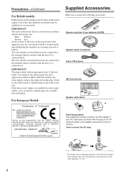
...declare in own responsibility, that indicated on the body of this adapter if your AC outlet does not match with the plug on the AV receiver's power cord (adapter varies from country to country). *How to mount the AC plug: * In catalogs and on packaging, the letter... at the end of color. 4 MIYAGI ONKYO EUROPE ELECTRONICS GmbH Front Left Front Left SP-B / Zone 2 Left SP-B / Zone 2 Left Front Right Front Right SP-B / Zone 2 Right SP-B / Zone 2 Right Surround Left Surround Left Surround Right Surround Right Center Center Surround Back Left Surround ...
...declare in own responsibility, that indicated on the body of this adapter if your AC outlet does not match with the plug on the AV receiver's power cord (adapter varies from country to country). *How to mount the AC plug: * In catalogs and on packaging, the letter... at the end of color. 4 MIYAGI ONKYO EUROPE ELECTRONICS GmbH Front Left Front Left SP-B / Zone 2 Left SP-B / Zone 2 Left Front Right Front Right SP-B / Zone 2 Right SP-B / Zone 2 Right Surround Left Surround Left Surround Right Surround Right Center Center Surround Back Left Surround ...
Owner Manual
Page 5
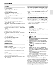
Features Amplifier • 7-channel amplifier • Optimum Gain Volume Circuitry • Zone 2 capability • 24-bit/192 kHz D/A converters • WRAT (Wide Range Amplifier Technology) • Color-coded speaker terminal posts Audio/Video • Dolby...from Dolby Laboratories. Neural Surround name and related logos are trademarks or registered trademarks of Onkyo Corporation. *6. All rights reserved. All other AV components TX-SR674/674E and TX-SR8467 Only • 95 watts per channel into 8 ohms, 20 Hz to 20 kHz, less than 0.08% total harmonic ...
Features Amplifier • 7-channel amplifier • Optimum Gain Volume Circuitry • Zone 2 capability • 24-bit/192 kHz D/A converters • WRAT (Wide Range Amplifier Technology) • Color-coded speaker terminal posts Audio/Video • Dolby...from Dolby Laboratories. Neural Surround name and related logos are trademarks or registered trademarks of Onkyo Corporation. *6. All rights reserved. All other AV components TX-SR674/674E and TX-SR8467 Only • 95 watts per channel into 8 ohms, 20 Hz to 20 kHz, less than 0.08% total harmonic ...
Owner Manual
Page 6
...25 Connecting Audio Components 33 Connecting Onkyo Components .........36 Connecting the Power Cord of Another Component 36 Turning On the AV Receiver 37 First Time Setup Automatic Speaker ... Brightness 51 Muting the AV Receiver 51 Using the Sleep Timer 51 Using Headphones 51 Using the Tuner 52 Presetting AM/FM Stations & XM Channels....53 Using RDS (European models... Zone 2 Connecting Zone 2 79 Setting the Powered Zone 2 80 Using Zone 2 81 Using the Remote Control in Zone 2 82 Controlling Other Components Entering Remote Control Codes 83 Remote Control Codes for Onkyo Components...
...25 Connecting Audio Components 33 Connecting Onkyo Components .........36 Connecting the Power Cord of Another Component 36 Turning On the AV Receiver 37 First Time Setup Automatic Speaker ... Brightness 51 Muting the AV Receiver 51 Using the Sleep Timer 51 Using Headphones 51 Using the Tuner 52 Presetting AM/FM Stations & XM Channels....53 Using RDS (European models... Zone 2 Connecting Zone 2 79 Setting the Powered Zone 2 80 Using Zone 2 81 Using the Remote Control in Zone 2 82 Controlling Other Components Entering Remote Control Codes 83 Remote Control Codes for Onkyo Components...
Owner Manual
Page 7
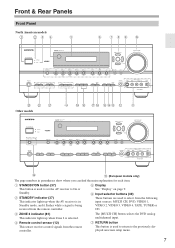
...N E (European models only) The page numbers in Standby mode, and it flashes while a signal is being received from the remote controller. B STANDBY indicator (37) This indicator lights up when Zone 2 is used to return to the previously displayed onscreen setup menu. 7 F Input selector buttons (49) These buttons ...CH, DVD, VIDEO 1, VIDEO 2, VIDEO 3, VIDEO 4, TAPE, TUNER or CD. C ZONE 2 indicator (81) This indicator lights up when the AV receiver is used to set the AV receiver to select from the remote controller. G RETURN button This button is in parentheses show where ...
...N E (European models only) The page numbers in Standby mode, and it flashes while a signal is being received from the remote controller. B STANDBY indicator (37) This indicator lights up when Zone 2 is used to return to the previously displayed onscreen setup menu. 7 F Input selector buttons (49) These buttons ...CH, DVD, VIDEO 1, VIDEO 2, VIDEO 3, VIDEO 4, TAPE, TUNER or CD. C ZONE 2 indicator (81) This indicator lights up when the AV receiver is used to set the AV receiver to select from the remote controller. G RETURN button This button is in parentheses show where ...
Owner Manual
Page 8
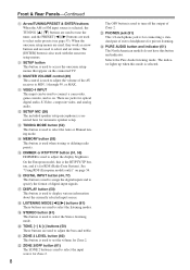
... 1 through 99, or MAX. On the European model, this mode is selected. U ZONE 2 LEVEL button (82) This button is used to turn off the output of the AV receiver to adjust the display brightness. V ZONE 2/OFF button (81) The ZONE 2 button is used to select the input source for optical digital audio, S-Video...selected input source. See "Using RDS (European models only)" on . The indicator lights up when this is the RT/PTY/TP button, and it's for Zone 2. P DIGITAL INPUT button (44, 77) This button is used to assign the digital inputs and to select the Auto or Manual tuning mode. X ...
... 1 through 99, or MAX. On the European model, this mode is selected. U ZONE 2 LEVEL button (82) This button is used to turn off the output of the AV receiver to adjust the display brightness. V ZONE 2/OFF button (81) The ZONE 2 button is used to select the input source for optical digital audio, S-Video...selected input source. See "Using RDS (European models only)" on . The indicator lights up when this is the RT/PTY/TP button, and it's for Zone 2. P DIGITAL INPUT button (44, 77) This button is used to assign the digital inputs and to select the Auto or Manual tuning mode. X ...
Owner Manual
Page 9
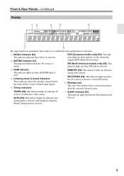
FM STEREO (52): This indicator lights up when the AV receiver is tuned to a radio station that supports RDS (Radio Data System). TUNED (52): This indicator lights up when Zone 2 is XM (North American models only) (56): This muted. Front & Rear Panels-Continued Display 12 34 5...Listening mode & format indicators These indicators show where you can find the main explanation for each item. 1 ZONE 2 indicator (81) This indicator lights up when the AV receiver is selected. 9 Tuning mode is selected, and disappears when the Manual Tuning mode is tuned into a radio ...
FM STEREO (52): This indicator lights up when the AV receiver is tuned to a radio station that supports RDS (Radio Data System). TUNED (52): This indicator lights up when Zone 2 is XM (North American models only) (56): This muted. Front & Rear Panels-Continued Display 12 34 5...Listening mode & format indicators These indicators show where you can find the main explanation for each item. 1 ZONE 2 indicator (81) This indicator lights up when the AV receiver is selected. 9 Tuning mode is selected, and disappears when the Manual Tuning mode is tuned into a radio ...
Owner Manual
Page 10
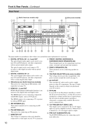
... are for connecting components with an optical digital audio output. The type of sight between the AV receiver and the remote controller is for each item. When Zone 2 is turned on a power amplifier in Zone 2. J VOLTAGE SELECTOR (only some models) 9 VOLTAGE SELECTOR 120V 220-240V N M VU T S R Q ...P ON ML K The page numbers in parentheses show where you want to use the remote controller to control the AV receiver from Zone 2, or if the AV receiver is installed in which you purchased your TV or projector. L IR IN (82) If you can be used to a video input on...
... are for connecting components with an optical digital audio output. The type of sight between the AV receiver and the remote controller is for each item. When Zone 2 is turned on a power amplifier in Zone 2. J VOLTAGE SELECTOR (only some models) 9 VOLTAGE SELECTOR 120V 220-240V N M VU T S R Q ...P ON ML K The page numbers in parentheses show where you want to use the remote controller to control the AV receiver from Zone 2, or if the AV receiver is installed in which you purchased your TV or projector. L IR IN (82) If you can be used to a video input on...
Owner Manual
Page 11
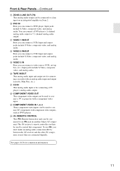
... IN This analog audio input is for connection information. 11 Front & Rear Panels-Continued O ZONE 2 LINE OUT (79) This analog audio output can be used to connect a TV or...COMPONENT VIDEO OUT This component video output can be connected to a line input on another Onkyo AV component. Input jacks include S-Video, composite video, and analog audio. W COMPONENT VIDEO... a video source (VCR, set-top box, etc.). The AV receiver's remote controller can connect a DVD player's 2-channel analog audio output or 7.1-channel analog audio output. To use , you must make an analog audio...
... IN This analog audio input is for connection information. 11 Front & Rear Panels-Continued O ZONE 2 LINE OUT (79) This analog audio output can be used to connect a TV or...COMPONENT VIDEO OUT This component video output can be connected to a line input on another Onkyo AV component. Input jacks include S-Video, composite video, and analog audio. W COMPONENT VIDEO... a video source (VCR, set-top box, etc.). The AV receiver's remote controller can connect a DVD player's 2-channel analog audio output or 7.1-channel analog audio output. To use , you must make an analog audio...
Owner Manual
Page 14
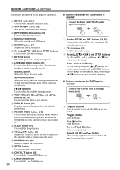
.... D MULTI CH button (50) Selects the multichannel DVD input. I Buttons used to select channels, and the [ENTER] button is selected To select the Tuner (AM/FM/XM) as the input source, press: RECEIVER 7 TAPE 4 Playback buttons On twin cassette decks, only deck B can be controlled. L... TEST TONE, CH SEL, LEVEL-, and LEVEL+ buttons (66, 70) Used to adjust the level of the currently selected remote controller mode. A ZONE 2 button (81) Used to select and adjust settings. P CINE FLTR button (66) Used with the Sleep function. Remote Controller-Continued For detailed...
.... D MULTI CH button (50) Selects the multichannel DVD input. I Buttons used to select channels, and the [ENTER] button is selected To select the Tuner (AM/FM/XM) as the input source, press: RECEIVER 7 TAPE 4 Playback buttons On twin cassette decks, only deck B can be controlled. L... TEST TONE, CH SEL, LEVEL-, and LEVEL+ buttons (66, 70) Used to adjust the level of the currently selected remote controller mode. A ZONE 2 button (81) Used to select and adjust settings. P CINE FLTR button (66) Used with the Sleep function. Remote Controller-Continued For detailed...
Owner Manual
Page 19
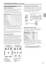
.... Front left speaker 8. Surround right speaker 7. The following table indicates the channels you should be positioned so that you need to the corresponding speaker terminal. ... Subwoofer 2. Center speaker 4. Surround back right speaker 19 Connecting the AV Receiver-Continued Connecting Your Speakers Speaker Configuration For the best surround sound ... back left (L) SURROUND BACK SPEAKERS terminals. Speaker terminal Color Front left, Zone 2 left White Front right, Zone 2 right Red Center Green Surround left Blue Surround right Gray Surround back left...
.... Front left speaker 8. Surround right speaker 7. The following table indicates the channels you should be positioned so that you need to the corresponding speaker terminal. ... Subwoofer 2. Center speaker 4. Surround back right speaker 19 Connecting the AV Receiver-Continued Connecting Your Speakers Speaker Configuration For the best surround sound ... back left (L) SURROUND BACK SPEAKERS terminals. Speaker terminal Color Front left, Zone 2 left White Front right, Zone 2 right Red Center Green Surround left Blue Surround right Gray Surround back left...
Owner Manual
Page 24
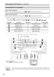
... output from your TV and listen in Zone 2. • To enjoy Dolby Digital and DTS, use connection b or c . (For recording, use its tuner to listen to the AV receiver and use a and b , or a and c .) Connection A B C a b c AV receiver COMPONENT VIDEO OUT MONITOR OUT S MONITOR OUT...a , you can listen to and record audio from your VCR or cable or satellite receiver to TV programs through the AV receiver (see page 44) TV, projector, etc. Hint! Connecting the AV Receiver-Continued Connecting Your TV or Projector Step 1: Video Connection Choose a video connection that matches ...
... output from your TV and listen in Zone 2. • To enjoy Dolby Digital and DTS, use connection b or c . (For recording, use its tuner to listen to the AV receiver and use a and b , or a and c .) Connection A B C a b c AV receiver COMPONENT VIDEO OUT MONITOR OUT S MONITOR OUT...a , you can listen to and record audio from your VCR or cable or satellite receiver to TV programs through the AV receiver (see page 44) TV, projector, etc. Hint! Connecting the AV Receiver-Continued Connecting Your TV or Projector Step 1: Video Connection Choose a video connection that matches ...

Owner Manual
Page 25
... be sure to and record audio from a DVD and listen in Zone 2. • To enjoy Dolby Digital and DTS, use connection b... audio connection that matches your TV via the same type of connection. Connection A B C a b c AV receiver COMPONENT VIDEO IN 1 DVD IN S DVD IN V DVD IN FRONT DIGITAL COAXIAL IN 1 DIGITAL OPTICAL IN 3...OPTICAL OUT Y PB PR COMPONENT VIDEO OUT L R AUDIO OUT S VIDEO OUT VIDEO OUT Connect one or the other Connection c must connect the AV receiver to your DVD player ( A , B , or C ), and then make the connection. • With connection a , you can listen to use...
... be sure to and record audio from a DVD and listen in Zone 2. • To enjoy Dolby Digital and DTS, use connection b... audio connection that matches your TV via the same type of connection. Connection A B C a b c AV receiver COMPONENT VIDEO IN 1 DVD IN S DVD IN V DVD IN FRONT DIGITAL COAXIAL IN 1 DIGITAL OPTICAL IN 3...OPTICAL OUT Y PB PR COMPONENT VIDEO OUT L R AUDIO OUT S VIDEO OUT VIDEO OUT Connect one or the other Connection c must connect the AV receiver to your DVD player ( A , B , or C ), and then make the connection. • With connection a , you can listen to use...

Owner Manual
Page 27
...L R AUDIO OUT S VIDEO OUT VCR, DVD recorder VIDEO OUT 27 Step 1: Video Connection Choose a video connection that matches your TV via the AV receiver, useful if your TV has no audio outputs. Step 2: Audio Connection Choose an audio connection that matches your VCR or DVD recorder ( A , B ... listen in Zone 2 as well, use your VCR's tuner to listen to your VCR or DVD recorder ( a , b , or c ), and then make the connection. You must be assigned (see page 46) b c A C B a COAXIAL OUT OPTICAL OUT Connect one or the other Connection b must connect the AV receiver to your ...
...L R AUDIO OUT S VIDEO OUT VCR, DVD recorder VIDEO OUT 27 Step 1: Video Connection Choose a video connection that matches your TV via the AV receiver, useful if your TV has no audio outputs. Step 2: Audio Connection Choose an audio connection that matches your VCR or DVD recorder ( A , B ... listen in Zone 2 as well, use your VCR's tuner to listen to your VCR or DVD recorder ( a , b , or c ), and then make the connection. You must be assigned (see page 46) b c A C B a COAXIAL OUT OPTICAL OUT Connect one or the other Connection b must connect the AV receiver to your ...

Owner Manual
Page 29
... the video source and listen in Zone 2. • To enjoy Dolby Digital and DTS, use connection b or c . (For recording, use your satellite or cable receiver to listen to your TV has no audio outputs. Connecting the AV Receiver-Continued Connecting a Satellite, Cable, Set...a , b , or c ), and then make the connection. With this hookup, you can use a and b , or a and c .) Connection A B C a b c AV receiver COMPONENT VIDEO IN 3 VIDEO 3 IN S VIDEO 3 IN V VIDEO 3 IN L/R DIGITAL COAXIAL IN 2 DIGITAL OPTICAL IN 2 Signal flow Video source Component video output S-Video output...
... the video source and listen in Zone 2. • To enjoy Dolby Digital and DTS, use connection b or c . (For recording, use your satellite or cable receiver to listen to your TV has no audio outputs. Connecting the AV Receiver-Continued Connecting a Satellite, Cable, Set...a , b , or c ), and then make the connection. With this hookup, you can use a and b , or a and c .) Connection A B C a b c AV receiver COMPONENT VIDEO IN 3 VIDEO 3 IN S VIDEO 3 IN V VIDEO 3 IN L/R DIGITAL COAXIAL IN 2 DIGITAL OPTICAL IN 2 Signal flow Video source Component video output S-Video output...
Owner Manual
Page 33
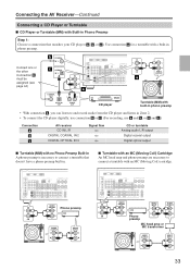
...preamp is necessary to and record audio from the CD player and listen in Zone 2. • To connect the CD player digitally, use connection b or c . (For recording, use a and b , or a and c .) Connection a b c AV receiver CD IN L/R DIGITAL COAXIAL IN 2 DIGITAL OPTICAL IN 3 Signal fl... R AUDIO INPUT L AUDIO OUTPUT L R R Phono preamp MC head amp or MC transformer AUDIO OUTPUT L R AUDIO INPUT L R 33 Connecting the AV Receiver-Continued Connecting a CD Player or Turntable I CD Player or Turntable (MM) with a built-in phono preamp. Use connection a for a turntable with Built-in...
...preamp is necessary to and record audio from the CD player and listen in Zone 2. • To connect the CD player digitally, use connection b or c . (For recording, use a and b , or a and c .) Connection a b c AV receiver CD IN L/R DIGITAL COAXIAL IN 2 DIGITAL OPTICAL IN 3 Signal fl... R AUDIO INPUT L AUDIO OUTPUT L R R Phono preamp MC head amp or MC transformer AUDIO OUTPUT L R AUDIO INPUT L R 33 Connecting the AV Receiver-Continued Connecting a CD Player or Turntable I CD Player or Turntable (MM) with a built-in phono preamp. Use connection a for a turntable with Built-in...

Owner Manual
Page 35
Connection a b c d AV receiver TAPE IN L/R TAPE OUT L/R DIGITAL COAXIAL IN 2 DIGITAL OPTICAL IN 3 DIGITAL OPTICAL OUT Signal flow Cassette, CDR, MD, or DAT recorder Analog audio L/R output ... COAXIAL OUT OPTICAL OUT OPTICAL IN L R AUDIO IN L R AUDIO OUT Cassette, CDR, MD, etc. • With connection a , you can play and record and listen in Zone 2. • To connect the recorder digitally for playback, use connections a and b , or a and c . • To connect the recorder digitally for recording, use connection d . Connecting the...
Connection a b c d AV receiver TAPE IN L/R TAPE OUT L/R DIGITAL COAXIAL IN 2 DIGITAL OPTICAL IN 3 DIGITAL OPTICAL OUT Signal flow Cassette, CDR, MD, or DAT recorder Analog audio L/R output ... COAXIAL OUT OPTICAL OUT OPTICAL IN L R AUDIO IN L R AUDIO OUT Cassette, CDR, MD, etc. • With connection a , you can play and record and listen in Zone 2. • To connect the recorder digitally for playback, use connections a and b , or a and c . • To connect the recorder digitally for recording, use connection d . Connecting the...

Owner Manual
Page 51
...multichannel input is set from 90 to cancel the sleep timer, press the [SLEEP] button repeatedly until the AV receiver sleeps, press the [SLEEP] button. Press the [RECEIVER] button, RECEIVER and then press the [MUTING] but- Notes: • Always turn off . To check the time remaining ...until the SLEEP indicator disappears. The sleep time can set . You can temporarily mute the output of headphones, the listening mode is inserted in the PHONES jack (Zone 2...
...multichannel input is set from 90 to cancel the sleep timer, press the [SLEEP] button repeatedly until the AV receiver sleeps, press the [SLEEP] button. Press the [RECEIVER] button, RECEIVER and then press the [MUTING] but- Notes: • Always turn off . To check the time remaining ...until the SLEEP indicator disappears. The sleep time can set . You can temporarily mute the output of headphones, the listening mode is inserted in the PHONES jack (Zone 2...
Owner Manual
Page 62
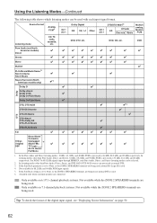
... DTS 96/24, DTS 96/24 sources are being used . 4. Available only when surround speakers are connected. : Only available on 6.1/7.1-channel playback systems. Not available while the ZONE 2 SPEAKERS terminals are being used. DVD ✔ ✔ ✔ ✔ ✔ ✔ ✔ ✔ ✔.../24 DTS-ES Discrete DTS DTS-ES Matrix DTS+Neo:6 DTS+Dolby EX DTS+PLIIx Music DTS+PLIIx Movie T-D ✔ Mono Movie Orchestra Onkyo Unplugged *6 Original Studio-Mix ✔ DSP TV Logic All Ch Stereo Full Mono 3/2.1 2/2.1 ✔ ✔ ✔ ✔ ...
... DTS 96/24, DTS 96/24 sources are being used . 4. Available only when surround speakers are connected. : Only available on 6.1/7.1-channel playback systems. Not available while the ZONE 2 SPEAKERS terminals are being used. DVD ✔ ✔ ✔ ✔ ✔ ✔ ✔ ✔ ✔.../24 DTS-ES Discrete DTS DTS-ES Matrix DTS+Neo:6 DTS+Dolby EX DTS+PLIIx Music DTS+PLIIx Movie T-D ✔ Mono Movie Orchestra Onkyo Unplugged *6 Original Studio-Mix ✔ DSP TV Logic All Ch Stereo Full Mono 3/2.1 2/2.1 ✔ ✔ ✔ ✔ ...

Owner Manual
Page 75
...Down [ ]/[ ] buttons to select "6. This is too loud compared to your AV components are explained on the AV receiver by the [SETUP] button. IntelliVolume does not affect Zone 2. SETUP 2 Use the Up and Down [ ]/[ ] buttons to select "7. IntelliVolume." Miscellaneous Setup," and then ...V1 4 V4 7 TAPE 2 V2 8 TUNER 3 V3 6 DVD 9 C D Use the INPUT SELECTOR buttons on the Miscellaneous Setup menu. 1 RECEIVER Press the [RECEIVER] button followed by using its [SETUP] button, arrow buttons, and [ENTER] button. 75 Volume Setup/OSD Setup This section explains the items on the...
...Down [ ]/[ ] buttons to select "6. This is too loud compared to your AV components are explained on the AV receiver by the [SETUP] button. IntelliVolume does not affect Zone 2. SETUP 2 Use the Up and Down [ ]/[ ] buttons to select "7. IntelliVolume." Miscellaneous Setup," and then ...V1 4 V4 7 TAPE 2 V2 8 TUNER 3 V3 6 DVD 9 C D Use the INPUT SELECTOR buttons on the Miscellaneous Setup menu. 1 RECEIVER Press the [RECEIVER] button followed by using its [SETUP] button, arrow buttons, and [ENTER] button. 75 Volume Setup/OSD Setup This section explains the items on the...


